Solution manual heat and mass transfer a practical approach 3rd edition cengel CH03 1
Bạn đang xem bản rút gọn của tài liệu. Xem và tải ngay bản đầy đủ của tài liệu tại đây (468.08 KB, 41 trang )
3-61
Critical Radius of Insulation
3-87C In a cylindrical pipe or a spherical shell, the additional insulation increases the conduction resistance
of insulation, but decreases the convection resistance of the surface because of the increase in the outer
surface area. Due to these opposite effects, a critical radius of insulation is defined as the outer radius that
provides maximum rate of heat transfer. For a cylindrical layer, it is defined as rcr = k / h where k is the
thermal conductivity of insulation and h is the external convection heat transfer coefficient.
3-88C It will decrease.
3-89C Yes, the measurements can be right. If the radius of insulation is less than critical radius of
insulation of the pipe, the rate of heat loss will increase.
3-90C No.
3-91C For a cylindrical pipe, the critical radius of insulation is defined as rcr = k / h . On windy days, the
external convection heat transfer coefficient is greater compared to calm days. Therefore critical radius of
insulation will be greater on calm days.
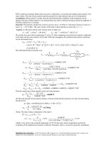
3-92 An electric wire is tightly wrapped with a 1-mm thick plastic cover. The interface temperature and the
effect of doubling the thickness of the plastic cover on the interface temperature are to be determined.
Assumptions 1 Heat transfer is steady since there is no indication of any change with time. 2 Heat transfer
is one-dimensional since there is thermal symmetry about the centerline and no variation in the axial
direction. 3 Thermal properties are constant. 4 The thermal contact resistance at the interface is negligible.
5 Heat transfer coefficient accounts for the radiation effects, if any.
Properties The thermal conductivity of plastic cover is given to be k = 0.15 W/m⋅°C.
Analysis In steady operation, the rate of heat transfer from the wire is equal to the heat generated within the
wire,
Rplastic
Rconv
Q& = W& e = VI = (8 V)(13 A) = 104 W
T1
T∞2
The total thermal resistance is
1
1
Rconv =
=
= 0.3158 °C/W
ho Ao (24 W/m 2 .°C)[π (0.0042 m)(10 m)]
ln(r2 / r1 )
ln(2.1 / 1.1)
=
= 0.0686 °C/W
2πkL
2π (0.15 W/m.°C)(10 m)
= Rconv + R plastic = 0.3158 + 0.0686 = 0.3844 °C/W
R plastic =
R total
Then the interface temperature becomes
T −T
Q& = 1 ∞ 2 ⎯
⎯→ T1 = T∞ + Q& R total = 30°C + (104 W )(0.3844 °C/W ) = 70.0°C
R total
The critical radius of plastic insulation is
k 0.15 W/m.°C
rcr = =
= 0.00625 m = 6.25 mm
h 24 W/m 2 .°C
Doubling the thickness of the plastic cover will increase the outer radius of the wire to 3 mm, which is less
than the critical radius of insulation. Therefore, doubling the thickness of plastic cover will increase the
rate of heat loss and decrease the interface temperature.
PROPRIETARY MATERIAL. © 2007 The McGraw-Hill Companies, Inc. Limited distribution permitted only to teachers and
educators for course preparation. If you are a student using this Manual, you are using it without permission.
3-62
3-93E An electrical wire is covered with 0.02-in thick plastic insulation. It is to be determined if the plastic
insulation on the wire will increase or decrease heat transfer from the wire.
Assumptions 1 Heat transfer from the wire is steady since there is no indication of any change with time. 2
Heat transfer is one-dimensional since there is thermal symmetry about the centerline and no variation in
the axial direction. 3 Thermal properties are constant. 4 The thermal contact resistance at the interface is
negligible.
Properties The thermal conductivity of plastic cover is given to be k = 0.075 Btu/h⋅ft⋅°F.
Analysis The critical radius of plastic insulation is
rcr =
k 0.075 Btu/h.ft.°F
=
= 0.03 ft = 0.36 in > r2 (= 0.0615 in)
h 2.5 Btu/h.ft 2 .°F
Wire
Insulation
Since the outer radius of the wire with insulation is smaller than critical radius
of insulation, plastic insulation will increase heat transfer from the wire.
3-94E An electrical wire is covered with 0.02-in thick plastic insulation. By considering the effect of
thermal contact resistance, it is to be determined if the plastic insulation on the wire will increase or
decrease heat transfer from the wire.
Assumptions 1 Heat transfer from the wire is steady since there is no indication of any change with time. 2
Heat transfer is one-dimensional since there is thermal symmetry about the centerline and no variation in
the axial direction. 3 Thermal properties are constant
Properties The thermal conductivity of plastic cover is given to be
k = 0.075 Btu/h⋅ft⋅°F.
Wire
Insulation
Analysis Without insulation, the total thermal
resistance is (per ft length of the wire)
Rplastic
Rinterface
Rconv
Ts
R tot = Rconv =
T∞
1
1
=
= 18.4 h.°F/Btu
2
ho Ao ( 2.5 Btu/h.ft .°F)[π (0.083/12 ft)(1 ft)]
With insulation, the total thermal resistance is
1
1
=
= 12.42 h.°F/Btu
2
ho Ao (2.5 Btu/h.ft .°F)[π (0.123/12 ft)(1 ft)]
ln(r2 / r1 )
ln(0.123 / 0.083)
=
=
= 0.835 h.°F/Btu
2πkL
2π (0.075 Btu/h.ft.°F)(1 ft )
Rconv =
Rplastic
Rinterface =
hc
0.001 h.ft 2 .°F/Btu
=
= 0.046 h.°F/Btu
Ac [π (0.083/12 ft)(1 ft)]
Rtotal = Rconv + Rplastic + Rinterface = 12.42 + 0.835 + 0.046 = 13.30 h.°F/Btu
Since the total thermal resistance decreases after insulation, plastic insulation will increase heat transfer
from the wire. The thermal contact resistance appears to have negligible effect in this case.
PROPRIETARY MATERIAL. © 2007 The McGraw-Hill Companies, Inc. Limited distribution permitted only to teachers and
educators for course preparation. If you are a student using this Manual, you are using it without permission.
3-63
3-95 A spherical ball is covered with 1-mm thick plastic insulation. It is to be determined if the plastic
insulation on the ball will increase or decrease heat transfer from it.
Assumptions 1 Heat transfer from the ball is steady since there is no indication of any change with time. 2
Heat transfer is one-dimensional since there is thermal symmetry about the midpoint. 3 Thermal properties
are constant. 4 The thermal contact resistance at the interface is negligible.
Insulation
Properties The thermal conductivity of plastic cover is given to be
k = 0.13 W/m⋅°C.
Analysis The critical radius of plastic insulation for the spherical ball is
rcr =
2k 2(0.13 W/m.°C)
=
= 0.013 m = 13 mm > r2 (= 7 mm)
h
20 W/m 2 .°C
Since the outer radius of the ball with insulation is smaller than critical radius of
insulation, plastic insulation will increase heat transfer from the wire.
PROPRIETARY MATERIAL. © 2007 The McGraw-Hill Companies, Inc. Limited distribution permitted only to teachers and
educators for course preparation. If you are a student using this Manual, you are using it without permission.
3-64
3-96 EES Prob. 3-95 is reconsidered. The rate of heat transfer from the ball as a function of the plastic
insulation thickness is to be plotted.
Analysis The problem is solved using EES, and the solution is given below.
"GIVEN"
D_1=0.005 [m]
t_ins=1 [mm]
k_ins=0.13 [W/m-C]
T_ball=50 [C]
T_infinity=15 [C]
h_o=20 [W/m^2-C]
"ANALYSIS"
D_2=D_1+2*t_ins*Convert(mm, m)
A_o=pi*D_2^2
R_conv_o=1/(h_o*A_o)
R_ins=(r_2-r_1)/(4*pi*r_1*r_2*k_ins)
r_1=D_1/2
r_2=D_2/2
R_total=R_conv_o+R_ins
Q_dot=(T_ball-T_infinity)/R_total
Q [W]
0.07248
0.1035
0.1252
0.139
0.1474
0.1523
0.1552
0.1569
0.1577
0.1581
0.1581
0.158
0.1578
0.1574
0.1571
0.1567
0.1563
0.1559
0.1556
0.1552
0 .1 6
0 .1 5
0 .1 4
0 .1 3
Q [W ]
tins [mm]
0.5
1.526
2.553
3.579
4.605
5.632
6.658
7.684
8.711
9.737
10.76
11.79
12.82
13.84
14.87
15.89
16.92
17.95
18.97
20
0 .1 2
0 .1 1
0 .1
0 .0 9
0 .0 8
0 .0 7
0
4
8
12
16
20
t in s [m m ]
PROPRIETARY MATERIAL. © 2007 The McGraw-Hill Companies, Inc. Limited distribution permitted only to teachers and
educators for course preparation. If you are a student using this Manual, you are using it without permission.
3-65
Heat Transfer from Finned Surfaces
3-97C Increasing the rate of heat transfer from a surface by increasing the heat transfer surface area.
3-98C The fin efficiency is defined as the ratio of actual heat transfer rate from the fin to the ideal heat
transfer rate from the fin if the entire fin were at base temperature, and its value is between 0 and 1. Fin
effectiveness is defined as the ratio of heat transfer rate from a finned surface to the heat transfer rate from
the same surface if there were no fins, and its value is expected to be greater than 1.
3-99C Heat transfer rate will decrease since a fin effectiveness smaller than 1 indicates that the fin acts as
insulation.
3-100C Fins enhance heat transfer from a surface by increasing heat transfer surface area for convection
heat transfer. However, adding too many fins on a surface can suffocate the fluid and retard convection,
and thus it may cause the overall heat transfer coefficient and heat transfer to decrease.
3-101C Effectiveness of a single fin is the ratio of the heat transfer rate from the entire exposed surface of
the fin to the heat transfer rate from the fin base area. The overall effectiveness of a finned surface is
defined as the ratio of the total heat transfer from the finned surface to the heat transfer from the same
surface if there were no fins.
3-102C Fins should be attached on the air side since the convection heat transfer coefficient is lower on the
air side than it is on the water side.
3-103C Fins should be attached to the outside since the heat transfer coefficient inside the tube will be
higher due to forced convection. Fins should be added to both sides of the tubes when the convection
coefficients at the inner and outer surfaces are comparable in magnitude.
3-104C Welding or tight fitting introduces thermal contact resistance at the interface, and thus retards heat
transfer. Therefore, the fins formed by casting or extrusion will provide greater enhancement in heat
transfer.
3-105C If the fin is too long, the temperature of the fin tip will approach the surrounding temperature and
we can neglect heat transfer from the fin tip. Also, if the surface area of the fin tip is very small compared
to the total surface area of the fin, heat transfer from the tip can again be neglected.
3-106C Increasing the length of a fin decreases its efficiency but increases its effectiveness.
3-107C Increasing the diameter of a fin increases its efficiency but decreases its effectiveness.
3-108C The thicker fin has higher efficiency; the thinner one has higher effectiveness.
3-109C The fin with the lower heat transfer coefficient has the higher efficiency and the higher
effectiveness.
PROPRIETARY MATERIAL. © 2007 The McGraw-Hill Companies, Inc. Limited distribution permitted only to teachers and
educators for course preparation. If you are a student using this Manual, you are using it without permission.
3-66
3-110 A relation is to be obtained for the fin efficiency for a fin of constant cross-sectional area Ac ,
perimeter p, length L, and thermal conductivity k exposed to convection to a medium at T∞ with a heat
transfer coefficient h. The relation is to be simplified for circular fin of diameter D and for a rectangular fin
of thickness t.
Assumptions 1 The fins are sufficiently long so that the temperature of the fin at the tip is nearly T∞ . 2
Heat transfer from the fin tips is negligible.
Analysis Taking the temperature of the fin at the base to be Tb and using the heat transfer relation for a
long fin, fin efficiency for long fins can be expressed as
η fin =
Actual heat transfer rate from the fin
Ideal heat transfer rate from the fin
if the entire fin were at base temperature
=
hpkAc (Tb − T∞ )
hA fin (Tb − T∞ )
=
hpkAc
hpL
1
=
L
h, T∞
D
Tb
kAc
ph
p= πD
Ac = πD2/4
This relation can be simplified for a circular fin of diameter D
and rectangular fin of thickness t and width w to be
η fin,circular =
1
L
kAc
1
=
ph
L
k (πD 2 / 4)
1
=
(πD)h
2L
η fin,rectangular =
1
L
kAc
1
=
ph
L
k ( wt )
1
≅
2( w + t )h L
kD
h
k ( wt ) 1
=
2 wh
L
kt
2h
3-111 The maximum power rating of a transistor whose case temperature is not to exceed 80 ° C is to be
determined.
Assumptions 1 Steady operating conditions exist. 2 The transistor case is isothermal at 80 ° C .
Properties The case-to-ambient thermal resistance is
given to be 20 ° C / W .
Analysis The maximum power at which this transistor
can be operated safely is
Q& =
ΔT
R case − ambient
=
R
Ts
T∞
Tcase − T∞
(80 − 40) °C
=
= 1.6 W
Rcase − ambient
25 °C/W
PROPRIETARY MATERIAL. © 2007 The McGraw-Hill Companies, Inc. Limited distribution permitted only to teachers and
educators for course preparation. If you are a student using this Manual, you are using it without permission.
3-67
3-112 A fin is attached to a surface. The percent error in the rate of heat transfer from the fin when the
infinitely long fin assumption is used instead of the adiabatic fin tip assumption is to be determined.
Assumptions 1 Steady operating conditions exist. 2 The temperature along the fins varies in one direction
only (normal to the plate). 3 The heat transfer coefficient is constant and uniform over the entire fin
surface. 4 The thermal properties of the fins are constant. 5 The heat transfer coefficient accounts for the
effect of radiation from the fins.
Properties The thermal conductivity of the aluminum fin is given to be k = 237 W/m⋅°C.
Analysis The expressions for the heat transfer from a fin under
infinitely long fin and adiabatic fin tip assumptions are
Q& long fin = hpkAc (Tb − T∞ )
D = 4 mm
Q& ins. tip = hpkAc (Tb − T∞ ) tanh(mL)
L = 10 cm
The percent error in using long fin assumption can be expressed as
% Error =
Q& long fin − Q& ins. tip
=
Q&
hpkAc (Tb − T∞ ) − hpkAc (Tb − T∞ ) tanh( mL)
hpkAc (Tb − T∞ ) tanh( mL)
ins. tip
where
m=
hp
=
kAc
(12 W/m 2 .°C)π (0.004 m)
(237 W/m.°C)π (0.004 m) / 4
2
=
1
−1
tanh( mL)
= 7.116 m -1
Substituting,
% Error =
1
1
−1 =
− 1 = 0.635 = 63.5%
tanh( mL)
tanh (7.116 m -1 )(0.10 m)
[
]
This result shows that using infinitely long fin assumption may yield results grossly in error.
3-113 A very long fin is attached to a flat surface. The fin temperature at a certain distance from the base
and the rate of heat loss from the entire fin are to be determined.
Assumptions 1 Steady operating conditions exist. 2 The temperature along the fins varies in one direction
only (normal to the plate). 3 The heat transfer coefficient is constant and uniform over the entire fin
surface. 4 The thermal properties of the fins are constant. 5 The heat transfer coefficient accounts for the
effect of radiation from the fins.
Properties The thermal conductivity of the fin is given to be k = 200 W/m⋅°C.
Analysis The fin temperature at a distance of 5 cm from the base is determined from
m=
hp
=
kAc
(20 W/m 2 .°C)(2 × 0.05 + 2 × 0.001)m
(200 W/m.°C)(0.05 × 0.001)m
2
= 14.3 m -1
T − T∞
T − 20
= e − mx ⎯
⎯→
= e − (14.3)(0.05) ⎯
⎯→ T = 29.8°C
40 − 20
Tb − T∞
The rate of heat loss from this very long fin is
40°C
20°C
Q& long fin = hpkAc (Tb − T∞ )
= (20)(2 × 0.05 + 2 × 0.001)(200(0.05 × 0.001) (40 − 20)
= 2.9 W
PROPRIETARY MATERIAL. © 2007 The McGraw-Hill Companies, Inc. Limited distribution permitted only to teachers and
educators for course preparation. If you are a student using this Manual, you are using it without permission.
3-68
3-114 Circular fins made of copper are considered. The function θ(x) = T(x) - T∞ along a fin is to be
expressed and the temperature at the middle is to be determined. Also, the rate of heat transfer from each
fin, the fin effectiveness, and the total rate of heat transfer from the wall are to be determined.
Assumptions 1 Steady operating conditions exist. 2 The temperature along the fins varies in one direction
only (normal to the plate). 3 The heat transfer coefficient is constant and uniform over the entire finned and
unfinned wall surfaces. 4 The thermal properties of the fins are constant. 5 The heat transfer coefficient
accounts for the effect of radiation from the fins.
Properties The thermal conductivity of the copper fin is
given to be k = 400 W/m⋅°C.
T∞ , h
Analysis (a) For fin with prescribed tip temperature,
θ θ L / θ b sinh( mx) + sinh[ m( L − x)]
=
θb
sinh( mL)
Ts1
With θb = Tb-T∞ = Ts1 and θL = TL-T∞ = 0, the equation becomes
Ts2
θ sinh[ m( L − x)] exp[m( L − x)] − exp[− m( L − x)]
=
=
θb
sinh( mL)
exp(mL) − exp(− mL)
L
D
For x = L/2:
m=
x
hp
=
kAc
(100)π (0.001)
(400)π (0.001) 2 /4
= 31.6 m -1
sinh(mL / 2)
exp(mL / 2) − exp(−mL / 2)
= Ts1
sinh(mL)
exp(mL) − exp(−mL)
exp(31.6 × 0.0254 / 2) − exp(−31.6 × 0.0254 / 2)
= (132)
= 61.6°C
exp(31.6 × 0.0254) − exp(−31.6 × 0.0254)
θ L / 2 = TL / 2 = θ b
(b) The rate of heat transfer from a single fin is
q& one fin = θ b hpkAc
cosh(mL)
sinh(mL)
= (132 − 0) (100)π (0.001)(400)π (0.001) 2 / 4
cosh(31.6 × 0.0254)
sinh(31.6 × 0.0254)
= 1.97 W
The effectiveness of the fin is
ε=
qf
Ac hθ b
=
1.97
0.25π (0.001) 2 (100)(132 − 0)
= 190
Since ε >> 2, the fins are well justified.
(c) The total rate of heat transfer is
q& total = q& fins + q& base
= n fin q one fin + ( Awall − n fin Ac )hθ b
= (625)(1.97) + [0.1× 0.1 − 625 × 0.25π (0.001) 2 ](100)(132)
= 1363 W
PROPRIETARY MATERIAL. © 2007 The McGraw-Hill Companies, Inc. Limited distribution permitted only to teachers and
educators for course preparation. If you are a student using this Manual, you are using it without permission.
3-69
3-115 A commercially available heat sink is to be selected to keep the case temperature of a transistor
below 90°C in an environment at 20°C.
Assumptions 1 Steady operating conditions exist. 2 The
transistor case is isothermal at 90°C. 3 The contact
resistance between the transistor and the heat sink is
negligible.
Ts
R
T∞
Analysis The thermal resistance between the transistor
attached to the sink and the ambient air is determined to be
Q& =
ΔT
Rcase − ambient
⎯
⎯→ Rcase −ambient =
Ttransistor − T∞ (90 − 20)°C
=
= 1.75 °C/W
40 W
Q&
The thermal resistance of the heat sink must be below 1.75°C/W. Table 3-6 reveals that HS6071 in vertical
position, HS5030 and HS6115 in both horizontal and vertical position can be selected.
3-116 A commercially available heat sink is to be selected to keep the case temperature of a transistor
below 55°C in an environment at 18°C.
Assumptions 1 Steady operating conditions exist. 2 The transistor
case is isothermal at 55 ° C . 3 The contact resistance between the
transistor and the heat sink is negligible.
Ts
R
T∞
Analysis The thermal resistance between the transistor attached to
the sink and the ambient air is determined to be
Q& =
− T∞ (55 − 18)°C
T
ΔT
⎯
⎯→ R case − ambient = transistor
=
= 1.5 °C/W
&
25 W
Rcase − ambient
Q
The thermal resistance of the heat sink must be below 1.5°C/W. Table 3-6 reveals that HS5030 in both
horizontal and vertical positions, HS6071 in vertical position, and HS6115 in both horizontal and vertical
positions can be selected.
PROPRIETARY MATERIAL. © 2007 The McGraw-Hill Companies, Inc. Limited distribution permitted only to teachers and
educators for course preparation. If you are a student using this Manual, you are using it without permission.
3-70
3-117 Circular aluminum fins are to be attached to the tubes of a heating system. The increase in heat
transfer from the tubes per unit length as a result of adding fins is to be determined.
Assumptions 1 Steady operating conditions exist. 2 The heat transfer coefficient is constant and uniform
over the entire fin surfaces. 3 Thermal conductivity is constant. 4 Heat transfer by radiation is negligible.
Properties The thermal conductivity of the fins is given to be k = 186 W/m⋅°C.
Analysis In case of no fins, heat transfer from the tube per meter of its length is
Ano fin = πD1 L = π (0.05 m)(1 m) = 0.1571 m 2
Q& no fin = hAno fin (Tb − T∞ ) = (40 W/m 2 .°C)(0.1571 m 2 )(180 − 25)°C = 974 W
180°C
The efficiency of these circular fins is, from the efficiency curve, Fig. 3-43
L = ( D 2 − D1 ) / 2 = (0.06 − 0.05) / 2 = 0.005 m
r2 + (t / 2) 0.03 + (0.001 / 2)
=
0.025
r1
⎛ h ⎞
⎟
⎟
⎝ kA p ⎠
L3c / 2 ⎜
⎜
1/ 2
t⎞ h
⎛
= ⎜L+ ⎟
2
⎝
⎠ kt
0.001 ⎞
⎛
= ⎜ 0.005 +
⎟
2 ⎠
⎝
⎫
⎪
⎪
= 1.22
⎪
⎪
⎪
⎬η fin = 0.97
⎪
⎪
⎪
2o
40 W/m C
⎪
0
.
08
=
⎪
(186 W/m o C)(0.001 m)
⎭
25°C
Heat transfer from a single fin is
Afin = 2π (r2 2 − r1 2 ) + 2πr2 t = 2π (0.03 2 − 0.025 2 ) + 2π (0.03)(0.001) = 0.001916 m 2
Q& fin = η fin Q& fin,max = η fin hAfin (Tb − T∞ )
= 0.97(40 W/m 2 .°C)(0.001916 m 2 )(180 − 25)°C
= 11.53 W
Heat transfer from a single unfinned portion of the tube is
Aunfin = πD1 s = π (0.05 m)(0.003 m) = 0.0004712 m 2
Q& unfin = hAunfin (Tb − T∞ ) = (40 W/m 2 .°C)(0.0004712 m 2 )(180 − 25)°C = 2.92 W
There are 250 fins and thus 250 interfin spacings per meter length of the tube. The total heat transfer from
the finned tube is then determined from
Q& total,fin = n(Q& fin + Q& unfin ) = 250(11.53 + 2.92) = 3613 W
Therefore the increase in heat transfer from the tube per meter of its length as a result of the addition of the
fins is
Q& increase = Q& total,fin − Q& no fin = 3613 − 974 = 2639 W
PROPRIETARY MATERIAL. © 2007 The McGraw-Hill Companies, Inc. Limited distribution permitted only to teachers and
educators for course preparation. If you are a student using this Manual, you are using it without permission.
3-71
3-118E The handle of a stainless steel spoon partially immersed in boiling water extends 7 in. in the air
from the free surface of the water. The temperature difference across the exposed surface of the spoon
handle is to be determined.
Assumptions 1 The temperature of the submerged portion of the spoon is equal to the water temperature. 2
The temperature in the spoon varies in the axial direction only (along the spoon), T(x). 3 The heat transfer
from the tip of the spoon is negligible. 4 The heat transfer coefficient is constant and uniform over the
entire spoon surface. 5 The thermal properties of the spoon are constant. 6 The heat transfer coefficient
accounts for the effect of radiation from the spoon.
Properties The thermal conductivity of the spoon is given to be k = 8.7 Btu/h⋅ft⋅°F.
Analysis Noting that the cross-sectional area of the spoon is constant and measuring x from the free surface
of water, the variation of temperature along the spoon can be expressed as
T ( x) − T∞ cosh m( L − x)
=
Tb − T∞
cosh mL
h, T∞
where
p = 2(0.5 / 12 ft + 0.08 / 12 ft ) = 0.0967 ft
Ac = (0.5 / 12 ft)(0.08 / 12 ft ) = 0.000278 ft
m=
0.08 in
Tb
hp
=
kAc
L = 7 in
2
(3 Btu/h.ft 2 .°F)(0.0967 ft )
(8.7 Btu/h.ft.°F)(0.000278 ft )
2
0.5 in
= 10.95 ft -1
Noting that x = L = 7/12=0.583 ft at the tip and substituting, the tip temperature
of the spoon is determined to be
cosh m( L − L)
cosh mL
cosh 0
1
= 75°F + (200 − 75)
= 75°F + (200 − 75)
= 75.4°F
cosh(10.95 × 0.583)
296
T ( L) = T∞ + (Tb − T∞ )
Therefore, the temperature difference across the exposed section of the spoon handle is
ΔT = Tb − Ttip = (200 − 75.4)°F = 124.6°F
PROPRIETARY MATERIAL. © 2007 The McGraw-Hill Companies, Inc. Limited distribution permitted only to teachers and
educators for course preparation. If you are a student using this Manual, you are using it without permission.
3-72
3-119E The handle of a silver spoon partially immersed in boiling water extends 7 in. in the air from the
free surface of the water. The temperature difference across the exposed surface of the spoon handle is to
be determined.
Assumptions 1 The temperature of the submerged portion of the spoon is equal to the water temperature. 2
The temperature in the spoon varies in the axial direction only (along the spoon), T(x). 3 The heat transfer
from the tip of the spoon is negligible. 4 The heat transfer coefficient is constant and uniform over the
entire spoon surface. 5 The thermal properties of the spoon are constant. 6 The heat transfer coefficient
accounts for the effect of radiation from the spoon..
Properties The thermal conductivity of the spoon is given to be k = 247 Btu/h⋅ft⋅°F.
Analysis Noting that the cross-sectional area of the spoon is constant and measuring x from the free surface
of water, the variation of temperature along the spoon can be expressed as
T ( x) − T∞ cosh m( L − x)
=
Tb − T∞
cosh mL
h, T∞
where
p = 2(0.5 / 12 ft + 0.08 / 12 ft ) = 0.0967 ft
Ac = (0.5 / 12 ft)(0.08 / 12 ft ) = 0.000278 ft
m=
0.08 in
Tb
hp
=
kAc
L = 7 in
2
(3 Btu/h.ft 2 .°F)(0.0967 ft )
(247 Btu/h.ft.°F)(0.000278 ft )
2
0.5 in
= 2.055 ft -1
Noting that x = L = 0.7/12=0.583 ft at the tip and substituting, the tip
temperature of the spoon is determined to be
cosh m( L − L)
cosh mL
cosh 0
1
= 75°F + (200 − 75)
= 75°F + (200 − 75)
= 144.1°F
cosh(2.055 × 0.583)
1.81
T ( L) = T∞ + (Tb − T∞ )
Therefore, the temperature difference across the exposed section of the spoon handle is
ΔT = Tb − Ttip = (200 − 144.1)°C = 55.9°F
PROPRIETARY MATERIAL. © 2007 The McGraw-Hill Companies, Inc. Limited distribution permitted only to teachers and
educators for course preparation. If you are a student using this Manual, you are using it without permission.
3-73
3-120E EES Prob. 3-118E is reconsidered. The effects of the thermal conductivity of the spoon material
and the length of its extension in the air on the temperature difference across the exposed surface of the
spoon handle are to be investigated.
Analysis The problem is solved using EES, and the solution is given below.
"GIVEN"
k_spoon=8.7 [Btu/h-ft-F]
T_w=200 [F]
T_infinity=75 [F]
A_c=0.08/12*0.5/12 [ft^2]
L=7 [in]
h=3 [Btu/h-ft^2-F]
"ANALYSIS"
p=2*(0.08/12+0.5/12)
a=sqrt((h*p)/(k_spoon*A_c))
(T_tip-T_infinity)/(T_w-T_infinity)=cosh(a*(L-x)*Convert(in, ft))/cosh(a*L*Convert(in, ft))
x=L "for tip temperature"
DELTAT=T_w-T_tip
kspoon [Btu/h.ft.F]
5
16.58
28.16
39.74
51.32
62.89
74.47
86.05
97.63
109.2
120.8
132.4
143.9
155.5
167.1
178.7
190.3
201.8
213.4
225
ΔT [F]
124.9
122.6
117.8
112.5
107.1
102
97.21
92.78
88.69
84.91
81.42
78.19
75.19
72.41
69.82
67.4
65.14
63.02
61.04
59.17
PROPRIETARY MATERIAL. © 2007 The McGraw-Hill Companies, Inc. Limited distribution permitted only to teachers and
educators for course preparation. If you are a student using this Manual, you are using it without permission.
3-74
ΔT [F]
122.4
123.4
124
124.3
124.6
124.7
124.8
124.9
124.9
125
125
125
125
125
125
kspoon [Btu/h.ft.F]
5
5.5
6
6.5
7
7.5
8
8.5
9
9.5
10
10.5
11
11.5
12
130
120
110
100
Δ T [F]
90
80
70
60
50
0
45
90
135
180
225
k spoon [Btu/h-ft-F]
125.5
125
124.5
Δ T [F]
124
123.5
123
122.5
122
5
6
7
8
9
10
11
12
L [in]
PROPRIETARY MATERIAL. © 2007 The McGraw-Hill Companies, Inc. Limited distribution permitted only to teachers and
educators for course preparation. If you are a student using this Manual, you are using it without permission.
3-75
3-121 A circuit board houses 80 logic chips on one side, dissipating 0.04 W each through the back side of
the board to the surrounding medium. The temperatures on the two sides of the circuit board are to be
determined for the cases of no fins and 864 aluminum pin fins on the back surface.
Assumptions 1 Steady operating conditions exist. 2 The temperature in the board and along the fins varies
in one direction only (normal to the board). 3 All the heat generated in the chips is conducted across the
circuit board, and is dissipated from the back side of the board. 4 Heat transfer from the fin tips is
negligible. 5 The heat transfer coefficient is constant and uniform over the entire fin surface. 6 The
thermal properties of the fins are constant. 7 The heat transfer coefficient accounts for the effect of
radiation from the fins.
Properties The thermal conductivities are given to be k = 30 W/m⋅°C for the circuit board, k = 237 W/m⋅°C
for the aluminum plate and fins, and k = 1.8 W/m⋅°C for the epoxy adhesive.
Analysis (a) The total rate of heat transfer dissipated by the chips is
Q& = 80 × (0.04 W) = 3.2 W
2 cm
The individual resistances are
Repoxy
Rboard
RAluminum
Rconv
T∞2
T1
T2
A = (0.12 m)(0.18 m) = 0.0216 m 2
L
0.003 m
=
= 0.00463 °C/W
kA (30 W/m.°C)(0.0216 m 2 )
1
1
=
=
= 1.1574 °C/W
hA (40 W/m 2 .°C)(0.0216 m 2 )
R board =
R conv
R total = R board + Rconv = 0.00463 + 1.1574 = 1.1620 °C/W
The temperatures on the two sides of the circuit board are
T −T
Q& = 1 ∞ 2 ⎯
⎯→ T1 = T∞ 2 + Q& R total = 40°C + (3.2 W )(1.1620 °C/W) = 43.7°C
R total
T −T
Q& = 1 2 ⎯
⎯→ T2 = T1 − Q& R board = 43.7°C − (3.2 W )(0.00463 °C/W) = 43.7 − 0.015 ≅ 43.7°C
R board
Therefore, the board is nearly isothermal.
(b) Noting that the cross-sectional areas of the fins are constant, the efficiency of the circular fins can be
determined to be
hπD
4(40 W/m 2 .°C)
= 16.43 m -1
(237 W/m.°C)(0.0025 m)
m=
hp
=
kAc
η fin =
tanh mL tanh(16.43 m -1 × 0.02 m)
=
= 0.965
mL
16.43 m -1 × 0.02 m
kπD 2 / 4
=
4h
=
kD
The fins can be assumed to be at base temperature provided that the fin area is modified by multiplying it
by 0.965. Then the various thermal resistances are
Repoxy =
0.0002 m
L
=
= 0.0051 °C/W
kA (1.8 W/m.°C)(0.0216 m 2 )
PROPRIETARY MATERIAL. © 2007 The McGraw-Hill Companies, Inc. Limited distribution permitted only to teachers and
educators for course preparation. If you are a student using this Manual, you are using it without permission.
3-76
R Al =
0.002 m
L
=
= 0.00039 °C/W
kA (237 W/m.°C)(0.0216 m 2 )
Afinned = η fin nπDL = 0.965 × 864π (0.0025 m)(0.02 m) = 0.131 m 2
Aunfinned = 0.0216 − 864
πD 2
4
Atotal,with fins = Afinned + Aunfinned
R conv =
= 0.0216 − 864 ×
π (0.0025) 2
4
= 0.131 + 0.0174 = 0.148 m 2
= 0.0174 m 2
1
1
=
= 0.1689 °C/W
hAtotal, with fins (40 W/m 2 .°C)(0.148 m 2 )
R total = R board + Repoxy + Raluminum + Rconv
= 0.00463 + 0.0051 + 0.00039 + 0.1689 = 0.1790 °C/W
Then the temperatures on the two sides of the circuit board becomes
T −T
Q& = 1 ∞ 2 ⎯
⎯→ T1 = T∞ 2 + Q& R total = 40°C + (3.2 W )(0.1790 °C/W) = 40.6°C
R total
T −T
Q& = 1 2 ⎯
⎯→ T2 = T1 − Q& R board = 40.6°C − (3.2 W )(0.00463 °C/W) = 40.6 − 0.015 ≅ 40.6°C
R board
PROPRIETARY MATERIAL. © 2007 The McGraw-Hill Companies, Inc. Limited distribution permitted only to teachers and
educators for course preparation. If you are a student using this Manual, you are using it without permission.
3-77
3-122 A circuit board houses 80 logic chips on one side, dissipating 0.04 W each through the back side of
the board to the surrounding medium. The temperatures on the two sides of the circuit board are to be
determined for the cases of no fins and 864 copper pin fins on the back surface.
Assumptions 1 Steady operating conditions exist. 2 The temperature in the board and along the fins varies
in one direction only (normal to the board). 3 All the heat generated in the chips is conducted across the
circuit board, and is dissipated from the back side of the board. 4 Heat transfer from the fin tips is
negligible. 5 The heat transfer coefficient is constant and uniform over the entire fin surface. 6 The
thermal properties of the fins are constant. 7 The heat transfer coefficient accounts for the effect of
radiation from the fins.
Properties The thermal conductivities are given to be k = 20 W/m⋅°C for the circuit board, k = 386 W/m⋅°C
for the copper plate and fins, and k = 1.8 W/m⋅°C for the epoxy adhesive.
Analysis (a) The total rate of heat transfer dissipated by the chips is
2 cm
Q& = 80 × (0.04 W) = 3.2 W
The individual resistances are
Rboard
Repoxy
RAluminum
Rconv
T∞2
T1
T2
A = (0.12 m)(0.18 m) = 0.0216 m 2
0.003 m
L
=
= 0.00463 °C/W
kA (30 W/m.°C)(0.0216 m 2 )
1
1
=
=
= 1.1574 °C/W
hA (40 W/m 2 .°C)(0.0216 m 2 )
R board =
Rconv
R total = R board + Rconv = 0.00463 + 1.1574 = 1.1620 °C/W
The temperatures on the two sides of the circuit board are
T −T
Q& = 1 ∞ 2 ⎯
⎯→ T1 = T∞ 2 + Q& R total = 40°C + (3.2 W )(1.1620 °C/W) = 43.7°C
R total
T − T2
Q& = 1
⎯
⎯→ T2 = T1 − Q& R board = 43.7°C − (3.2 W )(0.00463 °C/W) = 43.7 − 0.015 ≅ 43.7°C
R board
Therefore, the board is nearly isothermal.
(b) Noting that the cross-sectional areas of the fins are constant, the efficiency of the circular fins can be
determined to be
hπD
4(40 W/m 2 .°C)
4h
= 12.88 m -1
=
(386 W/m.°C)(0.0025 m)
kD
m=
hp
=
kAc
η fin =
tanh mL tanh(12.88 m -1 × 0.02 m)
=
= 0.978
mL
12.88 m -1 × 0.02 m
kπD 2 / 4
=
The fins can be assumed to be at base temperature provided that the fin area is modified by multiplying it
by 0.978. Then the various thermal resistances are
Repoxy =
R Cu =
0.0002 m
L
=
= 0.0051 °C/W
kA (1.8 W/m.°C)(0.0216 m 2 )
L
0.002 m
=
= 0.00024 °C/W
kA (386 W/m.°C)(0.0216 m 2 )
PROPRIETARY MATERIAL. © 2007 The McGraw-Hill Companies, Inc. Limited distribution permitted only to teachers and
educators for course preparation. If you are a student using this Manual, you are using it without permission.
3-78
Afinned = η fin nπDL = 0.978 × 864π (0.0025 m)(0.02 m) = 0.133 m 2
Aunfinned = 0.0216 − 864
πD 2
= 0.0216 − 864 ×
π (0.0025) 2
4
4
Atotal,with fins = Afinned + Aunfinned = 0.133 + 0.0174 = 0.150 m 2
R conv =
1
hAtotal, with fins
=
1
(40 W/m .°C)(0.150 m 2 )
2
= 0.0174 m 2
= 0.1667 °C/W
R total = R board + Repoxy + Raluminum + Rconv
= 0.00463 + 0.0051 + 0.00024 + 0.1667 = 0.1767 °C/W
Then the temperatures on the two sides of the circuit board becomes
T −T
Q& = 1 ∞ 2 ⎯
⎯→ T1 = T∞ 2 + Q& R total = 40°C + (3.2 W )(0.1767 °C/W) = 40.6°C
R total
T −T
Q& = 1 2 ⎯
⎯→ T2 = T1 − Q& R board = 40.6°C − (3.2 W )(0.00463 °C/W) = 40.6 − 0.015 ≅ 40.6°C
R board
PROPRIETARY MATERIAL. © 2007 The McGraw-Hill Companies, Inc. Limited distribution permitted only to teachers and
educators for course preparation. If you are a student using this Manual, you are using it without permission.
3-79
3-123 A hot plate is to be cooled by attaching aluminum pin fins on one side. The rate of heat transfer from
the 1 m by 1 m section of the plate and the effectiveness of the fins are to be determined.
Assumptions 1 Steady operating conditions exist. 2 The temperature along the fins varies in one direction
only (normal to the plate). 3 Heat transfer from the fin tips is negligible. 4 The heat transfer coefficient is
constant and uniform over the entire fin surface. 5 The thermal properties of the fins are constant. 6 The
heat transfer coefficient accounts for the effect of radiation from the fins.
Properties The thermal conductivity of the aluminum plate and fins is given to be k = 237 W/m⋅°C.
Analysis Noting that the cross-sectional areas of the fins are
constant, the efficiency of the circular fins can be determined to be
hπD
4(35 W/m 2 .°C)
= 15.37 m -1
(237 W/m.°C)(0.0025 m)
m=
hp
=
kAc
η fin =
tanh mL tanh(15.37 m -1 × 0.03 m)
=
= 0.935
mL
15.37 m -1 × 0.03 m
kπD 2 / 4
4h
=
kD
=
3 cm
D=0.25 cm
0.6 cm
The number of fins, finned and unfinned surface areas,
and heat transfer rates from those areas are
n=
1m2
= 27,777
(0.006 m)(0.006 m)
⎡
⎡
π (0.0025) 2 ⎤
πD 2 ⎤
Afin = 27777 ⎢πDL +
⎥
⎥ = 27777 ⎢π (0.0025)(0.03) +
4 ⎦⎥
4
⎣⎢
⎣⎢
⎦⎥
= 6.68 m 2
2⎤
⎡
⎛ πD 2 ⎞
⎟ = 1 − 27777 ⎢ π (0.0025) ⎥ = 0.86 m 2
Aunfinned = 1 − 27777⎜⎜
⎟
4
⎝ 4 ⎠
⎣⎢
⎦⎥
&
&
=η Q
= η hA (T − T )
Q
finned
fin
fin, max
fin
fin
∞
b
= 0.935(35 W/m .°C)(6.68 m )(100 − 30)°C
= 15,300 W
2
2
Q& unfinned = hAunfinned (Tb − T∞ ) = (35 W/m 2 .°C)(0.86 m 2 )(100 − 30)°C
= 2107 W
Then the total heat transfer from the finned plate becomes
Q& total,fin = Q& finned + Q& unfinned = 15,300 + 2107 = 1.74 × 10 4 W = 17.4 kW
The rate of heat transfer if there were no fin attached to the plate would be
Ano fin = (1 m)(1 m) = 1 m 2
Q& no fin = hAno fin (Tb − T∞ ) = (35 W/m 2 .°C)(1 m 2 )(100 − 30)°C = 2450 W
Then the fin effectiveness becomes
ε fin =
Q& fin
17,400
=
= 7.10
&
2450
Q no fin
PROPRIETARY MATERIAL. © 2007 The McGraw-Hill Companies, Inc. Limited distribution permitted only to teachers and
educators for course preparation. If you are a student using this Manual, you are using it without permission.
3-80
3-124 A hot plate is to be cooled by attaching copper pin fins on one side. The rate of heat transfer from
the 1 m by 1 m section of the plate and the effectiveness of the fins are to be determined.
Assumptions 1 Steady operating conditions exist. 2 The temperature along the fins varies in one direction
only (normal to the plate). 3 Heat transfer from the fin tips is negligible. 4 The heat transfer coefficient is
constant and uniform over the entire fin surface. 5 The thermal properties of the fins are constant. 6 The
heat transfer coefficient accounts for the effect of radiation from the fins.
Properties The thermal conductivity of the copper plate and fins is
given to be k = 386 W/m⋅°C.
3 cm
Analysis Noting that the cross-sectional areas of the fins are
constant, the efficiency of the circular fins can be determined to be
hπD
4(35 W/m 2 .°C)
= 12.04 m -1
(386 W/m.°C)(0.0025 m)
m=
hp
=
kAc
η fin =
tanh mL tanh(12.04 m -1 × 0.03 m)
=
= 0.959
mL
12.04 m -1 × 0.03 m
kπD 2 / 4
4h
=
kD
=
D=0.25 cm
0.6 cm
The number of fins, finned and unfinned surface areas, and heat
transfer rates from those areas are
n=
1m2
= 27777
(0.006 m)(0.006 m)
⎡
⎡
π (0.0025) 2 ⎤
πD 2 ⎤
2
Afin = 27777 ⎢πDL +
⎥ = 6.68 m
⎥ = 27777 ⎢π (0.0025)(0.03) +
4
4
⎣⎢
⎦⎥
⎣⎢
⎦⎥
2⎤
⎡
⎛ πD 2 ⎞
⎟ = 1 − 27777 ⎢ π (0.0025) ⎥ = 0.86 m 2
Aunfinned = 1 − 27777⎜
⎜ 4 ⎟
4
⎝
⎠
⎣⎢
⎦⎥
&
&
Q
=η Q
= η hA (T − T )
finned
fin
fin, max
fin
fin
∞
b
= 0.959(35 W/m .°C)(6.68 m )(100 − 30)°C
2
2
= 15,700 W
Q& unfinned = hAunfinned (Tb − T∞ ) = (35 W/m 2 o C)(0.86 m 2 )(100 − 30)°C = 2107 W
Then the total heat transfer from the finned plate becomes
Q& total,fin = Q& finned + Q& unfinned = 15,700 + 2107 = 1.78 × 10 4 W = 17.8 kW
The rate of heat transfer if there were no fin attached to the plate would be
Ano fin = (1 m)(1 m) = 1 m 2
Q& no fin = hAno fin (Tb − T∞ ) = (35 W/m 2 .°C)(1 m 2 )(100 − 30)°C = 2450 W
Then the fin effectiveness becomes
ε fin =
Q& fin
17800
=
= 7.27
&
2450
Qno fin
PROPRIETARY MATERIAL. © 2007 The McGraw-Hill Companies, Inc. Limited distribution permitted only to teachers and
educators for course preparation. If you are a student using this Manual, you are using it without permission.
3-81
3-125 EES Prob. 3-123 is reconsidered. The effect of the center-to center distance of the fins on the rate of
heat transfer from the surface and the overall effectiveness of the fins is to be investigated.
Analysis The problem is solved using EES, and the solution is given below.
"GIVEN"
T_b=100 [C]
L=0.03 [m]
D=0.0025 [m]
k=237 [W/m-C]
S=0.6 [cm]
T_infinity=30 [C]
h=35 [W/m^2-C]
A_surface=1*1 [m^2]
"ANALYSIS"
p=pi*D
A_c=pi*D^2/4
a=sqrt((h*p)/(k*A_c))
eta_fin=tanh(a*L)/(a*L)
n=A_surface/(S^2*Convert(cm^2, m^2)) "number of fins"
A_fin=n*(pi*D*L+pi*D^2/4)
A_unfinned=A_surface-n*(pi*D^2/4)
Q_dot_finned=eta_fin*h*A_fin*(T_b-T_infinity)
Q_dot_unfinned=h*A_unfinned*(T_b-T_infinity)
Q_dot_total_fin=Q_dot_finned+Q_dot_unfinned
Q_dot_nofin=h*A_surface*(T_b-T_infinity)
epsilon_fin=Q_dot_total_fin/Q_dot_nofin
εfin
40000
20
14.74
9.796
7.108
5.488
4.436
3.715
3.199
2.817
2.527
2.301
2.122
1.977
1.859
1.761
1.679
1.609
1.55
35000
18
16
30000
14
25000
12
20000
10
15000
8
6
10000
4
5000
0
0.25
2
0.6
0.95
1.3
1.65
0
2
S [cm]
PROPRIETARY MATERIAL. © 2007 The McGraw-Hill Companies, Inc. Limited distribution permitted only to teachers and
educators for course preparation. If you are a student using this Manual, you are using it without permission.
ε fin
0.4
0.5
0.6
0.7
0.8
0.9
1
1.1
1.2
1.3
1.4
1.5
1.6
1.7
1.8
1.9
2
Qtotal fin
[W]
36123
24001
17416
13445
10868
9101
7838
6903
6191
5638
5199
4845
4555
4314
4113
3942
3797
Q total,fin [W]
S [cm]
3-82
3-126 Two cast iron steam pipes are connected to each other through two 1-cm thick flanges exposed to
cold ambient air. The average outer surface temperature of the pipe, the fin efficiency, the rate of heat
transfer from the flanges, and the equivalent pipe length of the flange for heat transfer are to be determined.
Assumptions 1 Steady operating conditions exist. 2 The temperature along the flanges (fins) varies in one
direction only (normal to the pipe). 3 The heat transfer coefficient is constant and uniform over the entire
fin surface. 4 The thermal properties of the fins are constant. 5 The heat transfer coefficient accounts for
the effect of radiation from the fins.
Properties The thermal conductivity of the cast iron is given to be k = 52 W/m⋅°C.
Analysis (a) We treat the flanges as fins. The individual thermal resistances are
Ai = πDi L = π (0.092 m)(6 m) = 1.73 m 2
Ao = πDo L = π (0.1 m)(6 m) = 1.88 m 2
Ri
Rcond
Ro
T∞1
1
1
=
= 0.0032 °C/W
2
hi Ai (180 W/m .°C)(1.73 m 2 )
ln(r2 / r1 )
ln(5 / 4.6)
Rcond =
=
= 0.00004 °C/W
2πkL
2π (52 W/m.°C)(6 m)
1
1
=
= 0.0213 °C/W
Ro =
2
ho Ao (25 W/m .°C)(1.88 m 2 )
Ri =
T∞2
T1
T2
R total = Ri + Rcond + Ro = 0.0032 + 0.00004 + 0.0213 = 0.0245 °C/W
The rate of heat transfer and average outer surface temperature of the pipe are
T −T
(200 − 12)°C
= 7673 W
Q& = ∞1 ∞ 2 =
R total
0.0245 °C
T − T∞ 2
Q& = 2
⎯
⎯→ T2 = T∞ 2 + Q& Ro = 12 °C + (7673 W )(0.0213 °C/W) = 175.4°C
Ro
(b) The fin efficiency can be determined from (Fig. 3-43)
⎫
⎪
⎪
⎪
⎬η fin = 0.88
2o
⎪
25 W/m C
0.02 ⎞
t⎞ h ⎛
⎛
⎪
m⎟
0
.
29
= ⎜L+ ⎟
= ⎜ 0.05 m +
=
2 ⎠ kt ⎝
2
⎪
⎝
⎠ (52 W/m o C)(0.02 m)
⎭
0.02
t
0.1 +
2 =
2 = 2.2
0.05
r1
r2 +
⎛ h
⎜ kA p
⎝
ξ = L3c / 2 ⎜
⎞
⎟
⎟
⎠
1/ 2
Afin = 2π ( r2 2 − r1 2 ) + 2πr2 t = 2π [(0.1 m) 2 − (0.05 m) 2 ] + 2π (0.1 m)(0.02 m) = 0.0597 m 2
The heat transfer rate from the flanges is
Q& finned = η fin Q& fin,max = η fin hAfin (Tb − T∞ )
= 0.88(25 W/m 2 .°C)(0.0597 m 2 )(175.4 − 12)°C = 215 W
(c) A 6-m long section of the steam pipe is losing heat at a rate of 7673 W or 7673/6 = 1279 W per m
length. Then for heat transfer purposes the flange section is equivalent to
Equivalent length =
215 W
= 0.168 m = 16.8 cm
1279 W/m
Therefore, the flange acts like a fin and increases the heat transfer by 16.8/2 = 8.4 times.
PROPRIETARY MATERIAL. © 2007 The McGraw-Hill Companies, Inc. Limited distribution permitted only to teachers and
educators for course preparation. If you are a student using this Manual, you are using it without permission.
3-83
Heat Transfer in Common Configurations
3-127C Under steady conditions, the rate of heat transfer between two surfaces is expressed as
Q& = Sk (T1 − T2 ) where S is the conduction shape factor. It is related to the thermal resistance by S=1/(kR).
3-128C It provides an easy way of calculating the steady rate of heat transfer between two isothermal
surfaces in common configurations.
3-129 The hot water pipe of a district heating system is buried in the soil. The rate of heat loss from the
pipe is to be determined.
Assumptions 1 Steady operating conditions exist. 2 Heat transfer is two-dimensional (no change in the
axial direction). 3 Thermal conductivity of the soil is constant.
Properties The thermal conductivity of the soil is
given to be k = 0.9 W/m⋅°C.
5°C
Analysis Since z >1.5D, the shape factor for this
configuration is given in Table 3-7 to be
S=
2π (20 m)
2πL
=
= 34.07 m
ln(4 z / D) ln[4(0.8 m) /(0.08 m)]
80 cm
Then the steady rate of heat transfer from the pipe
becomes
Q& = Sk (T1 − T2 ) = (34.07 m)(0.9 W/m.o C)(60 − 5)°C = 1686 W
60°C
D = 8 cm
L = 20 m
PROPRIETARY MATERIAL. © 2007 The McGraw-Hill Companies, Inc. Limited distribution permitted only to teachers and
educators for course preparation. If you are a student using this Manual, you are using it without permission.
3-84
3-130 EES Prob. 3-129 is reconsidered. The rate of heat loss from the pipe as a function of the burial depth
is to be plotted.
Analysis The problem is solved using EES, and the solution is given below.
"GIVEN"
L=20 [m]
D=0.08 [m]
z=0.80 [m]
T_1=60 [C]
T_2=5 [C]
k=0.9 [W/m-C]
"ANALYSIS"
S=(2*pi*L)/ln(4*z/D)
Q_dot=S*k*(T_1-T_2)
z [m]
0.2
0.38
0.56
0.74
0.92
1.1
1.28
1.46
1.64
1.82
2
Q [W]
2701
2113
1867
1723
1625
1552
1496
1450
1412
1379
1351
2800
2600
2400
Q [W ]
2200
2000
1800
1600
1400
1200
0.2
0.4
0.6
0.8
1
1.2
1.4
1.6
1.8
2
z [m ]
PROPRIETARY MATERIAL. © 2007 The McGraw-Hill Companies, Inc. Limited distribution permitted only to teachers and
educators for course preparation. If you are a student using this Manual, you are using it without permission.
3-85
3-131 Hot and cold water pipes run parallel to each other in a thick concrete layer. The rate of heat transfer
between the pipes is to be determined.
Assumptions 1 Steady operating conditions exist. 2 Heat
transfer is two-dimensional (no change in the axial
direction). 3 Thermal conductivity of the concrete is
constant.
T1 = 60°C
T2 = 15°C
Properties The thermal conductivity of concrete is given to
be k = 0.75 W/m⋅°C.
Analysis The shape factor for this
configuration is given in Table 3-7 to be
S=
2πL
D = 5 cm
z = 40 cm
⎛ 4 z 2 − D12 − D2 2 ⎞
⎟
cosh −1⎜
⎜
⎟
2 D1D2
⎝
⎠
2π (8 m)
= 9.078 m
=
2
2
2⎞
⎛
−1 ⎜ 4(0.4 m) − (0.05 m) − (0.05 m) ⎟
cosh
⎜
⎟
2(0.05 m)(0.05 m)
⎝
⎠
L=8m
Then the steady rate of heat transfer between the pipes becomes
Q& = Sk (T1 − T2 ) = (9.078 m)(0.75 W/m.°C)(60 − 15)°C = 306 W
PROPRIETARY MATERIAL. © 2007 The McGraw-Hill Companies, Inc. Limited distribution permitted only to teachers and
educators for course preparation. If you are a student using this Manual, you are using it without permission.