Solution manual heat and mass transfer a practical approach 3rd edition cengel CH07 3
Bạn đang xem bản rút gọn của tài liệu. Xem và tải ngay bản đầy đủ của tài liệu tại đây (526.43 KB, 45 trang )
7-65
Special Topic: Thermal Insulation
7-78C Thermal insulation is a material that is used primarily to provide resistance to heat flow. It differs
from other kinds of insulators in that the purpose of an electrical insulator is to halt the flow of electric
current, and the purpose of a sound insulator is to slow down the propagation of sound waves.
7-79C In cold surfaces such as chilled water lines, refrigerated trucks, and air conditioning ducts,
insulation saves energy since the source of “coldness” is refrigeration that requires energy input. In this
case heat is transferred from the surroundings to the cold surfaces, and the refrigeration unit must now
work harder and longer to make up for this heat gain and thus it must consume more electrical energy.
7-80C The R-value of insulation is the thermal resistance of the insulating material per unit surface area.
For flat insulation the R-value is obtained by simply dividing the thickness of the insulation by its thermal
conductivity. That is, R-value = L/k. Doubling the thickness L doubles the R-value of flat insulation.
7-81C The R-value of an insulation represents the thermal resistance of insulation per unit surface area (or
per unit length in the case of pipe insulation).
7-82C Superinsulations are obtained by using layers of highly reflective sheets separated by glass fibers in
an evacuated space. Radiation between two surfaces is inversely proportional to the number of sheets used
and thus heat loss by radiation will be very low by using this highly reflective sheets. Evacuating the space
between the layers forms a vacuum which minimize conduction or convection through the air space.
7-83C Yes, hair or any other cover reduces heat loss from the head, and thus serves as insulation for the
head. The insulating ability of hair or feathers is most visible in birds and hairy animals.
7-84C The primary reasons for insulating are energy conservation, personnel protection and comfort,
maintaining process temperature, reducing temperature variation and fluctuations, condensation and
corrosion prevention, fire protection, freezing protection, and reducing noise and vibration.
7-85C The optimum thickness of insulation is the thickness that corresponds to a minimum combined cost
of insulation and heat lost. The cost of insulation increases roughly linearly with thickness while the cost
of heat lost decreases exponentially. The total cost, which is the sum of the two, decreases first, reaches a
minimum, and then increases. The thickness that corresponds to the minimum total cost is the optimum
thickness of insulation, and this is the recommended thickness of insulation to be installed.
PROPRIETARY MATERIAL. © 2007 The McGraw-Hill Companies, Inc. Limited distribution permitted only to teachers and
educators for course preparation. If you are a student using this Manual, you are using it without permission.
7-66
7-86 The thickness of flat R-8 insulation in SI units is to be determined when the thermal conductivity of
the material is known.
Assumptions Thermal properties are constant.
Properties The thermal conductivity of the insulating material is given to
be k = 0.04 W/m⋅°C.
Analysis The thickness of flat R-8 insulation (in m2.°C/W) is determined
from the definition of R-value to be
R value =
R-8
L
L
→ L = R value k = (8 m 2 .°C/W)(0.04 W/m.°C) = 0.32 m
k
7-87E The thickness of flat R-20 insulation in English units is to be determined when the thermal
conductivity of the material is known.
Assumptions Thermal properties are constant.
Properties The thermal conductivity of the insulating material is given
to be k = 0.04 Btu/h⋅ft⋅°F.
Analysis The thickness of flat R-20 insulation (in h⋅ft2⋅°F/Btu) is
determined from the definition of R-value to be
R value =
R-20
L
L
→ L = R value k = (20 h.ft 2 .°F/Btu)(0.04 Btu/h.ft.°F) = 0.8 ft
k
PROPRIETARY MATERIAL. © 2007 The McGraw-Hill Companies, Inc. Limited distribution permitted only to teachers and
educators for course preparation. If you are a student using this Manual, you are using it without permission.
7-67
7-88 A steam pipe is to be covered with enough insulation to reduce the exposed surface temperature to
30°C . The thickness of insulation that needs to be installed is to be determined.
Assumptions 1 Heat transfer is steady since there is no indication of any change with time. 2 Heat transfer
is one-dimensional since there is thermal symmetry about the centerline and no variation in the axial
direction. 3 Thermal properties are constant. 4 The thermal contact resistance at the interface is negligible.
Properties The thermal conductivities are given to be k = 52 W/m⋅°C for cast iron pipe and k = 0.038
W/m⋅°C for fiberglass insulation.
Analysis The thermal resistance network for this problem involves 4 resistances in series. The inner radius
of the pipe is r1 = 2.0 cm and the outer radius of the pipe and thus the inner radius of insulation is r2 = 2.3
cm. Letting r3 represent the outer radius of insulation, the areas of the surfaces exposed to convection for a
L = 1 m long section of the pipe become
A1 = 2πr1 L = 2π (0.02 m)(1 m) = 0.1257 m 2
A3 = 2πr3 L = 2πr3 (1 m) = 2πr3 m 2
(r3 in m)
Then the individual thermal resistances
are determined to be
Ri = R conv,1 =
R1 = R pipe =
Rpipe
Ri
Rinsulation
Ro
To
Ti
T1
T2
T3
1
1
=
= 0.09944 °C/W
2
hi A1 (80 W/m .°C)(0.1257 m 2 )
ln(r2 / r1 )
ln(0.023 / 0.02)
=
= 0.00043 °C/W
2πk1 L
2π (52 W/m.°C)(1 m)
R 2 = Rinsulation =
Ro = R conv,2 =
ln(r3 / r2 )
ln(r3 / 0.023)
=
= 4.188 ln(r3 / 0.023) °C/W
2πk 2 L
2π (0.038 W/m.°C)(1 m)
1
1
1
=
=
°C/W
ho A3 (22 W/m 2 .°C)(2πr3 m 2 ) 138.2r3
Noting that all resistances are in series, the total resistance is
R total = Ri + R1 + R 2 + R o = 0.09944 + 0.00043 + 4.188 ln(r3 / 0.023) + 1 /(138.2r3 ) °C/W
Then the steady rate of heat loss from the steam becomes
T − To
(110 − 22)°C
Q& = i
=
R total
[0.09944 + 0.00043 + 4.188 ln(r3 / 0.023) + 1 /(138.2r3 )]°C/W
Noting that the outer surface temperature of insulation is specified to be 30°C, the rate of heat loss can also
be expressed as
T − To
(30 − 22)°C
Q& = 3
=
= 1106r3
Ro
1/(138.2r3 )°C/W
Setting the two relations above equal to each other and solving for r3 gives r3 = 0.0362 m. Then the
minimum thickness of fiberglass insulation required is
t = r3 - r2 = 0.0362 − 0.0230 = 0.0132 m = 1.32 cm
Therefore, insulating the pipe with at least 1.32 cm thick fiberglass insulation will ensure that the outer
surface temperature of the pipe will be at 30°C or below.
PROPRIETARY MATERIAL. © 2007 The McGraw-Hill Companies, Inc. Limited distribution permitted only to teachers and
educators for course preparation. If you are a student using this Manual, you are using it without permission.
7-68
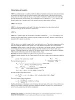
7-89 EES Prob. 7-88 is reconsidered. The thickness of the insulation as a function of the maximum
temperature of the outer surface of insulation is to be plotted.
Analysis The problem is solved using EES, and the solution is given below.
"GIVEN"
T_i=110 [C]
T_o=22 [C]
k_pipe=52 [W/m-C]
r_1=0.02 [m]
t_pipe=0.003 [m]
T_s_max=30 [C]
h_i=80 [W/m^2-C]
h_o=22 [W/m^2-C]
k_ins=0.038 [W/m-C]
"ANALYSIS"
L=1 [m] “1 m long section of the pipe is considered"
A_i=2*pi*r_1*L
A_o=2*pi*r_3*L
r_3=r_2+t_ins*Convert(cm, m) "t_ins is in cm"
r_2=r_1+t_pipe
R_conv_i=1/(h_i*A_i)
R_pipe=ln(r_2/r_1)/(2*pi*k_pipe*L)
R_ins=ln(r_3/r_2)/(2*pi*k_ins*L)
R_conv_o=1/(h_o*A_o)
R_total=R_conv_i+R_pipe+R_ins+R_conv_o
Q_dot=(T_i-T_o)/R_total
Q_dot=(T_s_max-T_o)/R_conv_o
tins [cm]
4.45
2.489
1.733
1.319
1.055
0.871
0.7342
0.6285
0.5441
0.4751
0.4176
0.3688
0.327
4.5
4
3.5
3
t ins [cm ]
Ts, max [C]
24
26
28
30
32
34
36
38
40
42
44
46
48
2.5
2
1.5
1
0.5
0
20
25
30
35
40
45
50
T s,m ax [C]
PROPRIETARY MATERIAL. © 2007 The McGraw-Hill Companies, Inc. Limited distribution permitted only to teachers and
educators for course preparation. If you are a student using this Manual, you are using it without permission.
7-69
7-90 A cylindrical oven is to be insulated to reduce heat losses. The optimum thickness of insulation and
the amount of money saved per year are to be determined.
Assumptions 1 Steady operating conditions exist. 2 Heat transfer through the insulation is onedimensional. 3 Thermal conductivities are constant. 4 The thermal contact resistance at the interface is
negligible. 5 The surface temperature of the furnace and the heat transfer coefficient remain constant. 6 The
surfaces of the cylindrical oven can be treated as plain surfaces since its diameter is greater than 1 m.
Properties The thermal conductivity of insulation is given to be k = 0.038 W/m⋅°C.
Analysis We treat the surfaces of this cylindrical furnace as plain surfaces since its diameter is greater than
1 m, and disregard the curvature effects. The exposed surface area of the furnace is
Ao = 2 Abase + Aside = 2πr 2 + 2πrL = 2π (1.5 m) 2 + 2π (1.5 m)(6 m) = 70.69 m 2
The rate of heat loss from the furnace before the insulation is installed is
Q& = ho Ao (Ts − T∞ ) = (30 W/m 2 .°C)(70.69 m 2 )(90 − 27)°C = 133,600 W
Noting that the plant operates 52×80 = 4160 h/yr, the
Rinsulation
Ro
annual heat lost from the furnace is
T
9
s
T∞
&
Q = QΔt = (133.6 kJ/s)(4160 × 3600 s/yr) = 2.001 × 10 kJ/yr
The efficiency of the furnace is given to be 78 percent. Therefore, to generate this much heat, the furnace
must consume energy (in the form of natural gas) at a rate of
Qin = Q / η oven = (2.001 × 10 9 kJ/yr)/0.78 = 2.565 × 10 9 kJ/yr = 24,314 therms/yr
since 1 therm = 105,500 kJ. Then the annual fuel cost of this furnace before insulation becomes
Annual Cost = Q in × Unit cost = (24,314 therm/yr)($0.50/therm) = $12,157/yr
We expect the surface temperature of the furnace to increase, and the heat transfer coefficient to decrease
somewhat when insulation is installed. We assume these two effects to counteract each other. Then the rate
of heat loss for 1-cm thick insulation becomes
T − T∞
T s − T∞
A (T − T∞ )
(70.69 m 2 )(90 − 27)°C
Q& ins = s
=
= o s
=
= 15,021 W
0.01 m
1
t ins
1
R total
Rins + Rconv
+
+
0.038 W/m.°C 30 W/m 2 .°C
k ins ho
Also, the total amount of heat loss from the furnace per year and the amount and cost of energy
consumption of the furnace become
Qins = Q& ins Δt = (15.021 kJ/s)(4160 × 3600 s/yr) = 2.249 × 10 8 kJ/yr
Qin,ins = Qins / η oven = (2.249 × 10 8 kJ/yr)/0.78 = 2.884 × 10 8 kJ/yr = 2734 therms
Annual Cost = Q in,ins × Unit cost = (2734 therm/yr)($0.50/therm) = $1367/yr
Cost savings = Energy cost w/o insulation − Energy cost w/insulation = 12,157 − 1367 = $10,790/yr
The unit cost of insulation is given to be $10/m2 per cm thickness, plus $30/m2 for labor. Then the total
cost of insulation becomes
Insulation Cost = ( Unit cost)(Surface area) = [($10/cm)(1 cm) + $30/m 2 ](70.69 m 2 ) = $2828
To determine the thickness of insulation whose cost is equal to annual energy savings, we repeat the
calculations above for 2, 3, . . . . 15 cm thick insulations, and list the results in the table below.
Insulation
thickness
0 cm
1 cm
5 cm
10 cm
11 cm
12 cm
13 cm
14 cm
15 cm
Rate of heat loss
W
133,600
15,021
3301
1671
1521
1396
1289
1198
1119
Cost of heat lost
$/yr
12,157
1367
300
152
138
127
117
109
102
Cost savings
$/yr
0
10,790
11,850
12,005
12,019
12,030
12,040
12,048
12,055
Insulation cost $
0
2828
3535
9189
9897
10,604
11,310
12,017
12,724
Therefore, the thickest insulation that will pay for itself in one year is the one whose thickness is 14 cm.
PROPRIETARY MATERIAL. © 2007 The McGraw-Hill Companies, Inc. Limited distribution permitted only to teachers and
educators for course preparation. If you are a student using this Manual, you are using it without permission.
7-70
7-91 A cylindrical oven is to be insulated to reduce heat losses. The optimum thickness of insulation and
the amount of money saved per year are to be determined.
Assumptions 1 Steady operating conditions exist. 2 Heat transfer through the insulation is onedimensional. 3 Thermal conductivities are constant. 4 The thermal contact resistance at the interface is
negligible. 5 The surface temperature of the furnace and the heat transfer coefficient remain constant. 6 The
surfaces of the cylindrical oven can be treated as plain surfaces since its diameter is greater than 1 m.
Properties The thermal conductivity of insulation is given to be k = 0.038 W/m⋅°C.
Analysis We treat the surfaces of this cylindrical furnace as plain surfaces since its diameter is greater than
1 m, and disregard the curvature effects. The exposed surface area of the furnace is
Ao = 2 Abase + Aside = 2πr 2 + 2πrL = 2π (1.5 m) 2 + 2π (1.5 m)(6 m) = 70.69 m 2
The rate of heat loss from the furnace before the insulation is installed is
Q& = ho Ao (Ts − T∞ ) = (30 W/m 2 .°C)(70.69 m 2 )(75 − 27)°C = 101,794 W
Noting that the plant operates 52×80 = 4160 h/yr, the
annual heat lost from the furnace is
Q = Q& Δt = (101.794 kJ/s)(4160 × 3600 s/yr) = 1.524 × 10 9 kJ/yr
Rinsulation
Ro
The efficiency of the furnace is given to be 78 percent.
Ts
T∞
Therefore, to generate this much heat, the furnace must
consume energy (in the form of natural gas) at a rate of
Qin = Q / η oven = (1.524 × 10 9 kJ/yr)/0.78 = 1.954 × 10 9 kJ/yr = 18,526 therms/yr
since 1 therm = 105,500 kJ. Then the annual fuel cost of this furnace before insulation becomes
Annual Cost = Q in × Unit cost = (18,526 therm/yr)($0.50/therm) = $9,263/yr
We expect the surface temperature of the furnace to increase, and the heat transfer coefficient to decrease
somewhat when insulation is installed. We assume these two effects to counteract each other. Then the rate
of heat loss for 1-cm thick insulation becomes
T − T∞
T s − T∞
A (T − T∞ )
(70.69 m 2 )(75 − 27)°C
Q& ins = s
=
= o s
=
= 11,445 W
0.01 m
1
t ins
1
R total
Rins + Rconv
+
+
0.038 W/m.°C 30 W/m 2 .°C
k ins ho
Also, the total amount of heat loss from the furnace per year and the amount and cost of energy
consumption of the furnace become
Qins = Q& ins Δt = (11.445 kJ/s)(4160 × 3600 s/yr) = 1.714 × 10 8 kJ/yr
Qin,ins = Qins / η oven = (1.714 × 10 8 kJ/yr)/0.78 = 2.197 × 10 8 kJ/yr = 2082 therms
Annual Cost = Qin,ins × Unit cost = (2082 therm/yr)($0.50/therm) = $1041/yr
Cost savings = Energy cost w/o insulation − Energy cost w/insulation = 9263 − 1041 = $8222/yr
The unit cost of insulation is given to be $10/m2 per cm thickness, plus $30/m2 for labor. Then the total
cost of insulation becomes
Insulation Cost = ( Unit cost)(Surface area) = [($10/cm)(1 cm) + $30/m 2 ](70.69 m 2 ) = $2828
To determine the thickness of insulation whose cost is equal to annual energy savings, we repeat the
calculations above for 2, 3, . . . . 15 cm thick insulations, and list the results in the table below.
Insulation
Rate of heat loss
Cost of heat lost
Cost savings
Insulation cost
Thickness
W
$/yr
$/yr
$
0 cm
101,794
9263
0
0
1 cm
11,445
1041
8222
2828
5 cm
2515
228
9035
3535
9 cm
1413
129
9134
8483
10 cm
1273
116
9147
9189
11 cm
1159
105
9158
9897
12 cm
1064
97
9166
10,604
Therefore, the thickest insulation that will pay for itself in one year is the one whose thickness is 9 cm. The
10-cm thick insulation will come very close to paying for itself in one year.
PROPRIETARY MATERIAL. © 2007 The McGraw-Hill Companies, Inc. Limited distribution permitted only to teachers and
educators for course preparation. If you are a student using this Manual, you are using it without permission.
7-71
7-92E Steam is flowing through an insulated steel pipe, and it is proposed to add another 1-in thick layer
of fiberglass insulation on top of the existing one to reduce the heat losses further and to save energy and
money. It is to be determined if the new insulation will pay for itself within 2 years.
Assumptions 1 Heat transfer is steady since there is no indication of any change with time. 2 Heat transfer
is one-dimensional since there is thermal symmetry about the centerline and no variation in the axial
direction. 3 Thermal properties are constant. 4 The heat transfer coefficients remain constant. 5 The
thermal contact resistance at the interface is negligible.
Properties The thermal conductivities are given to be k = 8.7 Btu/h⋅ft⋅°F for steel pipe and k = 0.020
Btu/h⋅ft⋅°F for fiberglass insulation.
Analysis The inner radius of the pipe is r1 = 1.75 in, the outer radius of the pipe is r2 = 2 in, and the outer
radii of the existing and proposed insulation layers are r3 = 3 in and 4 in, respectively. Considering a unit
pipe length of L = 1 ft, the individual thermal resistances are determined to be
Rpipe
Ri
Rinsulation
Ro
To
Ti
T1
T3
1
1
1
=
=
= 0.0364 h.°F/Btu
2
hi A1 hi (2πr1 L) (30 Btu/h.ft .°F)[2π (1.75/12 ft)(1 ft)]
Ri = Rconv,1 =
R1 = R pipe =
T2
ln(r2 / r1 )
ln(2 / 1.75)
=
= 0.00244 h.°F/Btu
2πk1 L
2π (8.7 Btu/h.ft.°F)(1 ft )
Current Case:
Rinsulation =
ln(r3 / r2 )
ln(3 / 2)
=
= 3.227 h.°F/Btu
2πk ins L
2π (0.020 Btu/h.ft.°F)(1 ft )
Ro = Rconv,2 =
1
1
1
=
=
= 0.1273 h.°F/Btu
ho A3 ho (2πr3 ) (5 Btu/h.ft 2 .°F)[2π (3 / 12 ft)(1 ft )]
Then the steady rate of heat loss from the steam becomes
Ti − T o
(300 − 85)°F
ΔT
Q& current =
=
=
= 63.36 Btu/h
R total Ri + R pipe + Rins + Ro (0.0364 + 0.00244 + 3.227 + 0.1273) h.°F/Btu
Proposed Case:
Rinsulation =
ln(r3 / r2 )
ln(4 / 2)
=
= 5.516 h.°F/Btu
2πk ins L
2π (0.020 Btu/h.ft.°F)(1 ft )
Ro = Rconv,2 =
1
1
1
=
=
= 0.0955 h.°F/Btu
ho A3 ho (2πr3 ) (5 Btu/h.ft 2 .°F)[2π (4 / 12 ft)(1 ft )]
Then the steady rate of heat loss from the steam becomes
Ti − To
(300 − 85)°F
ΔT
Q& prop =
=
=
= 38.05 Btu/h
R total Ri + R pipe + Rins + Ro (0.0364 + 0.00244 + 5.516 + 0.0955) h.°F/Btu
Therefore, the amount of energy and money saved by the additional insulation per year are
Q&
= Q&
− Q&
= 63.36 − 38.05 = 25.31 Btu/h
saved
Qsaved
prop
current
= Q& saved Δt = (25.31 Btu/h )(8760 h/yr) = 221,700 Btu/yr
Money saved = Qsaved × ( Unit cost ) = (221,700 Btu/yr)($0.01 / 1000 Btu ) = $2.22 / yr
or $4.44 per 2 years, which is less than the $7.0 minimum required. Therefore, the criterion is not satisfied,
and the proposed additional insulation is not justified.
PROPRIETARY MATERIAL. © 2007 The McGraw-Hill Companies, Inc. Limited distribution permitted only to teachers and
educators for course preparation. If you are a student using this Manual, you are using it without permission.
7-72
7-93 The plumbing system of a plant involves some section of a plastic pipe exposed to the ambient air.
The pipe is to be insulated with adequate fiber glass insulation to prevent freezing of water in the pipe. The
thickness of insulation that will protect the water from freezing under worst conditions is to be determined.
Assumptions 1 Heat transfer is transient, but can be treated as steady at average conditions. 2 Heat transfer
is one-dimensional since there is thermal symmetry about the centerline and no variation in the axial
direction. 3 Thermal properties are constant. 4 The water in the pipe is stationary, and its initial temperature
is 15°C. 5 The thermal contact resistance at the interface is negligible. 6 The convection resistance inside
the pipe is negligible.
Properties The thermal conductivities are given to be k = 0.16 W/m⋅°C for plastic pipe and k = 0.035
W/m⋅°C for fiberglass insulation. The density and specific heat of water are ρ = 1000 kg/m3 and cp = 4.18
kJ/kg.°C (Table A-15).
Analysis The inner radius of the pipe is r1 = 3.0 cm and the outer radius of the pipe and thus the inner
radius of insulation is r2 = 3.3 cm. We let r3 represent the outer radius of insulation. Considering a 1-m
section of the pipe, the amount of heat that must be transferred from the water as it cools from 15 to 0°C is
determined to be
m = ρV = ρ (πr12 L) = (1000 kg/m 3 )[π (0.03 m) 2 (1 m)] = 2.827 kg
Q total = mc p ΔT = (2.827 kg)(4.18 kJ/kg.°C)(15 − 0)°C = 177.3 kJ
Then the average rate of heat transfer
during 60 h becomes
Ri ≈ 0
Rpipe
Rinsulation
Ro
To
Ti
Q
177,300 J
Q& ave = total =
= 0.821 W
Δt
(60 × 3600 s)
T1
T2
T3
The individual thermal resistances are
R1 = R pipe =
Rinsulation =
ln(r2 / r1 )
ln(0.033 / 0.03)
=
= 0.0948 °C/W
2πk pipe L 2π (0.16 W/m.°C)(1 m)
ln(r3 / r2 )
ln(r3 / 0.033)
=
= 4.55 ln(r3 / 0.033) °C/W
2πk 2 L
2π (0.035 W/m.°C)(1 m)
Ro = Rconv =
1
1
1
=
=
°C/W
ho A3 (30 W/m 2 .°C)(2πr3 m 2 ) 188.5r3
Then the rate of average heat transfer from the water can be expressed as
Q& =
Ti , ave − To
R total
→ 0.821 W =
[7.5 − (−10)]°C
→ r3 = 3.50 m
[0.0948 + 4.55 ln(r3 / 0.033) + 1 /(188.5r3 )]°C/W
Therefore, the minimum thickness of fiberglass needed to protect the pipe from freezing is
t = r3 - r2 = 3.50 − 0.033 = 3.467 m
which is too large. Installing such a thick insulation is not practical, however, and thus other freeze
protection methods should be considered.
PROPRIETARY MATERIAL. © 2007 The McGraw-Hill Companies, Inc. Limited distribution permitted only to teachers and
educators for course preparation. If you are a student using this Manual, you are using it without permission.
7-73
7-94 The plumbing system of a plant involves some section of a plastic pipe exposed to the ambient air.
The pipe is to be insulated with adequate fiber glass insulation to prevent freezing of water in the pipe. The
thickness of insulation that will protect the water from freezing more than 20% under worst conditions is to
be determined.
Assumptions 1 Heat transfer is transient, but can be treated as steady at average conditions. 2 Heat transfer
is one-dimensional since there is thermal symmetry about the centerline and no variation in the axial
direction. 3 Thermal properties are constant. 4 The water in the pipe is stationary, and its initial temperature
is 15°C. 5 The thermal contact resistance at the interface is negligible. 6 The convection resistance inside
the pipe is negligible.
Properties The thermal conductivities are given to be k = 0.16 W/m⋅°C for plastic pipe and k = 0.035
W/m⋅°C for fiberglass insulation. The density and specific heat of water are ρ = 1000 kg/m3 and Cp = 4.18
kJ/kg.°C (Table A-15). The latent heat of freezing of water is 333.7 kJ/kg.
Analysis The inner radius of the pipe is r1 = 3.0 cm and the outer radius of the pipe and thus the inner
radius of insulation is r2 = 3.3 cm. We let r3 represent the outer radius of insulation. Considering a 1-m
section of the pipe, the amount of heat that must be transferred from the water as it cools from 15 to 0°C is
determined to be
m = ρV = ρ (πr12 L) = (1000 kg/m 3 )[π (0.03 m) 2 (1 m)] = 2.827 kg
Q total = mc p ΔT = (2.827 kg)(4.18 kJ/kg.°C)(15 - 0)°C = 177.3 kJ
Qfreezing = 0.2 × mhif = 0.2 × (2.827 kg )(333.7 kJ/kg ) = 188.7 kJ
Q total = Qcooling + Qfreezing = 177.3 + 188.7 = 366.0 kJ
Then the average rate of heat
transfer during 60 h becomes
Ri ≈ 0
Q
366,000 J
Q& avg = total =
= 1.694 W
Δt
(60 × 3600 s)
Rinsulation =
Rinsulation
Ro
To
T1
The individual thermal resistances are
R1 = R pipe =
Rpipe
Ti
T2
T3
ln(r2 / r1 )
ln(0.033 / 0.03)
=
= 0.0948 °C/W
2πk pipe L 2π (0.16 W/m.°C)(1 m)
ln(r3 / r2 )
ln(r3 / 0.033)
=
= 4.55 ln(r3 / 0.033) °C/W
2πk 2 L
2π (0.035 W/m.°C)(1 m)
R o = R conv =
1
1
1
=
=
°C/W
2
2
ho A3 (30 W/m .°C)(2πr3 m ) 188.5r3
Then the rate of average heat transfer from the water can be expressed as
Q& =
Ti ,avg − To
R total
→ 1.694 W =
[7.5 − (−10)]°C
→ r3 = 0.312 m
[0.0948 + 4.55 ln(r3 / 0.033) + 1 /(188.5r3 )]°C/W
Therefore, the minimum thickness of fiberglass needed to protect the pipe from freezing is
t = r3 - r2 = 0.312 − 0.033 = 0.279 m
which is too large. Installing such a thick insulation is not practical, however, and thus other freeze
protection methods should be considered.
PROPRIETARY MATERIAL. © 2007 The McGraw-Hill Companies, Inc. Limited distribution permitted only to teachers and
educators for course preparation. If you are a student using this Manual, you are using it without permission.
7-74
Review Problems
7-95 Wind is blowing parallel to the walls of a house. The rate of heat loss from the wall is to be
determined.
Assumptions 1 Steady operating conditions exist. 2 The critical Reynolds number is Recr = 5×10⁵. 3
Radiation effects are negligible. 4 Air is an ideal gas with constant properties. 5 The pressure of air is 1
atm.
Properties Assuming a film temperature of Tf = 10°C for the
outdoors, the properties of air are evaluated to be (Table A-15)
k = 0.02439 W/m.°C
T∞1 = 22°C
Air
V = 50 km/h
T∞2 = 6°C
ν = 1.426 × 10 -5 m 2 /s
Pr = 0.7336
Analysis Air flows along 8-m side. The
Reynolds number in this case is
Re L =
VL
ν
=
WALL
[(50 ×1000 / 3600) m/s](8 m) = 7.792 ×10 6
1.426 ×10 −5 m 2 /s
L=8m
which is greater than the critical Reynolds number. Thus we have
combined laminar and turbulent flow. Using the proper relation for
Nusselt number, heat transfer coefficient is determined to be
[
]
ho L
= (0.037 Re L 0.8 − 871) Pr 1 / 3 = 0.037(7.792 × 10 6 ) 0.8 − 871 (0.7336)1 / 3 = 10,096
k
k
0.02439 W/m.°C
ho = Nu =
(10,096) = 30.78 W/m 2 .°C
L
8m
Nu =
The thermal resistances are
As = wL = (4 m)(8 m) = 32 m
Ri =
Rinsulation =
Ro =
Ri
2
Rinsulation
Ro
T∞1
T∞2
1
1
=
= 0.0039 °C/W
2
hi As (8 W/m .°C)(32 m 2 )
( R − 3.38) value 3.38 m 2 .°C/W
=
= 0.1056 °C/W
As
32 m 2
1
1
=
= 0.0010 °C/W
ho As (30.78 W/m 2 .°C)(32 m 2 )
Then the total thermal resistance and the heat transfer rate through the wall are determined from
Rtotal = Ri + Rinsulation + Ro = 0.0039 + 0.1056 + 0.0010 = 0.1105 °C/W
T −T
(22 − 6)°C
Q& = ∞1 ∞ 2 =
= 145 W
Rtotal
0.1105 °C/W
PROPRIETARY MATERIAL. © 2007 The McGraw-Hill Companies, Inc. Limited distribution permitted only to teachers and
educators for course preparation. If you are a student using this Manual, you are using it without permission.
7-75
7-96 A car travels at a velocity of 60 km/h. The rate of heat transfer from the bottom surface of the hot
automotive engine block is to be determined for two cases.
Assumptions 1 Steady operating conditions exist. 2 The critical Reynolds number is Recr = 5×10⁵. 3 Air is
an ideal gas with constant properties. 4 The pressure of air is 1 atm. 5 The flow is turbulent over the entire
surface because of the constant agitation of the engine block. 6 The bottom surface of the engine is a flat
surface.
Properties The properties of air at 1 atm and the film
temperature of (Ts + T∞)/2 = (75+5)/2 = 40°C are (Table A-15)
L = 0.7 m
k = 0.02662 W/m.°C
-5
Engine block
2
ν = 1.702 × 10 m /s
Air
V = 60 km/h
T∞ = 5°C
Pr = 0.7255
Analysis The Reynolds number is
Re L =
VL
ν
=
[(60 ×1000 / 3600) m/s](0.7 m) = 6.855 ×10 5
Ts = 75°C
ε = 0.92
Ts = 10°C
1.702 × 10 −5 m 2 /s
which is less than the critical Reynolds number. But we
will assume turbulent flow because of the constant
agitation of the engine block.
hL
= 0.037 Re L 0.8 Pr 1 / 3 = 0.037(6.855 × 10 5 ) 0.8 (0.7255)1 / 3 = 1551
k
k
0.02662 W/m.°C
h = Nu =
(1551) = 58.97 W/m 2 .°C
L
0.7 m
Nu =
Q& conv = hAs (T∞ − Ts ) = (58.97 W/m 2 .°C)[(0.6 m)(0.7 m)](75 − 5)°C = 1734 W
The heat loss by radiation is then determined from Stefan-Boltzman law to be
4
Q& rad = εAs σ (Ts4 − Tsurr
)
[
]
= (0.92)(0.6 m)(0.7 m)(5.67 ×10 -8 W/m 2 .K 4 ) (75 + 273 K) 4 − (10 + 273 K) 4 = 181 W
Then the total rate of heat loss from the bottom surface of the engine block becomes
Q& total = Q& conv + Q& rad = 1734 + 181 = 1915 W
The gunk will introduce an additional resistance to heat dissipation from the engine. The total heat transfer
rate in this case can be calculated from
T∞ − Ts
(75 - 5)°C
Q& =
= 1668 W
=
1
(0.002 m)
L
1
+
+
hAs kAs
(58.97 W/m 2 .°C)[(0.6 m)(0.7 m)] (3 W/m.°C)(0.6 m × 0.7 m)
The decrease in the heat transfer rate is
1734 − 1668 = 66 W (3.8%)
PROPRIETARY MATERIAL. © 2007 The McGraw-Hill Companies, Inc. Limited distribution permitted only to teachers and
educators for course preparation. If you are a student using this Manual, you are using it without permission.
7-76
7-97E A minivan is traveling at 60 mph. The rate of heat transfer to the van is to be determined.
Assumptions 1 Steady operating conditions exist. 2 The critical Reynolds number is Recr = 5×10⁵. 3
Radiation effects are negligible. 4 Air flow is turbulent because of the intense vibrations involved. 5 Air is
an ideal gas with constant properties. 5 The pressure of air is 1 atm.
Properties Assuming a film temperature of Tf = 80°F, the
properties of air are evaluated to be (Table A-15E)
Air
V = 60 mph
T∞ = 90°F
k = 0.01481 Btu/h.ft.°F
Minivan
ν = 1.697 × 10 - 4 ft 2 /s
Pr = 0.7290
Analysis Air flows along 11 ft long side. The
Reynolds number in this case is
Re L =
VL
ν
=
[(60 × 5280 / 3600) ft/s](11 ft)
1.697 × 10
−4
2
ft /s
L = 11 ft
= 5.704 × 10 6
which is greater than the critical Reynolds number. The air flow is assumed to be entirely turbulent because
of the intense vibrations involved. Then the Nusselt number and the heat transfer coefficient are
determined to be
ho L
= 0.037 Re L 0.8 Pr 1 / 3 = 0.037(5.704 × 10 6 ) 0.8 (0.7290)1 / 3 = 8461
k
k
0.01481 Btu/h.ft.°F
ho = Nu =
(8461) = 11.39 Btu/h.ft 2 .°F
L
11 ft
Ri
Rinsulation
Nu =
The thermal resistances are
Ro
T∞1
T∞2
As = 2[(3.2 ft)(6 ft) + (3.2 ft)(11 ft) + (6 ft)(11 ft)] = 240.8 ft 2
Ri =
1
1
=
= 0.0035 h.°F/Btu
2
hi As (1.2 Btu/h.ft .°F)(240.8 ft 2 )
( R − 3) value 3 h.ft 2 .°F/Btu
=
= 0.0125 h.°F/Btu
As
(240.8 ft 2 )
1
1
Ro =
=
= 0.0004 h.°F/Btu
ho As (11.39 Btu/h.ft 2 .°F)(240.8 ft 2 )
Rinsulation =
Then the total thermal resistance and the heat transfer rate into the minivan are determined to be
Rtotal = Ri + Rinsulation + Ro = 0.0035 + 0.0125 + 0.0004 = 0.0164 h.°F/Btu
T − T∞1
(90 − 70)°F
Q& = ∞ 2
=
= 1220 Btu/h
Rtotal
0.0164 h.°F/Btu
PROPRIETARY MATERIAL. © 2007 The McGraw-Hill Companies, Inc. Limited distribution permitted only to teachers and
educators for course preparation. If you are a student using this Manual, you are using it without permission.
7-77
7-98 Wind is blowing parallel to the walls of a house with windows. The rate of heat loss through the
window is to be determined.
Assumptions 1 Steady operating conditions exist. 2 The critical Reynolds number is Recr = 5×10⁵. 3
Radiation effects are negligible. 4 Air is an ideal gas with constant properties. 5 The pressure of air is 1
atm.
Properties Assuming a film temperature of 5°C, the
properties of air at 1 atm and this temperature are
evaluated to be (Table A-15)
k = 0.02401 W/m.°C
ν = 1.382 × 10 -5 m 2 /s
T∞1 = 22°C
Air
V = 35 km/h
T∞2 = -2°C
WINDOW
Pr = 0.7350
Analysis Air flows along 1.8 m side. The Reynolds
number in this case is
Re L =
VL
ν
=
[(35 ×1000 / 3600) m/s](1.8 m) = 1.266 ×10 6
1.382 × 10
−5
L = 1.8 m
2
m /s
which is greater than the critical Reynolds number. Thus we have combined laminar and turbulent flow.
Using the proper relation for Nusselt number, heat transfer coefficient is determined to be
[
]
hL
= (0.037 Re L 0.8 − 871) Pr 1 / 3 = 0.037(1.266 × 10 6 ) 0.8 − 871 (0.7350)1 / 3 = 1759
k
k
0.02401 W/m.°C
h = Nu =
(1759) = 23.46 W/m 2 .°C
L
1. 8 m
Nu =
Ri
The thermal resistances are
As = 3(1.8 m)(1.5 m) = 8.1 m 2
Rcond
Ro
T∞1
T∞2
1
1
=
= 0.0154 °C/W
2
hi As (8 W/m .°C)(8.1 m 2 )
0.005 m
L
=
=
= 0.0008 °C/W
kAs (0.78 W/m.°C)(8.1 m 2 )
R conv,i =
Rcond
Rconv,o =
1
1
=
= 0.0053 °C/W
ho As (23.46 W/m 2 .°C)(8.1 m 2 )
Then the total thermal resistance and the heat transfer rate through the 3 windows become
Rtotal = Rconv,i + Rcond + Rconv,o = 0.0154 + 0.0008 + 0.0053 = 0.0215 °C/W
T −T
[22 − (−2)]°C
= 1116 W
Q& = ∞1 ∞ 2 =
Rtotal
0.0215 °C/W
PROPRIETARY MATERIAL. © 2007 The McGraw-Hill Companies, Inc. Limited distribution permitted only to teachers and
educators for course preparation. If you are a student using this Manual, you are using it without permission.
7-78
7-99 A fan is blowing air over the entire body of a person. The average temperature of the outer surface of
the person is to be determined.
Assumptions 1 Steady operating conditions exist. 2 Air is an ideal gas with constant properties. 3 The
pressure of air is 1 atm. 4 The average human body can be treated as a 30-cm-diameter cylinder with an
exposed surface area of 1.7 m2.
Properties We assume the film temperature to be 35°C. The
properties of air at 1 atm and this temperature are (Table A-15)
k = 0.02625 W/m.°C
ν = 1.655 × 10 -5 m 2 /s
Person, Ts
90 W
ε = 0.9
V = 5 m/s
T∞ = 32°C
Pr = 0.7268
D=0.3 m
Analysis The Reynolds number is
Re =
VD
ν
=
(5 m/s)(0.3 m)
1.655 × 10
−5
2
m /s
= 9.063 × 10 4
The proper relation for Nusselt number corresponding to this Reynolds number is
hD
0.62 Re 0.5 Pr 1 / 3
Nu =
= 0.3 +
1/ 4
k
1 + (0.4 / Pr )2 / 3
[
]
⎡ ⎛ Re ⎞ 5 / 8 ⎤
⎢1 + ⎜⎜
⎟⎟ ⎥
⎢⎣ ⎝ 282,000 ⎠ ⎥⎦
4/5
⎡
0.62(9.063 × 10 4 ) 0.5 (0.7268)1 / 3 ⎢ ⎛⎜ 9.063 × 10 4
= 0.3 +
1+
1/ 4
⎢ ⎜⎝ 282,000
1 + (0.4 / 0.7268)2 / 3
⎣
[
]
⎞
⎟
⎟
⎠
5/8 ⎤
⎥
⎥
⎦
4/5
= 203.6
Then
h=
k
0.02655 W/m.°C
Nu =
( 203.6) = 18.02 W/m 2 .°C
D
0. 3 m
Considering that there is heat generation in that person's body at a rate of 90 W and body gains heat by
radiation from the surrounding surfaces, an energy balance can be written as
Q&
+ Q&
= Q&
generated
radiation
convection
Substituting values with proper units and then application of trial & error method or the use of an equation
solver yields the average temperature of the outer surface of the person.
4
90 W + εAs σ (Tsurr
− Ts4 ) = hAs (Ts − T∞ )
90 + (0.9)(1.7)(5.67 ×10 −8 )[(40 + 273) 4 − Ts 4 ] = (18.02)(1.7)[Ts − (32 + 273)]
⎯
⎯→ Ts = 309.2 K = 36.2°C
PROPRIETARY MATERIAL. © 2007 The McGraw-Hill Companies, Inc. Limited distribution permitted only to teachers and
educators for course preparation. If you are a student using this Manual, you are using it without permission.
7-79
7-100 The heat generated by four transistors mounted on a thin vertical plate is dissipated by air blown
over the plate on both surfaces. The temperature of the aluminum plate is to be determined.
Assumptions 1 Steady operating conditions exist. 2 The critical Reynolds number is Recr = 5×10⁵. 3
Radiation effects are negligible. 4 The entire plate is nearly isothermal. 5 The exposed surface area of the
transistor is taken to be equal to its base area. 6 Air is an ideal gas with constant properties. 7 The pressure
of air is 1 atm.
Properties Assuming a film temperature
of 40°C, the properties of air are
evaluated to be (Table A-15)
V = 250 m/min
T∞ = 20°C
12 W
k = 0.02662 W/m.°C
-5
Ts
2
ν = 1.702 × 10 m /s
L= 22 cm
Pr = 0.7255
Analysis The Reynolds number in this case is
Re L =
VL
ν
=
[(250 / 60) m/s](0.22 m) = 5.386 ×10 4
1.702 × 10 −5 m 2 /s
which is smaller than the critical Reynolds number. Thus we have laminar flow. Using the proper relation
for Nusselt number, heat transfer coefficient is determined to be
hL
= 0.664 Re L 0.5 Pr 1 / 3 = 0.664(5.386 × 10 4 ) 0.5 (0.7255) 1 / 3 = 138.5
k
k
0.02662 W/m.°C
h = Nu =
(138.5) = 16.75 W/m 2 .°C
L
0.22 m
Nu =
The temperature of aluminum plate then becomes
(4 ×12) W
Q&
= 50.0°C
Q& = hAs (Ts − T∞ ) ⎯
⎯→ Ts = T∞ +
= 20°C +
hAs
(16.75 W/m 2 .°C)[2(0.22 m) 2 ]
Discussion In reality, the heat transfer coefficient will be higher since the transistors will cause turbulence
in the air.
PROPRIETARY MATERIAL. © 2007 The McGraw-Hill Companies, Inc. Limited distribution permitted only to teachers and
educators for course preparation. If you are a student using this Manual, you are using it without permission.
7-80
7-101 A spherical tank used to store iced water is subjected to winds. The rate of heat transfer to the iced
water and the amount of ice that melts during a 24-h period are to be determined.
Assumptions 1 Steady operating conditions exist. 2 Thermal resistance of the tank is negligible. 3
Radiation effects are negligible. 4 Air is an ideal gas with constant properties. 5 The pressure of air is 1
atm.
Properties The properties of air at 1 atm pressure and the free stream temperature of 30°C are (Table A-15)
k = 0.02588 W/m.°C
ν = 1.608 × 10 -5 m 2 /s
Ts = 0°C
V = 25 km/h
T∞ = 30°C
μ ∞ = 1.872 × 10 −5 kg/m.s
μ s , @ 0°C = 1.729 × 10 −5 kg/m.s
Pr = 0.7282
Analysis (a) The Reynolds number is
Re =
VD
ν
=
[(25 ×1000/3600) m/s](3.02 m) = 1.304 ×10 6
1.608 ×10
−5
Q&
2
Di = 3 m
Iced water
0° C
1 cm
m /s
The Nusselt number corresponding to this Reynolds number is determined from
Nu =
[
]
⎛μ
hD
= 2 + 0.4 Re 0.5 + 0.06 Re 2 / 3 Pr 0.4 ⎜⎜ ∞
k
⎝ μs
⎞
⎟
⎟
⎠
1/ 4
[
]
⎛ 1.872 × 10 −5
= 2 + 0.4(1.304 × 10 6 ) 0.5 + 0.06(1.304 × 10 6 ) 2 / 3 (0.7282) 0.4 ⎜⎜
−5
⎝ 1.729 × 10
and
h=
⎞
⎟
⎟
⎠
1/ 4
= 1056
k
0.02588 W/m.°C
Nu =
(1056) = 9.05 W/m 2 .°C
D
3.02 m
The rate of heat transfer to the iced water is
Q& = hAs (Ts − T∞ ) = h(πD 2 )(Ts − T∞ ) = (9.05 W/m 2 .°C)[π (3.02 m) 2 ](30 − 0)°C = 7779 W
(b) The amount of heat transfer during a 24-hour period is
Q = Q& Δt = (7.779 kJ/s)(24 × 3600 s) = 672,000 kJ
Then the amount of ice that melts during this period becomes
Q = mhif ⎯
⎯→ m =
Q
672,000 kJ
=
= 2014 kg
hif
333.7 kJ/kg
PROPRIETARY MATERIAL. © 2007 The McGraw-Hill Companies, Inc. Limited distribution permitted only to teachers and
educators for course preparation. If you are a student using this Manual, you are using it without permission.
7-81
7-102 A spherical tank used to store iced water is subjected to winds. The rate of heat transfer to the iced
water and the amount of ice that melts during a 24-h period are to be determined.
Assumptions 1 Steady operating conditions exist. 2 Air is an ideal gas with constant properties. 7 The
pressure of air is 1 atm.
Properties The properties of air at 1 atm pressure and the free stream temperature of 30°C are (Table A-15)
k = 0.02588 W/m.°C
Ts, out
ν = 1.608 × 10 -5 m 2 /s
0°C
V = 25 km/h
T∞ = 30°C
μ ∞ = 1.872 × 10 −5 kg/m.s
μ s , @ 0°C = 1.729 × 10 −5 kg/m.s
Pr = 0.7282
Analysis (a) The Reynolds number is
Re =
VD
ν
=
Di = 3 m
Iced water
0° C
[(25 ×1000/3600) m/s](3.02 m) = 1.304 ×10 6
1 cm
1.608 × 10 −5 m 2 /s
The Nusselt number corresponding to this Reynolds number is determined from
[
]
⎛μ
hD
= 2 + 0.4 Re 0.5 + 0.06 Re 2 / 3 Pr 0.4 ⎜⎜ ∞
Nu =
k
⎝ μs
[
6 0.5
= 2 + 0.4(1.304 × 10 )
and
h=
⎞
⎟
⎟
⎠
1/ 4
6 2/3
+ 0.06(1.304 × 10 )
](0.7282)
0.4 ⎛
⎜ 1.872 × 10
−5
⎜ 1.729 × 10 −5
⎝
⎞
⎟
⎟
⎠
1/ 4
= 1056
k
0.02588 W/m.°C
Nu =
(1056) = 9.05 W/m 2 .°C
D
3.02 m
In steady operation, heat transfer through the tank by conduction is equal to the heat transfer from the outer
surface of the tank by convection and radiation. Therefore,
Q& = Q&
= Q&
through tank
Q& =
from tank, conv + rad
Ts ,out − Ts ,in
R sphere
where R sphere =
4
= ho Ao (Tsurr − Ts ,out ) + εAo σ (Tsurr
− Ts4,out )
r2 − r1
(1.51 − 1.50) m
=
= 2.342 × 10 −5 °C/W
4πkr1 r2 4π (15 W/m.°C)(1.51 m)(1.50 m)
Ao = πD 2 = π (3.02 m) 2 = 28.65 m 2
Substituting,
Q& =
T s ,out − 0°C
2.34 × 10
−5
= (9.05 W/m 2 .°C)(28.65 m 2 )(30 − Ts ,out )°C
°C/W
+ (0.75)(28.65 m 2 )(5.67 × 10 −8 W/m 2 .K 4 )[(25 + 273 K) 4 − (Ts ,out + 273 K) 4 ]
whose solution is
Ts = 0.25°C and Q& = 10,530 W = 10.53 kW
(b) The amount of heat transfer during a 24-hour period is
Q = Q& Δt = (10.531 kJ/s)(24 × 3600 s) = 909,880 kJ
Then the amount of ice that melts during this period becomes
⎯→ m =
Q = mhif ⎯
Q
909,880 kJ
=
= 2727 kg
333.7 kJ/kg
hif
PROPRIETARY MATERIAL. © 2007 The McGraw-Hill Companies, Inc. Limited distribution permitted only to teachers and
educators for course preparation. If you are a student using this Manual, you are using it without permission.
7-82
7-103E A cylindrical transistor mounted on a circuit board is cooled by air flowing over it. The maximum
power rating of the transistor is to be determined.
Assumptions 1 Steady operating conditions exist. 2 Radiation effects are negligible. 3 Air is an ideal gas
with constant properties. 4 The pressure of air is 1 atm.
Properties The properties of air at 1 atm and the film
temperature of T f = (180 + 120) / 2 = 150°F are (Table A-15)
Air
500 ft/min
120°F
k = 0.01646 Btu/h.ft.°F
ν = 2.099 × 10 - 4 ft 2 /s
Pr = 0.7188
Power
transistor
D = 0.22 in
L = 0.25 in
Analysis The Reynolds number is
Re =
VD
=
ν
(500/60 ft/s)(0.22/12 ft)
2.099 × 10 − 4 ft 2 /s
= 727.9
The Nusselt number corresponding to this Reynolds number is
hD
0.62 Re 0.5 Pr 1 / 3
Nu =
= 0.3 +
1/ 4
k
1 + (0.4 / Pr )2 / 3
[
]
⎡ ⎛ Re ⎞ 5 / 8 ⎤
⎢1 + ⎜⎜
⎟⎟ ⎥
⎢⎣ ⎝ 282,000 ⎠ ⎥⎦
4/5
5/8
0.62(727.9) 0.5 (0.7188)1 / 3 ⎡ ⎛ 727.9 ⎞ ⎤
⎢1 + ⎜⎜
= 0.3 +
⎟⎟ ⎥
1/ 4
⎢⎣ ⎝ 282,000 ⎠ ⎥⎦
1 + (0.4 / 0.7188)2 / 3
[
and
h=
]
4/5
= 13.72
k
0.01646 Btu/h.ft.°F
Nu =
(13.72) = 12.32 Btu/h.ft 2 .°F
D
(0.22 / 12 ft)
Then the amount of power this transistor can dissipate safely becomes
Q& = hA (T − T ) = h(πDL )(T − T )
s
s
∞
s
∞
= (12.32 Btu/h.ft .°F)[π (0.22/12 ft)(0.25/12 ft)](180 − 120)°C
= 0.887 Btu/h = 0.26 W (1 W = 3.412 Btu/h)
2
PROPRIETARY MATERIAL. © 2007 The McGraw-Hill Companies, Inc. Limited distribution permitted only to teachers and
educators for course preparation. If you are a student using this Manual, you are using it without permission.
7-83
7-104 Wind is blowing over the roof of a house. The rate of heat transfer through the roof and the cost of
this heat loss for 14-h period are to be determined.
Assumptions 1 Steady operating conditions exist. 2 The critical Reynolds number is Recr = 5×10⁵. 3 Air is
an ideal gas with constant properties. 4 The pressure of air is 1 atm.
Properties Assuming a film temperature of 10°C,
the properties of air are (Table A-15)
k = 0.02439 W/m.°C
ν = 1.426 × 10 -5 m 2 /s
Air
V = 60 km/h
T∞ = 10°C
Q&
Tsky = 100 K
Pr = 0.7336
Tin = 20°C
Analysis The Reynolds number is
Re L =
VL
ν
=
[(60 ×1000 / 3600) m/s](20 m) = 2.338 ×10 7
1.426 ×10 −5 m 2 /s
which is greater than the critical Reynolds number. Thus we have
combined laminar and turbulent flow. Then the Nusselt number and
the heat transfer coefficient are determined to be
hL
= (0.037 Re L 0.8 − 871) Pr 1 / 3 = [0.037(2.338 × 10 7 ) 0.8 − 871](0.7336)1 / 3 = 2.542 × 10 4
k
k
0.02439 W/m.°C
h = Nu =
(2.542 × 10 4 ) = 31.0 W/m 2 .°C
L
20 m
Nu =
In steady operation, heat transfer from the room to the roof (by convection and radiation) must be equal to
the heat transfer from the roof to the surroundings (by convection and radiation), which must be equal to
the heat transfer through the roof by conduction. That is,
Q& = Q& room to roof, conv + rad = Q& roof, cond = Q& roof to surroundin gs, conv + rad
Taking the inner and outer surface temperatures of the roof to be Ts,in and Ts,out , respectively, the quantities
above can be expressed as
4
Q& room to roof, conv + rad = hi As (Troom − T s ,in ) + εAs σ (Troom
− Ts4,in ) = (5 W/m 2 .°C)(300 m 2 )(20 − Ts ,in )°C
[
+ (0.9)(300 m 2 )(5.67 × 10 −8 W/m 2 .K 4 ) (20 + 273 K) 4 − (Ts ,in + 273 K) 4
Q& roof, cond = kAs
Ts ,in − Ts ,out
L
= (2 W/m.°C)(300 m 2 )
]
Ts ,in − Ts ,out
0.15 m
4
Q& roof to surr, conv + rad = ho As (Ts ,out − Tsurr ) + εAs σ (Ts ,out − Tsurr 4 ) = (31.0 W/m 2 .°C)(300 m 2 )(Ts ,out − 10)°C
[
+ (0.9)(300 m 2 )(5.67 × 10 −8 W/m 2 .K 4 ) (Ts ,out + 273 K) 4 − (100 K) 4
]
Solving the equations above simultaneously gives
Q& = 28,025 W = 28.03 kW,
Ts ,in = 10.6°C, and Ts ,out = 3.5°C
The total amount of natural gas consumption during a 14-hour period is
Q
Q& Δt (28.03 kJ/s )(14 × 3600 s) ⎛ 1 therm ⎞
Q gas = total =
=
⎜⎜ 105,500 kJ ⎟⎟ = 15.75 therms
0.85 0.85
0.85
⎝
⎠
Finally, the money lost through the roof during that period is
Money lost = (15.75 therms)($1.20 / therm) = $18.9
PROPRIETARY MATERIAL. © 2007 The McGraw-Hill Companies, Inc. Limited distribution permitted only to teachers and
educators for course preparation. If you are a student using this Manual, you are using it without permission.
7-84
7-105 Steam is flowing in a stainless steel pipe while air is flowing across the pipe. The rate of heat loss
from the steam per unit length of the pipe is to be determined.
Assumptions 1 Steady operating conditions exist. 2 Air is an ideal gas with constant properties. 3 The
pressure of air is 1 atm.
Properties Assuming a film temperature of 10°C,
Steel pipe
the properties of air are (Table A-15)
Di = D1 = 4 cm
D2 = 4.6 cm
k = 0.02439 W/m.°C
Insulation
ν = 1.426 × 10 -5 m 2 /s
ε = 0.3
Do
Pr = 0.7336
Di
Analysis The outer diameter of insulated pipe is
Do = 4.6+2×3.5=11.6 cm = 0.116 m. The Reynolds
number is
VDo
(4 m/s)(0.116 m)
Re =
=
= 3.254 × 10 4
ν
1.426 × 10 −5 m 2 /s
Steam, 250°C
The Nusselt number for flow across a cylinder is determined from
hDo
0.62 Re 0.5 Pr 1 / 3
Nu =
= 0.3 +
1/ 4
k
1 + (0.4 / Pr )2 / 3
[
]
⎡ ⎛ Re ⎞ 5 / 8 ⎤
⎢1 + ⎜⎜
⎟⎟ ⎥
⎢⎣ ⎝ 282,000 ⎠ ⎥⎦
4/5
⎡
0.62(3.254 × 10 4 ) 0.5 (0.7336)1 / 3 ⎢ ⎛⎜ 3.254 × 10 4
= 0.3 +
1+
1/ 4
⎢ ⎜⎝ 282,000
1 + (0.4 / 0.7336 )2 / 3
⎣
[
and
ho =
]
⎞
⎟
⎟
⎠
5/8 ⎤
⎥
⎥
⎦
Air
3°C, 4 m/s
4/5
= 107.0
k
0.02439 W/m ⋅ °C
Nu =
(107.0) = 22.50 W/m 2 ⋅ °C
Do
0.116 m
Area of the outer surface of the pipe per m length of the pipe is
Ao = πDo L = π (0.116 m)(1 m) = 0.3644 m 2
In steady operation, heat transfer from the steam through the pipe and the insulation to the outer surface (by
first convection and then conduction) must be equal to the heat transfer from the outer surface to the
surroundings (by simultaneous convection and radiation). That is,
Q& = Q&
= Q&
pipe and insulation
surface to surroundings
Using the thermal resistance network, heat transfer from the steam to the outer surface is expressed as
1
1
=
= 0.0995 °C/W
Rconv,i =
2
hi Ai (80 W/m .°C)[π (0.04 m)(1 m)]
ln(r2 / r1 )
ln(2.3 / 2)
=
= 0.0015 °C/W
2πkL
2π (15 W/m.°C)(1 m)
ln(r3 / r2 )
ln(5.8 / 2.3)
=
=
= 3.874 °C/W
2πkL
2π (0.038 W/m.°C)(1 m)
R pipe =
Rinsulation
and
Q& pipe and ins =
(250 − Ts )°C
T∞1 − T s
=
Rconv ,i + R pipe + Rinsulation (0.0995 + 0.0015 + 3.874) °C/W
Heat transfer from the outer surface can be expressed as
Q&
= h A (T − T ) + εA σ (T 4 − T
surface to surr, conv + rad
o
o
s
surr
o
s
surr
4
) = (22.50 W/m 2 .°C)(0.3644 m 2 )(T s − 3)°C
[
+ (0.3)(0.3644 m 2 )(5.67 × 10 −8 W/m 2 .K 4 ) (T s + 273 K) 4 − (3 + 273 K) 4
]
Solving the two equations above simultaneously, the surface temperature and the heat transfer rate per m
length of the pipe are determined to be
T = 9.9°C and Q& = 60.4 W (per m length)
s
PROPRIETARY MATERIAL. © 2007 The McGraw-Hill Companies, Inc. Limited distribution permitted only to teachers and
educators for course preparation. If you are a student using this Manual, you are using it without permission.
7-85
7-106 A spherical tank filled with liquid nitrogen is exposed to winds. The rate of evaporation of the liquid
nitrogen due to heat transfer from the air is to be determined for three cases.
Assumptions 1 Steady operating conditions exist. 2 Radiation effects are negligible. 3 Air is an ideal gas
with constant properties. 4 The pressure of air is 1 atm.
Properties The properties of air at 1 atm pressure and the free stream temperature of 20°C are (Table A-15)
k = 0.02514 W/m.°C
Insulation
ν = 1.516 × 10 -5 m 2 /s
μ ∞ = 1.825 × 10 −5 kg/m.s
μ s , @ −196 °C = 5.023 × 10 −6 kg/m.s (from EES)
Analysis (a) When there is no insulation,
D = Di = 4 m, and the Reynolds number is
Re =
VD
ν
=
Do
Wind
20°C
40 km/h
Pr = 0.7309
Di
[(40 ×1000/3600) m/s](4 m) = 2.932 ×10 6
1.516 ×10 −5 m 2 /s
Nitrogen tank
-196°C
The Nusselt number is determined from
Nu =
[
]
⎛μ
hD
= 2 + 0.4 Re 0.5 + 0.06 Re 2 / 3 Pr 0.4 ⎜⎜ ∞
k
⎝ μs
⎞
⎟
⎟
⎠
1/ 4
[
]
⎛ 1.825 × 10 −5
= 2 + 0.4(2.932 × 10 6 ) 0.5 + 0.06(2.932 × 10 6 ) 2 / 3 (0.7309) 0.4 ⎜⎜
−6
⎝ 5.023 × 10
and
h=
⎞
⎟
⎟
⎠
1/ 4
= 2333
k
0.02514 W/m.°C
Nu =
(2333) = 14.66 W/m 2 .°C
D
4m
The rate of heat transfer to the liquid nitrogen is
Q& = hAs (Ts − T∞ ) = h(πD 2 )(Ts − T∞ ) = (14.66 W/m 2 .°C)[π (4 m) 2 ][(20 − (−196)] °C = 159,200 W
The rate of evaporation of liquid nitrogen then becomes
Q& 159.2 kJ/s
⎯→ m& =
=
= 0.804 kg/s
Q& = m& hif ⎯
hif
198 kJ/kg
(b) Note that after insulation the outer surface temperature and diameter will change. Therefore we need to
evaluate dynamic viscosity at a new surface temperature which we will assume to be -100°C. At -100°C,
μ = 1.189 ×10 −5 kg/m.s . Noting that D = D0 = 4.1 m, the Nusselt number becomes
[(40 ×1000/3600) m/s](4.1 m) = 3.005 ×10 6
Re =
VD
Nu =
⎛μ
hD
= 2 + 0.4 Re 0.5 + 0.06 Re 2 / 3 Pr 0.4 ⎜⎜ ∞
k
⎝ μs
ν
=
1.516 × 10 −5 m 2 /s
[
]
⎞
⎟
⎟
⎠
1/ 4
[
]
⎛ 1.825 × 10 −5
= 2 + 0.4(3.005 × 10 6 ) 0.5 + 0.06(3.005 × 10 6 ) 2 / 3 (0.7309) 0.4 ⎜⎜
−5
⎝ 1.189 × 10
and
h=
⎞
⎟
⎟
⎠
1/ 4
= 1910
k
0.02514 W/m.°C
Nu =
(1910) = 11.71 W/m 2 .°C
D
4.1 m
The rate of heat transfer to the liquid nitrogen is
PROPRIETARY MATERIAL. © 2007 The McGraw-Hill Companies, Inc. Limited distribution permitted only to teachers and
educators for course preparation. If you are a student using this Manual, you are using it without permission.
7-86
As = πD 2 = π (4.1 m) 2 = 52.81 m 2
Q& =
=
T∞ − Ts , tan k
Rinsulation + Rconv
=
T∞ − Ts , tan k
r2 − r1
1
+
4πkr1 r2 hAs
[20 − (−196)]°C
= 7361 W
(2.05 − 2) m
1
+
4π (0.035 W/m.°C)(2.05 m)(2 m) (11.71 W/m 2 .°C)(52.81 m 2 )
The rate of evaporation of liquid nitrogen then becomes
Q&
7.361 kJ/s
⎯→ m& =
=
= 0.0372 kg/s
Q& = m& hif ⎯
hif
198 kJ/kg
(c) We use the dynamic viscosity value at the new estimated surface temperature of 0°C to be
μ = 1.729 × 10 −5 kg/m.s . Noting that D = D0 = 4.04 m in this case, the Nusselt number becomes
[(40 ×1000/3600) m/s](4.04 m) = 2.961×10 6
Re =
VD
Nu =
⎛μ
hD
= 2 + 0.4 Re 0.5 + 0.06 Re 2 / 3 Pr 0.4 ⎜⎜ ∞
k
⎝ μs
ν
=
1.516 × 10 −5 m 2 /s
[
]
⎞
⎟
⎟
⎠
1/ 4
[
]
⎛ 1.825 × 10 −5
= 2 + 0.4(2.961× 10 6 ) 0.5 + 0.06(2.961× 10 6 ) 2 / 3 (0.7309) 0.4 ⎜⎜
−5
⎝ 1.729 × 10
and
h=
⎞
⎟
⎟
⎠
1/ 4
= 1724
k
0.02514 W/m.°C
Nu =
(1724) = 10.73 W/m 2 .°C
D
4.04 m
The rate of heat transfer to the liquid nitrogen is
As = πD 2 = π (4.04 m) 2 = 51.28 m 2
Q& =
=
T∞ − Ts , tan k
Rinsulation + Rconv
=
T∞ − Ts , tan k
r2 − r1
1
+
4πkr1 r2 hAs
[20 − (−196)]°C
(2.02 − 2) m
1
+
4π (0.00005 W/m.°C)(2.02 m)(2 m) (10.73 W/m 2 .°C)(51.28 m 2 )
= 27.4 W
The rate of evaporation of liquid nitrogen then becomes
Q&
0.0274 kJ/s
⎯→ m& =
=
= 1.38 × 10 - 4 kg/s
Q& = m& hif ⎯
hif
198 kJ/kg
PROPRIETARY MATERIAL. © 2007 The McGraw-Hill Companies, Inc. Limited distribution permitted only to teachers and
educators for course preparation. If you are a student using this Manual, you are using it without permission.
7-87
7-107 A spherical tank filled with liquid oxygen is exposed to ambient winds. The rate of evaporation of
the liquid oxygen due to heat transfer from the air is to be determined for three cases.
Assumptions 1 Steady operating conditions exist. 2 Radiation effects are negligible. 3 Air is an ideal gas
with constant properties. 7 The pressure of air is 1 atm.
Properties The properties of air at 1 atm pressure and the free stream temperature of 20°C are (Table A-15)
k = 0.02514 W/m.°C
ν = 1.516 × 10 -5 m 2 /s
μ ∞ = 1.825 × 10
Insulation
−5
kg/m.s
−6
kg/m.s (from EES)
μ s , @ −183°C = 6.127 × 10
Wind
20°C
40 km/h
Pr = 0.7309
Analysis (a) When there is no insulation,
D = Di = 4 m, and the Reynolds number is
Re =
VD
ν
=
Do
Di
[(40 ×1000/3600) m/s](4 m) = 2.932 ×10 6
1.516 × 10 −5 m 2 /s
The Nusselt number is determined from
Nu =
[
]
⎛μ
hD
= 2 + 0.4 Re 0.5 + 0.06 Re 2 / 3 Pr 0.4 ⎜⎜ ∞
k
⎝ μs
⎞
⎟
⎟
⎠
Oxygen tank
-183°C
1/ 4
[
]
⎛ 1.825 × 10 −5
= 2 + 0.4(2.932 × 10 6 ) 0.5 + 0.06(2.932 × 10 6 ) 2 / 3 (0.7309) 0.4 ⎜⎜
−6
⎝ 6.127 × 10
and
h=
⎞
⎟
⎟
⎠
1/ 4
= 2220
k
0.02514 W/m.°C
Nu =
(2220) = 13.95 W/m 2 .°C
D
4m
The rate of heat transfer to the liquid oxygen is
Q& = hAs (Ts − T∞ ) = h(πD 2 )(Ts − T∞ ) = (13.95 W/m 2 .°C)[π (4 m) 2 ][(20 − (−183)] °C = 142,372 W
The rate of evaporation of liquid oxygen then becomes
Q& 142.4 kJ/s
⎯→ m& =
=
= 0.668 kg/s
Q& = m& hif ⎯
hif
213 kJ/kg
(b) Note that after insulation the outer surface temperature and diameter will change. Therefore we need to
evaluate dynamic viscosity at a new surface temperature which we will assume to be -100°C. At -100°C,
μ = 1.189 × 10 −5 kg/m.s . Noting that D = D0 = 4.1 m, the Nusselt number becomes
Re =
V∞ D
υ
=
[(40 ×1000/3600) m/s](4.1 m) = 3.005 ×10 6
1.516 × 10 −5 m 2 /s
[
]
⎛μ
hD
= 2 + 0.4 Re 0.5 + 0.06 Re 2 / 3 Pr 0.4 ⎜⎜ ∞
Nu =
k
⎝ μs
[
6 0.5
= 2 + 0.4(3.005 × 10 )
and
h=
⎞
⎟
⎟
⎠
1/ 4
6 2/3
+ 0.06(3.005 × 10 )
](0.7309)
0.4 ⎛
⎜ 1.825 × 10
−5
⎜ 1.189 × 10 −5
⎝
⎞
⎟
⎟
⎠
1/ 4
= 1910
k
0.02514 W/m.°C
Nu =
(1910) = 11.71 W/m 2 .°C
D
4.1 m
The rate of heat transfer to the liquid nitrogen is
PROPRIETARY MATERIAL. © 2007 The McGraw-Hill Companies, Inc. Limited distribution permitted only to teachers and
educators for course preparation. If you are a student using this Manual, you are using it without permission.
7-88
As = πD 2 = π (4.1 m) 2 = 52.81 m 2
Q& =
=
T∞ − Ts , tan k
Rinsulation + Rconv
=
T∞ − Ts , tan k
r2 − r1
1
+
4πkr1 r2 hAs
[20 − (−183)]°C
= 6918 W
(2.05 − 2) m
1
+
4π (0.035 W/m.°C)(2.05 m)(2 m) (11.71 W/m 2 .°C)(52.81 m 2 )
The rate of evaporation of liquid nitrogen then becomes
Q&
6.918 kJ/s
⎯→ m& =
=
= 0.0325 kg/s
Q& = m& hif ⎯
hif
213 kJ/kg
(c) Again we use the dynamic viscosity value at the estimated surface temperature of 0°C to be
μ = 1.729 × 10 −5 kg/m.s . Noting that D = D0 = 4.04 m in this case, the Nusselt number becomes
[(40 ×1000/3600) m/s](4.04 m) = 2.961×10 6
Re =
VD
Nu =
⎛μ
hD
= 2 + 0.4 Re 0.5 + 0.06 Re 2 / 3 Pr 0.4 ⎜⎜ ∞
k
⎝ μs
ν
=
1.516 × 10 −5 m 2 /s
[
]
⎞
⎟
⎟
⎠
1/ 4
[
]
⎛ 1.825 × 10 −5
= 2 + 0.4(2.961× 10 6 ) 0.5 + 0.06(2.961× 10 6 ) 2 / 3 (0.713) 0.4 ⎜⎜
−5
⎝ 1.729 × 10
and
h=
⎞
⎟
⎟
⎠
1/ 4
= 1724
k
0.02514 W/m.°C
Nu =
(1724) = 10.73 W/m 2 .°C
D
4.04 m
The rate of heat transfer to the liquid nitrogen is
As = πD 2 = π (4.04 m) 2 = 51.28 m 2
Q& =
=
T∞ − Ts , tan k
Rinsulation + Rconv
=
T∞ − Ts , tan k
r2 − r1
1
+
4πkr1 r2 hAs
[20 − (−183)]°C
(2.02 − 2) m
1
+
4π (0.00005 W/m.°C)(2.02 m)(2 m) (10.73 W/m 2 .°C)(51.28 m 2 )
= 25.8 W
The rate of evaporation of liquid oxygen then becomes
Q&
0.0258 kJ/s
⎯→ m& =
=
= 1.21× 10 - 4 kg/s
Q& = m& hif ⎯
hif
213 kJ/kg
PROPRIETARY MATERIAL. © 2007 The McGraw-Hill Companies, Inc. Limited distribution permitted only to teachers and
educators for course preparation. If you are a student using this Manual, you are using it without permission.
7-89
7-108 A circuit board houses 80 closely spaced logic chips on one side. All the heat generated is conducted
across the circuit board and is dissipated from the back side of the board to the ambient air, which is forced
to flow over the surface by a fan. The temperatures on the two sides of the circuit board are to be
determined.
Assumptions 1 Steady operating conditions exist. 2 The critical Reynolds number is Recr = 5×10⁵. 3
Radiation effects are negligible. 4 Air is an ideal gas with constant properties. 7 The pressure of air is 1
atm.
Properties Assuming a film temperature of 40°C, the properties of air are (Table A-15)
k = 0.02662 W/m.°C
ν = 1.702 × 10 -5 m 2 /s
T1
Pr = 0.7255
Analysis The Reynolds number is
Re L =
VL
ν
=
T2
T∞ =30°C
400 m/min
[(300 / 60) m/s](0.18 m) = 5.288 ×10 4
Q
1.702 × 10 −5 m 2 /s
which is less than the critical Reynolds number. Therefore, the flow is laminar. Using the proper relation
for Nusselt number, heat transfer coefficient is determined to be
hL
= 0.664 Re L 0.5 Pr 1 / 3 = 0.664(5.288 × 10 4 ) 0.5 (0.7255) 1 / 3 = 137.2
k
k
0.02662 W/m.°C
h = Nu =
(137.2) = 20.29 W/m 2 .°C
L
0.18 m
Nu =
The temperatures on the two sides of the circuit board are
Q&
Q& = hAs (T2 − T∞ ) → T2 = T∞ +
hAs
= 30°C +
(80 × 0.06) W
(20.29 W/m 2 .°C)(0.12 m)(0.18 m)
Q& L
= 40.95°C
kA
Q& = s (T1 − T2 ) → T1 = T2 +
L
kAs
= 40.95°C +
(80 × 0.06 W)(0.005 m)
= 41.02°C
(16 W/m.°C)(0.12 m)(0.18 m)
7-109E The equivalent wind chill temperature of an environment at 10°F at various winds speeds are
V = 10 mph:
Tequiv = 91.4 − (91.4 − Tambient )(0.475 − 0.0203V + 0.304 V )
[
= 91.4 − [91.4 − (10°F)][0.475 − 0.0203(20 mph) + 0.304
= 91.4 − [91.4 − (10°F)][0.475 − 0.0203(30 mph) + 0.304
= 91.4 − [91.4 − (10°F)][0.475 − 0.0203(40 mph) + 0.304
]
20 mph ] = −24.9°F
30 mph ] = −33.2°F
40 mph ] = −37.7°F
= 91.4 − [91.4 − (10°F)] 0.475 − 0.0203(10 mph) + 0.304 10 mph = −9°F
V = 20 mph:
Tequiv
V = 30 mph:
Tequiv
V = 40 mph:
Tequiv
In the last three cases, the person needs to be concerned about the possibility of freezing.
PROPRIETARY MATERIAL. © 2007 The McGraw-Hill Companies, Inc. Limited distribution permitted only to teachers and
educators for course preparation. If you are a student using this Manual, you are using it without permission.