Tài liệu về Glonass
Bạn đang xem bản rút gọn của tài liệu. Xem và tải ngay bản đầy đủ của tài liệu tại đây (788.06 KB, 55 trang )
GLOBAL NAVIGATION SATELLITE SYSTEM
INTERFACE
CONTROL
DOCUMENT
(
version
5.0)
MOSCOW
2002 .
Version 5.0 2002
GLONASS ICD
COORDINATION SCIENTIFIC INFORMATION CENTER
1
TABLE OF CONTENTS
FIGURES
.2
TABLES
...3
ABREVIATION
..4
1
. INTRODUCTION
.........................................................................................................................................................
5
1.1 GLONASS purpose
...................................................................................................................................................
5
1.2 GLONASS components
............................................................................................................................................
5
1.3 Navigation determination concept
............................................................................................................................
5
2. GENERAL
.....................................................................................................................................................................
6
2.1 ICD definition
...........................................................................................................................................................
6
2.2 ICD approval and revision
........................................................................................................................................
6
3. REQUIREMENTS
........................................................................................................................................................
7
3.1 Interface definition
....................................................................................................................................................
7
3.2 Navigation signal structure
.......................................................................................................................................
8
3.2.1 Ranging code
......................................................................................................................................................
8
3.2.2 Digital data of navigation message
....................................................................................................................
8
3.3 Interface description
..................................................................................................................................................
8
3.3.1 Navigation RF signal characteristics
..................................................................................................................
8
3.3.1.1 Frequency plan
............................................................................................................................................
8
3.3.1.2 Correlation loss
.........................................................................................................................................10
3.3.1.3 C
arrier phase noise
....................................................................................................................................10
3.3.1.4 Spurious emissions
....................................................................................................................................10
3.3.1.5 Intrasystem interference
............................................................................................................................10
3.3.1.6 Received power level
................................................................................................................................10
3.3.1.7 Equipment gr
oup delay
.............................................................................................................................11
3.3.1.8 Signal coherence
.......................................................................................................................................11
3.3.1.9 Polarization
...............................................................................................................................................11
3.3.2 Modulation
.......................................................................................................................................................11
3.3.2.1 Ranging code generation
...........................................................................................................................11
3.3.2.2 Navigation message generation
.................................................................................................................13
3.3.3 GLONASS time
...............................................................................................................................................15
3.3.4 Coordinate system
............................................................................................................................................16
4. NAVIGATION MESSAGE
........................................................................................................................................18
4.1 Navigation m
essage purpose
...................................................................................................................................18
4.2 Navigation message content
....................................................................................................................................18
4.3 Navigation message structure
..................................................................................................................................18
4.3.1 Superframe structure
........................................................................................................................................18
4.3.2 Frame structure
.................................................................................................................................................20
4.3.3 String structure
.................................................................................................................................................22
GLONASS
-M
...............................................................................................................................................................23
Along track component
.................................................................................................................................................23
4.5 Non
-
immediate information and almanac
...............................................................................................................28
4.6 Reserved bits
...........................................................................................................................................................31
4.7 Data verification algorithm
.....................................................................................................................................32
5.
GLONASS SPACE SEGMENT
................................................................................................................................
.
34
5.1 Constellation structure
............................................................................................................................................34
5.2 Orbital parameters
...................................................................................................................................................34
5.3 Integrity monitoring
................................................................................................................................................35
APPENDIX 1
...................................................................................................................................................................37
APPENDIX 2
...................................................................................................................................................................39
APPENDIX 3
...................................................................................................................................................................41
Version 5.0 2002
GLONASS ICD
COORDINATION SCIENTIFIC INFORMATION CENTER
2
FIGURES
page
Fig. 3.1 Satellite/Re
ceiver Interface
7
Fig. 3.2 Structure of shift register used for ranging code generation 12
Fig. 3.3 Simplified block diagram of PR ranging code and clock pulse generation 12
Fig. 3.4 Simplified block diagram of data sequence generation
13
Fig. 3.5 Tim
e relationship between clock pulses and PR ranging code
14
Fig. 3.6 Data sequence generation in onboard processor
14
Fig. 4.1 Superframe structure
19
Fig. 4.2 Frame structure
21
Fig. 4.3 String structure
22
Fig. A.1 Relationship between minimum receiv
ed power level and angle of elevation
37
Version 5.0 2002
GLONASS ICD
COORDINATION SCIENTIFIC INFORMATION CENTER
3
TABLES
page
Table 3.1 GLONASS carrier frequencies in L1 and L2 sub
-
bands
9
Table 3.2 Geodetic constants and parameters of PZ-
90 common terrestrial ellipsoid
16
Table 4.1 Arrangement of GLONASS almanac within
superframe
20
Table 4.2 Accuracy of transmit
t
ed of coordinates and velocity for GLONASS satellite
23
Table 4.3 Word P1 24
Table 4.4 Word F
T
24
Table 4.5 Characteristics of words of immediate information (ephemeris parameters)
26
Table 4.6 Arrangement
of immediate information within frame 27
Table 4.7 Word KP
29
Table 4.8 Relationship between "age" of almanac and accuracy of positioning
30
Table 4.9 Characteristics of words of non
-
immediate information (almanac)
30
Table 4.10 Negative numbers of GL
ONASS carriers within navigation message
31
Table 4.11 Arrangement of non
-
immediate information within frame
31
Table 4.12 Arrangement of reserved bits within superframe
32
Table 4.13 Algorithm for verification of data within string
33
Table 5.1 Health
flags and operability of the satellite
35
Version 5.0 2002
GLONASS ICD
COORDINATION SCIENTIFIC INFORMATION CENTER
4
ABBREVIATIONS
BIH
Bureau International de l'Heure
CCIR
Consultative Committee for International Radio
CS
Central Synchronizer
FDMA
Frequency division multiple access
GMT
Greenwich Mean Time
ICD
Interface
Control Document
KNITs
Coordination Scientific Information Center
KX
Hamming Code
LSB
Least Significan Bit
MT
Moscow Time
MSB
Most Significan Bit
msd
mean
-
solar day
NPO PM
Scientific and Production Association of Applied Mechanics
PR
Pseudo random
RF
Radio frequency
RMS ( )
Root mean square
ROM
Read only memory
RNII KP
Research Institute of Space Device Engineering
UTC
Coordinated Universal Time
Version 5.0 2002
GLONASS ICD
COORDINATION SCIENTIFIC INFORMATION CENTER
5
1. INTRODUCTION
1.1 GLONASS purpose
The purpose of the Global Navigation Satellite System GLONASS is to provide unlimited
number of air, marine, and any other type of users with all-weather three-dimensional positioning,
velocity measuring and timing anywhere in the world or near-
earth space.
1.2 GLONASS components
GLONASS includes three components:
Co
nstellation of satellites (space segment);
Ground-
based control facilities (control segment);
User equipment (user segment).
Completely deployed GLONASS constellation is composed of 24 satellites in three orbital
planes whose ascending nodes are 120
apart. 8 satellites are equally spaced in each plane with
argument of latitude displacement 45 . The orbital planes have 15 -argument of latitude
displacement relative to each other. The satellites operate in circular 19100-km orbits at an
inclination 64.8 , and each satellite completes the orbit in approximately 11 hours 15 minutes. The
spacing of the satellites allows providing continuous and global coverage of the terrestrial surface
and the near
-earth space.
The control segment includes the System Control Center and the network of the Command
and Tracking Stations that are located throughout the territory of Russia. The control segment
provides monitoring of GLONASS constellation status, correction to the orbital parameters and
navigation data uploading.
User
equipment consists of receives and processors receiving and processing the
GLONASS navigation signals, and allows user to calculate the coordinates, velocity and time.
1.3 Navigation determination concept
User equipment performs passive measurements of pseudoranges and pseudorange rate of
four (three) GLONASS satellites as well as receives and processes navigation messages contained
within navigation signals of the satellites. The navigation message describes position of the
satellites both in space and in time. Combined processing of the measurements and the navigation
messages of the four (three) GLONASS satellites allows user to determine three (two) position
coordinates, three (two) velocity vector constituents, and to refer user time scale to the Natio
nal
Reference of Coordinated Universal Time UTC(SU).
The navigation message includes the data that allows planning observations, and selecting
and tracking the necessary constellation of satellites.
Version 5.0 2002
GLONASS ICD
COORDINATION SCIENTIFIC INFORMATION CENTER
6
2. GENERAL
The section 2 contains the definition of the Interface Control Document (ICD), procedure
of approval and revision of ICD, and the list of organizations approving this document and
authorized to insert additions and amendments to agreed version of ICD.
2.1 ICD definition
The GLONASS Interface Control Document specifies parameters of interface between
GLONASS space segment and user equipment.
2.2 ICD approval and revision
A developer of the GLONASS satellite onboard equipment, being considered as a
developer of control interface, is responsible for development, coordination, revision and
maintenance of ICD.
To inter into effect, ICD should be signed by the following organizations:
Scientific and Production Association of Applied Mechanics (NPO PM) of Russian Space
Agency of developer of GLONASS system as
a whole including the satellites and software
for control segment;
Research Institute of Space Device Engineering (RNII KP) of Russian Space Agency as
developer of GLONASS system including control segment, satellite onboard equipment
and user equipment;
C
oordination Scientific Information Center (KNITs) (Ministry of Defence),
and approved by duly authorized representatives of Ministry of Defence and Russian Space
Agency.
Some GLONASS parameters may be changed in the process of development and
modernizatio
n of the system. Each of above organizations may suggest amendments and additions
to the previously agreed version of ICD. The developer of control interface is responsible for
coordinating the proposed amendments and additions by all authorized organizations, and for the
further developing (if necessary) a new version of the document.
Current version of ICD takes into account users' comments and suggestions related to the
previous version of the document. It includes some parameters to be implemented in interface
between GLONASS
-
M satellites and user equipment.
KNITs (Ministry of Defence) is authorized for official distribution of ICD.
Version 5.0 2002
GLONASS ICD
COORDINATION SCIENTIFIC INFORMATION CENTER
7
3. REQUIREMENTS
This section specifies general characteristics of GLONASS navigation signal, requirements
to its qualit
y, and provides brief description of its structure.
3.1 Interface definition
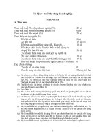
Interface between space segment and user equipment consists of radio links of L-band (see
Fig. 3.1). Each GLONASS satellite transmits navigation signals in two sub-bands of L-
band
(L1
1.6 GHz and L2
1.2 GHz).
GLONASS uses Frequency Division Multiple Access (FDMA) technique in both L1 and
L2 sub-bands. This means that each satellite transmits navigation signal on its own carrier
frequency in the L1 and L2 sub-bands. Two GLONASS satellites may transmit navigation signals
on the same carrier frequency if they are located in antipodal slots of a single orbital plane.
GLONASS satellites provide two types of navigation signals in the L1 and L2 sub-
bands:
standard accuracy signal and
high accuracy signal.
The standard accuracy signal with clock rate 0.511 MHz is designed for using by civil
users worldwide.
The high accuracy code with clock 5.11 MHz is modulated by special code, and its
unauthorized use (without permission of Ministry o
f Defence) is not recommended.
ICD provides structure and characteristics of the standard accuracy signal of both L1 and
L2
(1)
sub
-
bands.
The standard accuracy signal is available for any users equipped with proper receivers and
having visible GLONASS syst
em satellites above the horizon.
An intentional degradation of the standard accuracy signal is not applied.
Note (1): GLONASS-M satellites transmit in L1 sub-band signals at the same signals of
GLONASS satellites and provide users additional signals with the standard accuracy code in L2
sub
-band.
G LO NA S S S pa ce S eg m ent
L1, L2 sub-bands
C o n tro l
S eg m ent
R eceive r
O nboard
S oftware
S atellite
Figure 3.1 Satellite/Receiver Interface
Version 5.0 2002
GLONASS ICD
COORDINATION SCIENTIFIC INFORMATION CENTER
8
3.2 Navigation signal structure
Navigation signal being transmitted in particular carrier frequency of L1 and L2 sub-
bands
is a multi
-
component on
e using a bipolar phase
-
shift key (BPSK) modulated binary train. The phase
shift keying of the carrier is performed at
-
radians with the maximum error
0.2 radians.
The carrier of L1 sub
-
band is modulated by the Modulo
-
2 addition of the following binary
signals: pseudo random (PR) ranging code, digital data of navigation message and auxiliary
meander sequence.
The carrier of L2 sub-band is modulated by the Modulo-2 addition of the following binary
signals: PR ranging code and auxiliary meander sequence.
A
ll above
-
mentioned components are generated using a single onboard time/frequency
oscillator (standard).
3.2.1 Ranging code
PR ranging code is a sequence of the maximum length of a shift register (M-
sequence)
with a period 1 millisecond and bit rate 511 ki
lobits per second.
3.2.2 Digital data of navigation message
The navigation message includes immediate and non-
immediate data.
The immediate data relate to the satellite, which transmits given navigation signal. The
non-
immediate data (GLONASS almanac) rela
te to all satellites within GLONASS constellation.
The digital data are transmitted at 50 bits per second.
The content and the characteristics of the navigation message are given in
Section 4.
3.3 Interface description
3.3.1 Navigation RF signal character
istics
3.3.1.1 Frequency plan
The nominal values of L1 and L2 carrier frequencies are defined by the following
expressions:
f
K1
= f
01
+ K
f
1
,
f
K2
= f
02
+ K
f
2
,
where
K
is a frequency number (frequency channel) of the signals transmitted by GLONASS
s
atellites in the L1 and L2 sub
-bands correspondingly;
f
01
= 1602 MHz;
f
1
= 562.5 kHz,
for L1 sub
-
band;
f
02
= 1246 MHz;
f
2
= 437.5 kHz,
for L2 sub
-
band.
The nominal values of carrier frequencies f
K1
f
K2
for channel numbers K are given in
Table 3.1.
Channel number K for any particular GLONASS satellite is provided in almanac (non-
immediate data of navigation message, see paragraph 4.5).
For each satellite, carrier frequencies of L1 and L2 sub-
bands
are coherently derived from
a common onboard time/frequency standard. The nominal value of frequency, as observed on the
ground, is equal to 5.0 MHz. To compensate relativistic effects, the nominal value of the
frequency, as observed at satellite, is biased from 5.0 MHz by relative value f/f = -4.36 10
-
10
Version 5.0 2002
GLONASS ICD
COORDINATION SCIENTIFIC INFORMATION CENTER
9
or
f = -2.18 10
-3
Hz that is equal to 4.99999999782 MHz (the value is given for nominal orbital
height 19100 km). Ratio of carrier frequencies of L1 and L2 sub
-
bands is equal to
f
K2
/ f
K1
= 7/
9
The values of the carrier frequencies of the satellites are within 2 x 10
-
11
relative to its
nominal value f
k
.
Table 3.1
GLONASS carrier frequencies in L1 and L2 sub
-
bands
No. of
channel
Nominal value of frequency
in L1 sub
-
band, MHz
No. of
channel
No
minal value of frequency
in L2 sub
-
band, MHz
13 1609.3125 13 1251.6875
12 1608.75 12 1251.25
11 1608.1875 11 1250.8125
10 1607.625 10 1250.375
09 1607.0625 09 1249.9375
08 1606.5 08 1249.5
07 1605.9375 07 1249.0625
06 1605.375 06 1248.625
05 1604.8125 05 1248.1875
04 1604.25 04 1247.75
03 1603.6875 03 1247.3125
02 1603.125 02 1246.875
01 1602.5625 01 1246.4375
00 1602.0 00 1246.0
-01 1601.4375 -01 1245.5625
-02 1600.8750 -02 1245.1250
-03 1600.3125 -03 1244.6875
-04 1599.7500 -04 1244.2500
-05 1599.1875 -05 1243.8125
-06 1598.6250 -06 1243.3750
-07 1598.0625 -07 1242.9375
The following staged shift of the GLONASS frequency plan is stipulated:
1998
-
2005
At this stage GLONASS satellites will use frequency channels K = 0...12 without
any
restrictions. The channel numbers K = 0 and 13 will be used for technical purposes.
Version 5.0 2002
GLONASS ICD
COORDINATION SCIENTIFIC INFORMATION CENTER
10
Beyond 2005
At this stage GLONASS satellites will use frequency channels K = (
-
7...+6).
GLONASS satellites that are launched beyond 2005 will use filters, limiting out-
of
-
band
emissions to the harmful interference limit contained in CCIR Recommendation 769 for the (1610.6
... 1613.8) MHz and (1660 ... 1670) MHz bands.
3.3.1.2 Correlation loss
Correlation loss is defined as a difference between transmitted signal power i
n
(1598.0625 1605.375) MHz
0,511 MHz and (1242.9375 1248.625) MHz
0.511 MHz bands
and received signal power in ideal correlation-type receiver and in the same frequency bands. The
worst case of correlation loss occurs when receiving RF signal at channe
l number K = -
7 or K = 12.
For this case correlation loss is defined by the satellite modulation imperfections and are
-
0.6 dB.
For all other frequency channels the correlation loss, caused by waveform distortion, is
decreased as it moves away from edges
of the GLONASS L1 and L2 sub
-
bands.
3.3.1.3 Carrier phase noise
The phase noise spectral density of the non-modulated carrier is such that a phase locked
loop of 10 Hz one-sided noise bandwidth provides the accuracy of carrier phase tracking not worse
than
0.1 radian (1
).
3.3.1.4 Spurious emissions
Power of transmitted RF signal beyond of the following GLONASS allocated bandwidths
(1598.0625 1605.375) MHz
0.511 MHz,
(1242.9375 1248.625) MHz
0.511 MHz
(see paragraph 3.3.1.1) shall not be more than -40 dB relative to power of non-
modulated
carrier.
3.3.1.5 Intrasystem interference
Intrasystem interference caused by the inter-correlation properties of PR ranging code and
FDMA
technique utilized in GLONASS. When receiving navigation signal on frequency ch
annel
K = n, an interference created by navigation signal with frequency K = n-1 or K = n+1 is not more
than (-48 dB) provided that the satellites transmitting signals on adjacent frequencies are
simultaneously visible for an user.
3.3.1.6 Received power l
evel
The power level of the received RF signal from GLONASS satellite at the output of a 3dBi
linearly polarized antenna is not less than -161 dBW for L1 sub-band provided that the satellite is
observed at an angle of 5
or more.
The power level of the received RF signal from GLONASS-M satellite at the output of a
3dBi linearly polarized antenna is not less than -161 dBW for L1 sub-band and not less than -167
dBW (with the subsequent increasing to a level not less than -161 dBW) for L2 sub-band provided
tha
t the satellite is observed at an elevation angle of 5
or more.
Further information on received power level is given in Appendix 1.
Version 5.0 2002
GLONASS ICD
COORDINATION SCIENTIFIC INFORMATION CENTER
11
3.3.1.7 Equipment group delay
Equipment group delay is defined as a delay between transmitted RF signal (measured at
phas
e center of transmitting antenna) and a signal at the output of onboard time/frequency standard.
The delay consists of determined and undetermined components.
The determined component is no concern to an user since it has no effect on the
GLONASS time computations. The undetermined component does not exceed
8 nanoseconds for
GLONASS satellite and
2 nanoseconds for GLONASS
-
M satellite.
3.3.1.8 Signal coherence
All components of transmitted RF signal are coherently derived from carrier frequency of
only o
ne onboard time/frequency standard.
3.3.1.9 Polarization
Navigation RF signal transmitted in L1 and L2 sub-bands by each GLONASS satellite is
right
-
hand circularly polarized. The elliptic coefficient of the field is not worse than 0.7 (for both L1
and L2 sub
-bands) for the angular range 19
from boresight.
3.3.2 Modulation
The modulating sequence used for modulation of carrier frequencies sub-bands (when
generating standard accuracy signals) in L1 for GLONASS satellites and L1, L2 for GLONASS-
M
satellites
is generated by the Modulo
-
2 addition of the following three binary signals:
PR ranging code transmitted at 511 kbps;
navigation message transmitted at 50 bps, and
100 Hz auxiliary meander sequence.
Given sequences are used for modulation of carriers in L1 and L2 sub-bands when
generating standard accuracy signals.
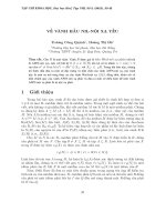
3.3.2.1 Ranging code generation
PR ranging code is a sequence of maximum length of shift register with a period 1
millisecond and bit rate 511 kbps.
PR ranging code is sampled at the output of 7
th
stage of the 9-stage shift register. The
initialization vector to generate this sequence is (111111111). The first character of the PR ranging
code is the first character in the group 111111100, and it is repeated every 1 millisecond. The
generating poly
nomial, which corresponds to the 9
-
stage shift register (see Fig. 3.2), is
G(X) = 1 + X
5
+ X
9
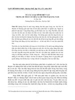
Simplified block-diagram of the PR ranging code and clock pulse generation is given in
Fig. 3.3.
Version 5.0 2002
GLONASS ICD
COORDINATION SCIENTIFIC INFORMATION CENTER
12
1
1
2
1
3
1
5
1
4
1
9
1
7
1
6
1
8
1
Input
register
cell
number
polinomial
G(
x)=1+x
5
+x
9
Direction
of
shift
local
output
Output
r
egister
cell
stat
us
0
1 2
3
4
5
6 7
8
9
Figure 3.2 Structure of shift regis
ter used for ranging code generation
to
processor
clock
pulses T=10
ms
set
all 1
reset
to 0
Shift
register
clock
pulses
f= 5
.
0
MHz
(
=200
ns)
:10 :10 :50
+
+
1 2 3 4 5 6 7 8 9
gate-pulses
Tc =1s
+
to
modulator
clock
pulses T=1s
Synchronization
trigger
from
onboard
frequency
standard
: 50 000
Synchronization
trigger
to
processor
f
T=
0.
511
MHz
Clock
pulses
generator
(
f = 5,0
MHz)
Reference
frequency 5.0
MHz
Figure 3.3 Simplified diagram of PR ranging code and clock pulse generation
Version 5.0 2002
GLONASS ICD
COORDINATION SCIENTIFIC INFORMATION CENTER
13
3.3.2.2 Navigation message generation
The navigation message is generated as a pattern of continuously repeating strings with
duration 2 seconds. During the first 1.7 seconds within this two
-
second interval (in the beginning of
each string) 85 bits of navigation data are transmitted. During the last 0.3 second within this two-
second interval (in the end of each stri
ng) the time mark is transmitted.
Binary train of the navigation message is Modulo-2 addition of the following binary
components:
a sequence of bits of the navigation message digital data in relative code and with
duration of one bit 20 milliseconds;
a mea
nder sequence with duration of one bit 10 millisecond.
The binary code of the time mark is a shortened pseudo random sequence of 30 bits, and
duration of one bit is equal to 10 milliseconds. This sequence is described by the following
generating polynomia
l:
g(x) = 1 + x
3
+ x
5
,
or may be shown as
111110001101110101000010010110.
The first bit of the digital data in each string is always 0 . It is idle character which
supplements shortened pseudo random sequence of the previous string time mark to the complete
(non
- shortened) one.
Simplified block-
diagram of the data sequence generation is given in Fig. 3.4
To modulator
PR ranging code
(T
c
2 s)
coder
one bit
delay
time mark
transformation into
relative code
(0.3 s )
(1.7 s )
meander:
d
1
... d
m
(T
c
= 10 ms)
data sequence
a
1
... a
K
(T
c
= 20 ms)
sequence of
data and checking bits
b
1
... b
n
(T
c
= 20 ms)
C
1
... C
n
(T
c
= 20 ms)
Figure 3.4 Simplified block
-
diagram of data sequence generation
Version 5.0 2002
GLONASS ICD
COORDINATION SCIENTIFIC INFORMATION CENTER
14
The boundaries of the two-second strings, data bits, meander bits, time mark bits and
ranging code bits are synchronized with each other within transmitted navigation signal. The
boundaries of the meander bits and the data bits coincide with leading edge of the ranging code
initial bit. The trailing edge of the latest bit of time mark corresponds to the moment that differs
from the beginning of the current day by integer and even number of seconds referring to the
satellite onboard time scale.
Time relationship between synchronizing pulses of the modulating binary train of the
navigation message and PR ranging code is given in Fig. 3.5. A process of the navigation message
generation is explained in Fig. 3.6. A content and a format of the navigation message are given in
Section 4 of the document
.
1s
10 m s
1 m s
P R rang in g cod e
(51 1 bits)
L =5 11 bits; T = 1 m s
=1.95 69 s
tim e
tim e
tim e
tim e
clo ck
pu lses
T =1 s
clo ck
pu lses
T =10 m s
clo ck
p ulses of
ra ng in g
co de
p erio d
1 1 1 1 1 1 1 1 1 1 1
111111 1
Figure 3.5 Time relationship between clock pulses and PR ranging code
even seconds in satellite onboard time scale
30 bits of tim e mark
85
data bits in bi-binary code
1.7 s 0.3 s
clock pulses (T =10 ms)
meander (T
c
=10 ms)
data bits (T
c
=20 ms) in relative code
data bits (T
c
=10 ms) in bi-binary code
time mark bits (T
c
=10 ms)
1 1111
1 1 1
1
1 1 1 1
1 1 1 1 1 1 1
1 1
0
0
0 0 0 0
0
0 0 0
0
0 0
0 0 0
Figure 3.6 Data sequence generation in onboard processor
Version 5.0 2002
GLONASS ICD
COORDINATION SCIENTIFIC INFORMATION CENTER
15
3.3.3 GLONASS time
The GLONASS satellites are equipped with clocks (time/frequency standards) which daily
instability is not worse than 5 10
-
13
and 1 10
-
13
for the GLONASS-M satellites. An accuracy of
mutual synchronization of the satellite time scales is not worse then 20 nanoseconds (1 ) for the
GLONASS and to 8 nanosec
onds (1
) for the GLONASS
-
M satellites.
GLONASS time is generated on a base of GLONASS Central Synchronizer (CS) time.
Daily instability of the Central Synchronizer hydrogen clocks in not worse
than 1
-5 10
-
14
.
Difference between GLONASS time and National Reference Time UTC(SU) shall be
within 1 millisecond. The navigation message contains the requisite data to relate GLONASS time
to UTS (SU) within 1 microsecond.
The time scales of the GLONASS satellites are periodically compared with the CS time
scale.
Corrections to each onboard time scale relative to GLONASS time and UTC (SU) (see
Section 4) are computed and uploaded to the satellites twice a day by control segment.
An accuracy of comparisons between onboard time scales and CS time does not exceed 10
nanoseconds at epoch of measurement.
The GLONASS time scale is periodically corrected to integer number of seconds
simultaneously with UTC corrections that are performed according to the Bureau International de
l Heure (BIH) notification (leap second correction). Typically, these corrections ( 1s) are
performed once a year (or 1.5 years) at midnight 00 hours 00 minutes 00 seconds UTC from
December 31 to January 1
1-st quarter (or from March 31 to April 1
2-nd quarter or from June
30 to July 1 3
-
rd quar
ter or from September 30 to October 1
- 4-
th quarter) by all UTC users.
GLONASS users are notified in advance (at least three months before) on these planned
corrections through relevant bulletins, notifications etc. The GLONASS satellites have not any da
ta
concerning the UTC leap second correction within their navigation messages.
During the leap second correction, GLONASS time is also corrected by changing
enumeration of second pulses of onboard clocks of all GLONASS satellites. Here the time mark
within
navigation message changes its position (in a continuous time scale) to become synchronized
with two
-
second epochs of corrected UTC time scale. This change occurs at 00 hours 00 minutes 00
seconds UTC. Navigation message of GLONASS-M satellites stipulates provision of advance
notice for users on forthcoming UTC leap second correction, its value and sign (see Section 4.5,
word KP within almanac).
General recommendations concerning operation of GLONASS receiver upon the UTC leap
second correction are given i
n Appendix 2
.
Due to the leap second correction there is no integer-second difference between
GLONASS time and UTC (SU). However, there is constant three-hour difference between these
time scales due to GLONASS control segment specific features:
t
GLONASS
= UTC(SU) + 03 hours 00 minutes
To re-compute satellite ephemeris at a moment of measurements in UTC(SU) the
following equation shall be used:
t
UTC(SU)
+ 03 hours 00 minutes = t +
c
+
n
( t
b
)
-
n
(t
b
) (t
-
t
b
), where
t
time of transmission of navigation signal in onboard time scale (parameters
c
,
n
,
n
,
and t
b
are given in Sections 4.4 and 4.5).
GLONASS
-
M satellite transmitted coefficients B1 and B2 to determine the difference between
Universal Time UT1 and Universal Coordinated Time UTC.
GLONASS
-
M
satellite transmitted
GPS
- correction to GPS time relative to GLONASS
Version 5.0 2002
GLONASS ICD
COORDINATION SCIENTIFIC INFORMATION CENTER
16
time (or difference between these time scales) which shall be
not more 30 ns (
).
3.3.4 Coordinate system
The GLONASS broadcast ephemeris describes a position of transmitting antenna phase
center of given satellite in the PZ-90 Earth-Centered Earth-Fixed reference frame defined as
follows:
The ORIGIN is located at the center of the Earth's body;
The Z
-
axis is directed to the Conventional Terrestrial Pole
as recommended by the
International Earth Rotation Service (IERS);
The X
-
axis is directed to the point of intersection of the Earth's equatorial plane and the
zero meridian established by BIH;
The Y
-
axis completes the coordinate sys
tem to the right
-
handed one.
Geodetic coordinates of a point in the PZ-90 coordinate system refers to the ellipsoid
which semi
-
major axis and flattening are given in Table 3.2
Geodetic latitude B of a point M is defined as angle between the normal to the
ellipsoid
surface and equatorial plane.
Geodetic longitude L of a point M is defined as angle between plane of the initial (zero)
meridian and plane of a meridian passing through the point M. Positive direction of the longitude
count from the initial merid
ian to east.
Geodetic height H of a point M is defined as a distance from the ellipsoid surface to the
point M along the normal.
Fundamental geodetic constants and other significant parameters of the common terrestrial
ellipsoid PZ
-
90 are given in Table 3.2.
Table 3.2 Geodetic constants and parameters of PZ
-90 common terrestrial ellipsoid
Earth rotation rate
7.292115x10
-5
radian/s
Gravitational constant
398 600.44x10
9
m
3
/s
2
Gravitational constant of atmosphere(
fM
a
)
0.35x10
9
m
3
/s
2
Speed of light
299 792 458 m/s
Semi
-
major axis
6 378 136 m
Flattening
1/298.257 839 303
Equatorial acceleration of gravity
978 032.8 mgal
Correction to acceleration of gravity at sea
-
level due to
Atmosphere
-
0.9 mgal
Second zonal harmonic of the geopotential (J
2
0
) 1082625.7x10
-9
Fourth zonal harmonic of the geopotential (
J
4
0
)
(-
2370.9x10
-9
)
Normal potential at surface of common terrestrial ellipsoid (
U
0
)
62 636 861.074 M
2
/s
2
Version 5.0 2002
GLONASS ICD
COORDINATION SCIENTIFIC INFORMATION CENTER
17
Note.
To calculate of orbit parameters same times can be used next normalized
harmo
nic of the
normal geopotential (PZ
-
90):
_ _
C
20
0
=
-
484165,0x10
-9
; C
40
0
= 790,3x10
-9
.
Conection between this paramters and ICD paramte
rs are:
_ _
J
2
0
=
-
(5)
1/2
C
20
0
= 1082625,7x10
-9
; (J
4
0
) =
-
3 C
40
0
=
-
2370,9x10
-9
Conection between paramters
normal and unnormal geopotential are:
_ _ _ _ _ _
C
20
= C
20
-
C
20
0
= 0
C
40
= C
40
-
C
40
0
=
-
246,8x10
-9
Version 5.0 2002
GLONASS ICD
COORDINATION SCIENTIFIC INFORMATION CENTER
18
4. NAVIGATION MESSAGE
A content and a format of the GLONASS and GLONASS
-
M satellites nav
igation message
are given in this Section.
4.1 Navigation message purpose
The navigation message transmitted by the GLONASS and GLONASS-M satellites
satellites within navigation signal is purposed to provide users with requisite data for positioning,
timin
g and planning observations.
4.2 Navigation message content
The navigation message includes immediate data and non
-
immediate data.
The immediate data relate to the GLONASS satellite which broadcasts given RF
navigation signal and include:
enumeration of th
e satellite time marks;
difference between onboard time scale of the satellite and GLONASS time;
relative difference between carrier frequency of the satellite and its nominal value;
ephemeris parameters and the other parameters (see section 4.4).
The non-immediate data contain almanac of the system including:
data on status of all satellites within space segment (status almanac);
coarse corrections to onboard time scale of each satellite relative to GLONASS time
(phase almanac);
orbital parameters
of all satellites within space segment (orbit almanac);
correction to GLONASS time relative to UTC(SU) and the other parameters (see
section 4.5).
4.3 Navigation message structure
The navigation message is transmitted as a pattern of digital data that are coded by
Hamming code and transformed into relative code. Structurally the data pattern is generated as
continuously repeating superframes. A superframe consists of the frames, and a frame consists of
the strings.
The boundaries of strings, frames and superframes of navigation messages from different
GLONASS satellites are synchronized within 2 milliseconds.
4.3.1 Superframe structure
The superframe has duration 2.5 minutes and consists of 5 frames. Each frame has duration
30 seconds and consists of 15 str
ings. Each string has duration 2 seconds.
Within each frame a total content of non-immediate data (almanac for 24 GLONASS
system satellites) are transmitted.
Superframe structure with indication of frame numbers in the superframe and string
numbers in the
frames is given in Fig. 4.1.
Version 5.0 2002
GLONASS ICD
COORDINATION SCIENTIFIC INFORMATION CENTER
19
3
0
s
5
=
2
.
5
m
i
n
u
t
e
s
30 s
Frame number String number
1 0 Immediate data
2 0 for
3 0 transmitting
I 4 0 satellite
. Non-immediate data
. (almanac)for
15
0 five satellites
1 0 Immediate data
2 0 for
3 0 transmitting
II
4 0 satellite
. Non-immediate data
. (almanac)for
15
0 five satellites
1 0 Immediate data
2 0 for
3 0 transmitting
III
4 0 satellite
. Non-immediate data
. (almanac)for
15
0 five satellites
1 0 Immediate data
2 0 for
3 0 transmitting
IV
4 0 satellite
. Non-immediate data
. (almanac)for
15
0 five satellites
1 0 Immediate data
2 0 for
3 0 transmitting
4 0 satellite
V .
.
Non-immediate data
(almanac) for four satellites
14
0 Reserved bits
15
0 Reserved bits
1.7 s 0.3 s
2 s
Hamming code
bits
in relative
bi-binary code
data bits
in relative
bi-binary code
bit number
within
string
85
84
............. .......
9 8
......
...
1
Figure 4.1 Superframe structure
Version 5.0 2002
GLONASS ICD
COORDINATION SCIENTIFIC INFORMATION CENTER
20
4.3.2 Frame structure
The superframe has duration 2.5 minutes and consists of 5 frames. Each frame has duration
30 seconds and consists of 15 strings. Each string h
as duration 2 seconds.
Within each frame the total content of immediate data for given satellite and a part of non-
immediate data are transmitted.
Frame structure within superframe is given in Fig. 4.2.
The frames 1 4 are identical. Shaded area in Fig. 4.2 indicates reserved bits are to be
utilized in future modernization of the navigation message structure.
The data contained in strings 1 4 of each frame relate to the satellite that transmits given
navigation message (immediate data). The immediate data ar
e the same within one superframe.
The strings 6 15 of each frame contain non-immediate data (almanac) for 24 satellites.
The frames 1 4 contain almanac for 20 satellites (5 satellites per frame). The 5
th
frame contains
remainder of almanac for 4 satellites. Non-immediate data (almanac) for one satellite occupy two
strings. Data contained in 5
th
string of each frame are the same within one superframe and relate to
non-
immediate data.
Arrangement of almanac within superframe is given in Table 4.1.
Table 4.1
Arrangement of GLONASS almanac within superframe
Frame number within superframe
Satellite numbers, for which almanac is
transmitted within given superframe
1 1 5
2 6 10
3 11 15
4 16 20
5 21 - 24
Version 5.0 2002
GLONASS ICD
COORDINATION SCIENTIFIC INFORMATION CENTER
21
GPS
b
n
2
N
m
4
c
KX
MB
32
22
8
11
l
n
A
n
n
m
4
A
n
KX
MB
10
15
8
5
A
n
21
18
i
A
n
n
m
4
KX
MB
7
8
16
A
n
21
22
T
A
n
T
A
n
l
n
A
n
5
A
n
n
m
4
A
n
KX
MB
10
15
8
5
A
n
21
18
i
A
n
n
m
4
KX
MB
7
8
16
A
n
21
22
T
A
n
T
A
n
l
n
A
n
5
A
n
n
m
4
A
n
KX
MB
10
15
8
5
A
n
21
18
i
A
n
n
m
4
KX
MB
7
8
16
A
n
21
22
T
A
n
T
A
n
l
n
A
n
5
A
n
n
m
4
A
n
KX
MB
10
15
8
5
A
n
21
18
i
A
n
n
m
4
KX
MB
7
8
16
A
n
21
22
T
A
n
T
A
n
l
n
A
n
5
A
n
n
m
4
A
n
KX
MB
10
15
8
5
A
n
21
18
i
A
n
n
m
4
KX
MB
7
8
16
A
n
21
22
T
A
n
T
A
n
l
n
A
n
5
1
2
3
4
5
6
7
8
9
10
11
12
13
14
15
M
n
a
2
M
n
a
2
M
n
a
2
M
n
a
2
M
n
a
2
(C
n
1
)
c
n
7
t
b
B
n
m
4
y
n
(t
b
)
y
n
(t
b
)
y
n
(t
b
)
KX
MB
24
5
27
8
p
m
4
P1
t
k
x
n
(t
b
)
x
n
(t
b
)
x
n
(t
b
)
KX
MB
12
24
5
27 8
m
4
n
(t
b
)
z
n
(t
b
)
z
n
(t
b
)
z
n
(t
b
)
KX
MB
11
24
5
27
8
m
4
n
(t
b
)
E
n
KX
MB
22
5
8
l
n
string
P4
(P
3
1
)
(P2
1
)
2
N
T
11
F
4
n
5
2
2
53
1
2
1
5
n
3
1
14
1
N
4
5
Figure 4.2a Frame
structure, 1
st
4
th
frames
GPS
b
n
2
N
m
4
c
KX
MB
32
22
8
11
l
n
A
n
n
m
4
A
n
KX
MB
10
15
8
5
A
n
21
18
i
A
n
n
m
4
KX
MB
7
8
16
A
n
21
22
T
A
n
T
A
n
l
n
A
n
5
A
n
n
m
4
A
n
KX
MB
10
15
8
5
A
n
21
18
i
A
n
n
m
4
KX
MB
7
8
16
A
n
21
22
T
A
n
T
A
n
l
n
A
n
5
A
n
n
m
4
A
n
KX
MB
10
15
8
5
A
n
21
18
i
A
n
n
m
4
KX
MB
7
8
16
A
n
21
22
T
A
n
T
A
n
l
n
A
n
5
A
n
n
m
4
A
n
KX
MB
10
15
8
5
A
n
21
18
i
A
n
n
m
4
KX
MB
7
8
16
A
n
21
22
T
A
n
T
A
n
l
n
A
n
5
1
2
3
4
5
6
7
8
9
10
11
12
13
14
15
M
n
a
2
M
n
a
2
M
n
a
2
M
n
a
2
(C
n
1
)
c
n
7
t
b
B
n
m
4
y
n
(t
b
)
y
n
(t
b
)
y
n
(t
b
)
KX
MB
24
5
27
8
p
m
4
P1
t
k
x
n
(t
b
)
x
n
(t
b
)
x
n
(t
b
)
KX
MB
12
24
5
27
8
m
4
n
(t
b
)
z
n
(t
b
)
z
n
(t
b
)
z
n
(t
b
)
KX
MB
11
24
5
27
8
m
4
n
(t
b
)
E
n
KX
MB
22
5
8
l
n
string
P4
(P3
1
)
(P2
1
)
2
N
T
11
F
4
n
5
2
2
53
1
2
2
5
n
3
1
14
1
N
4
5
1
m
4
2
KX
MB
10
8
11
2
m
4
KX
MB
8
l
n
Figure. 4.2b Frame structure, 5
th
frame
Version 5.0 2002
GLONASS ICD
COORDINATION SCIENTIFIC INFORMATION CENTER
22
4.3.3 String structure
String is a structural element of the frame. String structure is given in Fig. 4.3. Each string
contains data bits and time mark. String has duration 2 seconds, and during the last 0.3 seconds
within this two-second interval (in the end of each string) the time mark is transmitted. The time
mark (shortened pseudo random sequence) consists of 30 chips. Duration of the chip is 10
millisecon
ds (see paragraph 3.3.2.2). During the first 1.7 seconds within this two
-
second interval (in
the beginning of each string) 85 bits of data are transmitted (the Modulo-2 addition of 50 Hz
navigation data and 100 Hz auxiliary meander sequence (bi
-
binary code
)).
The numbers of bits in the string are increased from right to the left. Along with data bits
(bit positions 9 84) the check bits of Hamming code (KX) (bit positions 1 8) are transmitted.
The Hamming code has a code length of 4. The data of one string are separated from the data of
adjacent strings by time mark (MB). The words of the data are registered by most significant bit
(MSB) ahead. The last bit in each string (bit position 85) is idle chip ("0"). It serves for realization
of sequential relative c
ode when transmitting the navigation data via radio link.
0.
3
s
2.
0
s
1.
7
s
Data bits and check bits in
bi-binary code
(
Tc
=
10
ms
)
Time mark
(
Tc
=
10
ms
)
1111100 ... 110
Bit numbers
within string
Data bits in relative
bi-binary code
Hamming code bits
(
1-8)
in relative
bi-binary
code
85
9 8
2 1
Figure 4.3 String structure
4.4 Immediate information and ephemeris parameters
Characteristics of words of immediate information (ephemeris parameters) are given in
Table 4.
5. In the words which numerical values may be positive or negative, the MSB is the sign
bit. The chip "0" corresponds to the sign "+", and the chip "1" corresponds to the sign "-
".
Ephemeris parameters are periodically computed and uploaded to the satellites by control
segment.
Mean square errors of transmited coordinates and velocities of the satellites are given in
Table 4.2.