Sổ tay kết cấu thép - Section 5
Bạn đang xem bản rút gọn của tài liệu. Xem và tải ngay bản đầy đủ của tài liệu tại đây (768.25 KB, 109 trang )
5.1
SECTION 5
CONNECTIONS
W. A. Thornton, P.E.
Chief Engineer, Cives Steel Company, Roswell, Ga.
T. Kane, P.E.
Technical Manager, Cives Steel Company, Roswell, Ga.
In this section, the term connections is used in a general sense to include all types of joints
in structural steel made with fasteners or welds. Emphasis, however, is placed on the more
commonly used connections, such as beam-column connections, main-member splices, and
truss connections.
Recommendations apply to buildings and to both highway and railway bridges unless
otherwise noted. This material is based on the specifications of the American Institute of
Steel Construction (AISC), ‘‘Load and Resistance Factor Design Specification for Structural
Steel Buildings,’’ 1999, and ‘‘Specification for Structural Steel Buildings—Allowable Stress
Design and Plastic Design,’’ 1989; the American Association of State Highway and Trans-
portation Officials (AASHTO), ‘‘Standard Specifications for Highway Bridges,’’ 1996; and
the American Railway Engineering and Maintenance-of-Way Association (AREMA), ‘‘Man-
ual,’’ 1998.
5.1 LIMITATIONS ON USE OF FASTENERS AND WELDS
Structural steel fabricators prefer that job specifications state that ‘‘shop connections shall
be made with bolts or welds’’ rather than restricting the type of connection that can be used.
This allows the fabricator to make the best use of available equipment and to offer a more
competitive price. For bridges, however, standard specifications restrict fastener choice.
High-strength bolts may be used in either slip-critical or bearing-type connections (Art.
5.3), subject to various limitations. Bearing-type connections have higher allowable loads
and should be used where permitted. Also, bearing-type connections may be either fully
tensioned or snug-tight, subject to various limitations. Snug-tight bolts are much more eco-
nomical to install and should be used where permitted.
Bolted slip-critical connections must be used for bridges where stress reversal may occur
or slippage is undesirable. In bridges, connections subject to computed tension or combined
shear and computed tension must be slip-critical. Bridge construction requires that bearing-
type connections with high-strength bolts be limited to members in compression and sec-
ondary members.
Carbon-steel bolts should not be used in connections subject to fatigue.
5.2
SECTION FIVE
In building construction, snug-tight bearing-type connections can be used for most cases,
including connections subject to stress reversal due to wind or low seismic loading. The
American Institute of Steel Construction (AISC) requires that fully tensioned high-strength
bolts or welds be used for connections indicated in Sec. 6.14.2.
The AISC imposes special requirements on use of welded splices and similar connections
in heavy sections. This includes ASTM A6 group 4 and 5 shapes and splices in built-up
members with plates over 2 in thick subject to tensile stresses due to tension or flexure.
Charpy V-notch tests are required, as well as special fabrication and inspection procedures.
Where feasible, bolted connections are preferred to welded connections for such sections
(see Art. 1.17).
In highway bridges, fasteners or welds may be used in field connections wherever they
would be permitted in shop connections. In railroad bridges, the American Railway Engi-
neering Association (AREA) recommended practice requires that field connections be made
with high-strength bolts. Welding may be used only for minor connections that are not
stressed by live loads and for joining deck plates or other components that are not part of
the load-carrying structure.
5.2 BOLTS IN COMBINATION WITH WELDS
In new work, ASTM A307 bolts or high-strength bolts used in bearing-type connections
should not be considered as sharing the stress in combination with welds. Welds, if used,
should be provided to carry the entire stress in the connection. High-strength bolts propor-
tioned for slip-critical connections may be considered as sharing the stress with welds.
In welded alterations to structures, existing rivets and high-strength bolts tightened to the
requirements for slip-critical connections are permitted for carrying stresses resulting from
loads present at the time of alteration. The welding needs to be adequate to carry only the
additional stress.
If two or more of the general types of welds (groove. fillet, plug, slot) are combined in
a single joint, the effective capacity of each should be separately computed with reference
to the axis of the group in order to determine the allowable capacity of the combination.
AREMA does not permit the use of plug or slot welds but will accept fillet welds in
holes and slots.
FASTENERS
In steel erection, fasteners commonly used include bolts, welded studs, and pins. Properties
of these are discussed in the following articles.
5.3 HIGH-STRENGTH BOLTS, NUTS, AND WASHERS
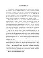
For general purposes, A325 and A490 high-strength bolts may be specified. Each type of
bolt can be identified by the ASTM designation and the manufacturer’s mark on the bolt
head and nut (Fig. 5.1). The cost of A490 bolts is 15 to 20% greater than that of A325
bolts.
Job specifications often require that ‘‘main connections shall be made with bolts con-
forming to the Specification for Structural Joints Using ASTM A325 and A490 Bolts.’’ This
CONNECTIONS
5.3
FIGURE 5.1 A325 high-strength structural steel bolt with heavy hex nut; heads are also marked
to identify the manufacturer or distributor. Type 1 A325 bolts may additionally be marked with
three radial lines 120
Њ
apart. Type 3 (weathering steel) bolts are marked as A325 and may also
have other distinguishing marks to indicate a weathering grade.
TABLE 5.1
Thread Lengths for High-Strength Bolts
Bolt diamter, in Nominal thread, in Vanish thread, in Total thread, in
1
⁄
2
1.00 0.19 1.19
5
⁄
8
1.25 0.22 1.47
3
⁄
4
1.38 0.25 1.63
7
⁄
8
1.50 0.28 1.78
1 1.75 0.31 2.06
1
1
⁄
8
2.00 0.34 2.34
1
1
⁄
4
2.00 0.38 2.38
1
3
⁄
8
2.25 0.44 2.69
1
1
⁄
2
2.25 0.44 2.69
specification, approved by the Research Council on Structural Connections (RCSC) of the
Engineering Foundation, establishes bolt, nut, and washer dimensions, minimum fastener
tension, and requirements for design and installation.
As indicated in Table 5.1, many sizes of high-strength bolts are available. Most standard
connection tables, however, apply primarily to
3
⁄
4
-and
7
⁄
8
-in bolts. Shop and erection equip-
ment is generally set up for these sizes, and workers are familiar with them.
Bearing versus Slip-Critical Joints. Connections made with high-strength bolts may be
slip-critical (material joined being clamped together by the tension induced in the bolts by
tightening them) or bearing-type (material joined being restricted from moving primarily by
the bolt shank). In bearing-type connections, bolt threads may be included in or excluded
from the shear plane. Different stresses are allowed for each condition. The slip-critical
connection is the most expensive, because it requires that the faying surfaces be free of paint
(some exceptions are permitted), grease, and oil. Hence this type of connection should be
used only where required by the governing design specification, e.g., where it is undesirable
to have the bolts slip into bearing or where stress reversal could cause slippage (Art. 5.1).
Slip-critical connections, however, have the advantage in building construction that when
used in combination with welds, the fasteners and welds may be considered to share the
stress (Art. 5.2). Another advantage that sometimes may be useful is that the strength of
slip-critical connections is not affected by bearing limitations, as are other types of fasteners.
5.4
SECTION FIVE
TABLE 5.2
Lengths to be Added to Grip
Nominal bolt size, in
Addition to grip for
determination of bolt length, in
1
⁄
2
11
⁄
16
5
⁄
8
7
⁄
8
3
⁄
4
1
7
⁄
8
1
1
⁄
8
11
1
⁄
4
1
1
⁄
8
1
1
⁄
2
1
1
⁄
4
1
5
⁄
8
1
3
⁄
8
1
3
⁄
4
1
1
⁄
2
1
7
⁄
8
Threads in Shear Planes. The bearing-type connection with threads in shear planes is
frequently used. Since location of threads is not restricted, bolts can be inserted from either
side of a connection. Either the head or the nut can be the element turned. Paint is permitted
on the faying surfaces.
Threads Excluded from Shear Planes. The bearing-type connection with threads excluded
from shear planes is the most economical high-strength bolted connection, because fewer
bolts generally are needed for a given capacity. But this type should be used only after
careful consideration of the difficulties involved in excluding the threads from the shear
planes. The location of the thread runout depends on which side of the connection the bolt
is entered and whether a washer is placed under the head or the nut. This location is difficult
to control in the shop but even more so in the field. The difficulty is increased by the fact
that much of the published information on bolt characteristics does not agree with the basic
specification used by bolt manufacturers (American National Standards Institute B18.2.1).
Thread Length and Bolt Length. Total nominal thread lengths and vanish thread lengths
for high-strength bolts are given in Table 5.1. It is common practice to allow the last
1
⁄
8
in
of vanish thread to extend across a single shear plane. In order to determine the required
bolt length, the value shown in Table 5.2 should be added to the grip (i.e., the total thickness
of all connected material, exclusive of washers). For each hardened flat washer that is used,
add
5
⁄
32
in, and for each beveled washer, add
5
⁄
16
in. The tabulated values provide appropriate
allowances for manufacturing tolerances and also provide for full thread engagement with
an installed heavy hex nut. The length determined by the use of Table 5.2 should be adjusted
to the next longer
1
⁄
4
-in length.
Washer Requirements. The RCSC specification requires that design details provide for
washers in connections with high-strength bolts as follows:
1. A hardened beveled washer should be used to compensate for the lack of parallelism
where the outer face of the bolted parts has a greater slope than 1:20 with respect to a
plane normal to the bolt axis.
2. For A325 and A490 bolts for slip-critical connections and connections subject to direct
tension, hardened washers are required as specified in items 3 through 7 below. For bolts
permitted to be tightened only snug-tight, if a slotted hole occurs in an outer ply, a flat
hardened washer or common plate washer shall be installed over the slot. For other
connections with A325 and A490 bolts, hardened washers are not generally required.
CONNECTIONS
5.5
3. When the calibrated wrench method is used for tightening the bolts, hardened washers
shall be used under the element turned by the wrench.
4. For A490 bolts tensioned to the specified tension, hardened washers shall be used under
the head and nut in steel with a specified yield point less than 40 ksi.
5. A hardened washer conforming to ASTM F436 shall be used for A325 or A490 bolts 1
in or less in diameter tightened in an oversized or short slotted hole in an outer ply.
6. Hardened washers conforming to F436 but at least
5
⁄
16
in thick shall be used, instead of
washers of standard thickness, under both the head and nut of A490 bolts more than 1
in in diameter tightened in oversized or short slotted holes in an outer ply. This require-
ment is not met by multiple washers even though the combined thickness equals or
exceeds
5
⁄
16
in.
7. A plate washer or continuous bar of structural-grade steel, but not necessarily hardened,
at least
5
⁄
16
in thick and with standard holes, shall be used for an A325 or A490 bolt 1
in or less in diameter when it is tightened in a long slotted hole in an outer ply. The
washer or bar shall be large enough to cover the slot completely after installation of the
tightened bolt. For an A490 bolt more than 1 in in diameter in a long slotted hole in an
outer ply, a single hardened washer (not multiple washers) conforming to F436, but at
least
5
⁄
16
in thick, shall be used instead of a washer or bar of structural-grade steel.
The requirements for washers specified in items 4 and 5 above are satisfied by other types
of fasteners meeting the requirements of A325 or A490 and with a geometry that provides
a bearing circle on the head or nut with a diameter at least equal to that of hardened F436
washers. Such fasteners include ‘‘twist-off’’ bolts with a splined end that extends beyond the
threaded portion of the bolt. During installation, this end is gripped by a special wrench
chuck and is sheared off when the specified bolt tension is achieved.
The RCSC specification permits direct tension-indicating devices, such as washers incor-
porating small, formed arches designed to deform in a controlled manner when subjected to
the tightening force. The specification also provides guidance on use of such devices to
assure proper installation (Art. 5.14).
5.4 CARBON-STEEL OR UNFINISHED (MACHINE) BOLTS
‘‘Secondary connections may be made with unfinished bolts conforming to the Specifications
for Low-carbon Steel ASTM A307’’ is an often-used specification. (Unfinished bolts also
may be referred to as machine, common, or ordinary bolts.) When this specification is
used, secondary connections should be carefully defined to preclude selection by ironworkers
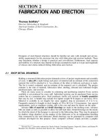
of the wrong type of bolt for a connection (see also Art. 5.1). A307 bolts have identification
marks on their square, hexagonal, or countersunk heads (Fig. 5.2), as do high-strength bolts.
Use of high-strength bolts where A307 bolts provide the required strength merely adds
to the cost of a structure. High-strength bolts cost at least 10% more than machine bolts.
A disadvantage of A307 bolts is the possibility that the nuts may loosen. This may be
eliminated by use of lock washers. Alternatively, locknuts can be used or threads can be
jammed, but either is more expensive than lock washers.
5.5 WELDED STUDS
Fasteners with one end welded to a steel member frequently are used for connecting material.
Shear connectors in composite construction are a common application. Welded studs also
5.6
SECTION FIVE
FIGURE 5.2 A307 Grade A carbon-steel bolts; heads are also marked to identify the manufac-
turer or distributor. (a) With hexagonal nut and bolt. (b) With square head and nut. (c) With
countersunk head.
TABLE 5.3
Allowable Loads (kips) on
Threaded Welded Studs
(ASTM A108, grade 1015, 1018, or 1020)
Stud size, in Tension Single shear
5
⁄
8
6.9 4.1
3
⁄
4
10.0 6.0
7
⁄
8
13.9 8.3
1 18.2 10.9
are used as anchors to attach wood, masonry, or concrete to steel. Types of studs and welding
guns vary with manufacturers.
Table 5.3 lists approximate allowable loads for Allowable Stress Design for several sizes
of threaded studs. Check manufacturer’s data for studs to be used. Chemical composition
and physical properties may differ from those assumed for this table.
Use of threaded studs for steel-to-steel connections can cut costs. For example, fastening
rail clips to crane girders with studs eliminates drilling of the top flange of the girders and
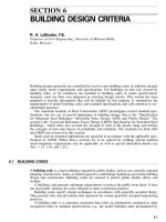
may permit a reduction in flange size. In designs with threaded studs, clearance must be
provided for stud welds. Usual sizes of these welds are indicated in Fig. 5.3 and Table 5.4.
The dimension C given is the minimum required to prevent burn-through in stud welding.
Other design considerations may require greater thicknesses.
CONNECTIONS
5.7
FIGURE 5.3 Welded stud.
TABLE 5.4
Minimum Weld and
Base-Metal Dimensions (in) for
Threaded Welded Studs
Stud size, in ABand C
5
⁄
8
1
⁄
8
1
⁄
4
3
⁄
4
3
⁄
16
5
⁄
16
7
⁄
8
3
⁄
16
3
⁄
8
1
1
⁄
4
7
⁄
16
5.6 PINS
A pinned connection is used to permit rotation of the end of a connected member. Some
aspects of the design of a pinned connection are the same as those of a bolted bearing
connection. The pin serves the same purpose as the shank of a bolt. But since only one pin
is present in a connection, forces acting on a pin are generally much greater than those on
a bolt. Shear on a pin can be resisted by selecting a large enough pin diameter and an
appropriate grade of steel. Bearing on thin webs or plates can be brought within allowable
values by addition of reinforcing plates. Because a pin is relatively long, bending, ignored
in bolts, must be investigated in choosing a pin diameter. Arrangements of plates on the pin
affect bending stresses. Hence plates should be symmetrically placed and positioned to min-
imize stresses.
Finishing of the pin and its effect on bearing should be considered. Unless the pin is
machined, the roundness tolerance may not permit full bearing, and a close fit of the pin
may not be possible. The requirements of the pin should be taken into account before a fit
is specified.
Pins may be made of any of the structural steels permitted by AISC, AASHTO, and
AREA specifications, ASTM A108 grades 1016 through 1030, and A668 classes C, D, F,
and G.
Pins must be forged and annealed when they are more than 7 in in diameter for railroad
bridges. Smaller pins may be forged and annealed or cold-finished carbon-steel shafting. In
pins larger than 9 in in diameter, a hole at least 2 in in diameter must be bored full length
along the axis. This work should be done after the forging has been allowed to cool to a
temperature below the critical range, with precautions taken to prevent injury by too rapid
cooling, and before the metal is annealed. The hole permits passage of a bolt with threaded
ends for attachment of nuts or caps at the pin ends.
When reinforcing plates are needed on connected material, the plates should be arranged
to reduce eccentricity on the pin to a minimum. One plate on each side should be as wide
as the outstanding flanges will permit. At least one full-width plate on each segment should
5.8
SECTION FIVE
FIGURE 5.4 Pins. (a) With recessed nuts. (b) With caps and through bolt. (c) With
forged head and cotter pin. (d) With cotter at each end (used in horizontal position).
extend to the far end of the stay plate. Other reinforcing plates should extend at least 6 in
beyond the near edge. All plates should be connected with fasteners or welds arranged to
transmit the bearing pressure uniformly over the full section.
In buildings, pinhole diameters should not exceed pin diameters by more than
1
⁄
32
in. In
bridges, this requirement holds for pins more than 5 in in diameter, but for smaller pins, the
tolerance is reduced to
1
⁄
50
in.
Length of pin should be sufficient to secure full bearing on the turned body of the pin
of all connected parts. Pins should be secured in position and connected material restrained
against lateral movement on the pins. For the purpose, ends of a pin may be threaded, and
hexagonal recessed nuts or hexagonal solid nuts with washers may be screwed on them (Fig.
5.4a). Usually made of malleable castings or steel, the nuts should be secured by cotter pins
in the screw ends or by burred threads. Bored pins may be held by a recessed cap at each
end, secured by a nut on a bolt passing through the caps and the pin (Fig. 5.4b). In building
work, a pin may be secured with cotter pins (Fig. 5.4c and d ).
The most economical method is to drill a hole in each end for cotter pins. This, however,
can be used only for horizontal pins. When a round must be turned down to obtain the
required fit, a head can be formed to hold the pin at one end. The other end can be held by
a cotter pin or threaded for a nut.
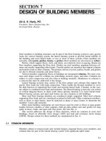
Example. Determine the diameter of pin required to carry a 320-kip reaction of a deck-
truss highway bridge (Fig. 5.5) using Allowable Stress Design (ASD).
Bearing. For A36 steel, American Association of State Highway and Transportation
Officials (AASHTO) specifications permit a bearing stress of 14 ksi on pins subject to ro-
tation, such as those used in rockers and hinges. Hence the minimum bearing area on the
pin must equal
2
320
A
ϭ
⁄
14
ϭ
22.8 in
Assume a 6-in-diameter pin. The bearing areas provided (Fig. 5.5) are
CONNECTIONS
5.9
FIGURE 5.5 Pinned bearing for deck-truss highway bridge.
5.10
SECTION FIVE
Flanges of W12
ϫ
65 2
ϫ
6
ϫ
0.605
ϭ
7.26
3
Fill plates 2
ϫ
6
ϫ
⁄
8
ϭ
4.50
5
Gusset plates 2
ϫ
6
ϫ
⁄
8
ϭ
7.50
3
Pin plates 2
ϫ
6
ϫ
⁄
8
ϭ
4.50
2
23.76 in
Ͼ
22.8
2
Bearing plates 2
ϫ
6
ϫ
2
ϭ
24.00 in
Ͼ
22.8
The 6-in pin is adequate for bearing.
Shear. For A36 steel, AASHTO specifications permit a shear stress on pins of 14 ksi.
As indicated in the loading diagram for the pin in Fig. 5.5, the reaction is applied to the pin
at two points. Hence the shearing area equals 2
ϫ
(6)
2
/4
ϭ
56.6. Thus the shearing stress
is
320
ƒ
ϭϭ
5.65 ksi
Ͻ
14
v
56.6
The 6-in pin is adequate for shear.
Bending. For A36 steel, consider an allowable bending stress of 20 ksi. From the loading
diagram for the pin (Fig. 5.5), the maximum bending moment is M
ϭ
160
ϫ
2
1
⁄
8
ϭ
340 in-
kips. The section modulus of the pin is
33
d
(6)
3
S
ϭϭ ϭ
21.2 in
32 32
Thus the maximum bending stress in the pin is
340
ƒ
ϭϭ
16 ksi
Ͻ
20
b
21.2
The 6-in pin also is satisfactory in bending.
GENERAL CRITERIA FOR BOLTED CONNECTIONS
Standard specifications for structural steel for buildings and bridges contain general criteria
governing the design of bolted connections. They cover such essentials as permissible fas-
tener size, sizes of holes, arrangements of fasteners, size and attachment of fillers, and
installation methods.
5.7 FASTENER DIAMETERS
Minimum bolt diameters are
1
⁄
2
in for buildings and railroad bridges. In highway-bridge
members carrying calculated stress,
3
⁄
4
-in fasteners are the smallest permitted, in general, but
5
⁄
8
-in fasteners may be used in 2
1
⁄
2
-in stressed legs of angles and in flanges of sections
requiring
5
⁄
8
-in fasteners (controlled by required installation clearance to web and minimum
edge distance). Structural shapes that do not permit use of
5
⁄
8
-in fasteners may be used only
in handrails.
In general, a connection with a few large-diameter fasteners costs less than one of the
same capacity with many small-diameter fasteners. The fewer the fasteners, the fewer the
CONNECTIONS
5.11
TABLE 5.5
Maximum Material Thickness (in) for Punching Fastener
Holes*
AISC AASHTO AREMA
A36 steel d
ϩ
1
⁄
8
†
3
⁄
4
§
7
⁄
8
High-strength steels d
ϩ
1
⁄
8
†
5
⁄
8
§
3
⁄
4
Quenched and tempered steels
1
⁄
2
‡
1
⁄
2
§
* Unless subpunching or subdrilling and reaming are used.
† d
ϭ
fastener diameter, in.
‡ A514 steel.
§ But not more than five thicknesses of metal.
number of holes to be formed and the less installation work. Larger-diameter fasteners are
particularly favorable in connections where shear governs, because the load capacity of a
fastener in shear varies with the square of the fastener diameter. For practical reasons, how-
ever,
3
⁄
4
-and
7
⁄
8
-in-diameter fasteners are preferred.
Maximum Fastener Diameters in Angles. In bridges, the diameter of fasteners in angles
carrying calculated stress may not exceed one-fourth the width of the leg in which they are
placed. In angles where the size is not determined by calculated stress, 1-in fasteners may
be used in 3
1
⁄
2
-in legs,
7
⁄
8
-in fasteners in 3-in legs, and
3
⁄
4
-in fasteners in 2
1
⁄
2
-in legs. In
addition, in highway bridges,
5
⁄
8
-in fasteners may be used in 2-in legs.
5.8 FASTENER HOLES
Standard specifications require that holes for bolts be
1
⁄
16
in larger than the nominal fastener
diameter. In computing net area of a tension member, the diameter of the hole should be
taken
1
⁄
16
in larger than the hole diameter.
Standard specifications also require that the holes be punched or drilled. Punching usually
is the most economical method. To prevent excessive damage to material around the hole,
however, the specifications limit the maximum thickness of material in which holes may be
punched full size. These limits are summarized in Table 5.5.
In buildings, holes for thicker material may be either drilled from the solid or subpunched
and reamed. The die for all subpunched holes and the drill for all subdrilled holes should
be at least
1
⁄
16
in smaller than the nominal fastener diameter.
In highway bridges, holes for material not within the limits given in Table 5.5 should
be subdrilled or drilled full size. Holes in all field connections and field splices of main
members of trusses, arches, continuous beams, bents, towers, plate girders, and rigid frames
should be subpunched, or subdrilled when required by thickness limitations, and subse-
quently reamed while assembled or drilled full size through a steel template. Holes for
floorbeam and stringer field end connections should be similarly formed. The die for sub-
punched holes and the drill for subdrilled holes should be
3
⁄
16
in smaller than the nominal
fastener diameter.
A contractor has the option of forming, with parts for a connection assembled, subpunched
holes and reaming or drilling full-size holes. The contractor also has the option of drilling
or punching holes full size in unassembled pieces or connections with suitable numerically
controlled drilling or punching equipment. In this case, the contractor may be required to
demonstrate, by means of check assemblies, the accuracy of this drilling or punching pro-
5.12
SECTION FIVE
cedure. Holes drilled or punched by numerically controlled equipment are formed to size
through individual pieces, but they may instead be formed by drilling through any combi-
nation of pieces held tightly together.
In railway bridges, holes for shop and field bolts may be punched full size, within the
limits of Table 5.5, in members that will not be stressed by vertical live loads. This provision
applies to, but is not limited to, the following: stitch bolts, bracing (lateral, longitudinal, or
sway bracing) and connecting material, lacing stay plates, diaphragms that do not transfer
shear or other forces, inactive fillers, and stiffeners not at bearing points.
Shop-bolt holes to be reamed may be subpunched. Methods permitted for shop-bolt holes
in rolled beams and plate girders, including stiffeners and active fillers at bearing points,
depend on material thickness and, in some cases, on strength. In materials not thicker than
the nominal bolt diameter less
1
⁄
8
in, the holes should be subpunched
1
⁄
8
in less in diameter
than the finished holes and then reamed to size with parts assembled. In A36 material thicker
than
7
⁄
8
in (
3
⁄
4
in for high-strength steels), the holes should be subdrilled
1
⁄
4
in less in diameter
than the finished holes and then reamed to size with parts assembled.
A special provision applies to the case where matching shop-bolt holes in two or more
plies are required to be reamed with parts assembled. If the assembly consists of more than
five plies with more than three plies of main material, the matching holes in the other plies
also should be reamed with parts assembled. Holes in those plies should be subpunched
1
⁄
8
in less in diameter than the finished hole.
Other shop-bolt holes should be subpunched
1
⁄
4
in less in diameter than the finished hole
and then reamed to size with parts assembled.
Field splices in plate girders and in truss chords should be reamed or drilled full size
with members assembled. Truss-chord assemblies should consist of at least three abutting
sections. Milled ends of the compression chords should have full bearing.
Field-bolt holes may be subpunched or subdrilled
1
⁄
4
in less in diameter than finished
holes in individual pieces. The subsized holes should then be reamed to size through steel
templates with hardened steel bushings. In A36 steel thicker than
7
⁄
8
in (
3
⁄
4
in for high-
strength steels), field-bolt holes may be subdrilled
1
⁄
4
in less in diameter than the finished
holes and then reamed to size with parts assembled or drilled full size with parts assembled.
Field-bolt holes for sway bracing should conform to the requirements for shop-bolt holes.
If numerically controlled equipment is used to punch or drill holes, requirements are
similar to those for highway bridges.
5.9 MINIMUM NUMBER OF FASTENERS
In buildings, connections carrying calculated stresses, except lacing, sag bars, and girts,
should be designed to support at least 6 kips.
In highway bridges, connections, including angle bracing but not lacing bars and hand-
rails, should contain at least two fasteners. Web shear splices should have at least two rows
of fasteners on each side of the joint.
In railroad bridges, connections should have at least three fasteners per plane of connec-
tion.
Long Grips. In buildings, if A307 bolts in a connection carry calculated stress and have
grips exceeding five diameters, the number of these fasteners used in the connection should
be increased 1% for each additional
1
⁄
16
in in the grip.
CONNECTIONS
5.13
FIGURE 5.7 Increasing the gage in framing angles
provides clearance for high-strength bolts.
FIGURE 5.8 The usual minimum clearances A for
high-strength bolts are given in Table 5.6.
5.10 CLEARANCES FOR FASTENERS
FIGURE 5.6 Staggered holes provide clearance for
high-strength bolts.
Designs should provide ample clearance for
tightening high-strength bolts. Detailers who
prepare shop drawings for fabricators gen-
erally are aware of the necessity for this and
can, with careful detailing, secure the nec-
essary space. In tight situations, the solution
may be staggering of holes (Fig. 5.6), vari-
ations from standard gages (Fig. 5.7), use of
knife-type connections, or use of a combi-
nation of shop welds and field bolts.
Minimum clearances for tightening high-
strength bolts are indicated in Fig. 5.8 and
Table 5.6.
5.11 FASTENER SPACING
Pitch is the distance (in) along the line of principal stress between centers of adjacent fas-
teners. It may be measured along one or more lines of fasteners. For example, suppose bolts
are staggered along two parallel lines. The pitch may be given as the distance between
successive bolts in each line separately. Or it may be given as the distance, measured parallel
to the fastener lines, between a bolt in one line and the nearest bolt in the other line.
Gage is the distance (in) between adjacent lines of fasteners along which pitch is mea-
sured or the distance (in) from the back of an angle or other shape to the first line of fasteners.
The minimum distance between centers of fasteners should be at least three times the
fastener diameter. (The AISC specification, however, permits 2
2
⁄
3
times the fastener diameter.)
Limitations also are set on maximum spacing of fasteners, for several reasons. In built-
up members, stitch fasteners, with restricted spacings, are used between components to
ensure uniform action. Also, in compression members, such fasteners are required to prevent
local buckling. In bridges, sealing fasteners must be closely spaced to seal the edges of
5.14
SECTION FIVE
TABLE 5.6
Clearances for High-Strength Bolts
Bolt dia, in Nut height, in
Usual min
clearance, in
A
Min clearance for
twist-off bolts, in
A
Small tool Large tool
5
⁄
8
5
⁄
8
11
5
⁄
8
—
3
⁄
4
3
⁄
4
1
1
⁄
4
1
5
⁄
8
1
7
⁄
8
7
⁄
8
7
⁄
8
1
3
⁄
8
1
5
⁄
8
1
7
⁄
8
111
7
⁄
16
1
7
⁄
8
1
1
⁄
8
1
1
⁄
8
1
9
⁄
16
—
1
1
⁄
4
1
1
⁄
4
1
11
⁄
16
—
plates and shapes in contact to prevent penetration of moisture. Maximum spacing of fas-
teners is governed by the requirements for sealing or stitching, whichever requires the smaller
spacing.
For sealing, AASHTO specifications require that the pitch of fasteners on a single line
adjoining a free edge of an outside plate or shape should not exceed 7 in or 4
ϩ
4t in, where
t is the thickness (in) of the thinner outside plate or shape (Fig. 5.9a). (See also the maximum
edge distance, Art. 5.12). If there is a second line of fasteners uniformly staggered with
those in the line near the free edge, a smaller pitch for the two lines can be used if the gage
g (in) for these lines is less than 1
1
⁄
2
ϩ
4t. In this case, the staggered pitch (in) should not
exceed 4
ϩ
4t
Ϫ
3
⁄
4
g or 7 in but need not be less than half the requirement for a single line
(Fig. 5.9b). See AASHTO specifications for requirements for stitch fasteners.
Bolted joints in unpainted weathering steel require special limitations on pitch: 14 times
the thickness of the thinnest part, not to exceed 7 in (AISC specification).
5.12 EDGE DISTANCE OF FASTNERS
Minimum distances from centers of fasteners to any edges are given in Tables 5.7 and 5.8.
The AISC specifications for structural steel for buildings have the following provisions
for minimum edge distance: The distance from the center of a standard hole to an edge of
a connected part should not be less than the applicable value from Table 5.7 nor the value
from the equation
L
Յ
2P/Ft (5.1)
eu
where L
e
ϭ
the distance from the center of a standard hole to the edge of the connected
part, in
P
ϭ
force transmitted by one fastener to the critical connected part, kips
F
u
ϭ
specified minimum tensile strength of the critical connected part, ksi
t
ϭ
thickness of the critical connected part, in
Also, L
e
should not be less than 1
1
⁄
2
d when F
p
ϭ
1. 2F
u
, where d is the diameter of the bolt
(in) and F
p
is the allowable bearing stress of the critical connected part (ksi).
The AASHTO specifications for highway bridges require the minimum distance from the
center of any bolt in a standard hole to a sheared or flame-cut edge to be as shown in Table
5.8. When there is only a single transverse fastener in the direction of the line of force in a
standard or short slotted hole, the distance from the center of the hole to the edge connected
part (ASD specifications) should not be less than 1
1
⁄
2
d when
CONNECTIONS
5.15
FIGURE 5.9 Maximum pitch of bolts for sealing. (a) Single line of bolts.
(b) Double line of bolts.
TABLE 5.7
Minimum Edge Distances (in) for Fastener
Holes in Steel for Buildings
Fastener
diameter, in
At sheared
edges
At rolled edges of
plates, shapes, or bars
or gas-cut edges*
1
⁄
2
7
⁄
8
3
⁄
4
5
⁄
8
1
1
⁄
8
7
⁄
8
3
⁄
4
1
1
⁄
4
1
7
⁄
8
1
1
⁄
2
†1
1
⁄
8
11
3
⁄
4
†1
1
⁄
4
1
1
⁄
8
21
1
⁄
2
1
1
⁄
4
2
1
⁄
4
1
5
⁄
8
Over 1
1
⁄
4
1
3
⁄
4
d‡1
1
⁄
4
d‡
* All edge distances in this column may be reduced
1
⁄
8
in when
the hole is at a point where stress does not exceed 25% of the
maximum allowed stress in the element.
† These may be 1
1
⁄
4
in at the ends of beam connection angles.
‡ d
ϭ
fastener diameter in.
From AISC ‘‘Specification for Structural Steel Buildings.’’
0.5LF
eu
F
ϭ
(5.1a)
p
d
where F
u
ϭ
specified minimum tensile strength of conection material, ksi
L
e
ϭ
clear distance between holes or between hole and edge of material in direction
of applied force, in
d
ϭ
nominal bolt diameter, in
The AREMA Manual requirement for minimum edge distance for a sheared edge is given
in Table 5.8. The distance between the center of the nearest bolt and the end of the connected
part toward which the pressure of the bolt is directed should be not less than 2df
p
/F
u
, where
5.16
SECTION FIVE
TABLE 5.8
Minimum Edge Distances (in) for Fastener Holes in Steel for Bridges
Fastener
diameter, in
At sheared or flame-cut
edges
Highway Railroad
In flanges of beams or
channels
Highway Railroad
At other rolled or
planed edges
Highway Railroad
1
⁄
2
7
⁄
8
5
⁄
8
3
⁄
4
5
⁄
8
1
1
⁄
8
1
1
⁄
8
7
⁄
8
13
⁄
16
1
15
⁄
16
3
⁄
4
1
1
⁄
4
1
5
⁄
16
1
15
⁄
16
1
1
⁄
8
1
1
⁄
8
7
⁄
8
1
1
⁄
2
1
1
⁄
2
1
1
⁄
8
1
1
⁄
8
1
1
⁄
4
1
1
⁄
2
Over 1 1
3
⁄
4
1
3
⁄
4
d*1
1
⁄
4
1
1
⁄
4
d*1
1
⁄
2
1
1
⁄
2
d*
* d
ϭ
fastener diameter, in.
FIGURE 5.10 Typical welded splice of columns when depth D
u
of the upper
column is nominally 2 in less than depth D
L
of the lower column.
d is the diameter of the bolt (in) and ƒ
p
is the computed bearing stress due to the service
load (ksi).
Maximum edge distances are set for sealing and stitch purposes. AISC specifications
limit the distance from center of fastener to nearest edge of parts in contact to 12 times the
thickness of the connected part, with a maximum of 6 in. The AASHTO maximum is 5 in
or 8 times the thickness of the thinnest outside plate. (AISC gives the same requirement for
unpainted weathering steel.) The AREMA maximum is 6 in or 4 times the plate thickness
plus 1.5 in.
5.13 FILLERS
A filler is a plate inserted in a splice between a gusset or splice plate and stress-carrying
members to fill a gap between them. Requirements for fillers included in the AISC specifi-
cations for structural steel for buildings are as follows.
In welded construction, a filler
1
⁄
4
in or more thick should extend beyond the edge of the
splice plate and be welded to the part on which it is fitted (Fig. 5.10). The welds should be
CONNECTIONS
5.17
FIGURE 5.11 Typical bolted splice of columns when depth D
u
of
the upper column is nominally 2 in less than depth D
L
of the lower
column.
able to transmit the splice-plate stress, applied at the surface of the filler, as an eccentric
load. The welds that join the splice plate to the filler should be able to transmit the splice
plate stress and should have sufficient length to prevent overstress of the filler along the toe
of the welds. A filler less than
1
⁄
4
in thick should have edges flush with the splice-plate
edges. The size of the welds should equal the sum of the filler thickness and the weld size
necessary to resist the splice plate stress.
In bearing connections with bolts carrying computed stress passing through fillers thicker
than
1
⁄
4
in, the fillers should extend beyond the splice plate (Fig. 5.11). The filler extension
should be secured by sufficient bolts to distribute the load on the member uniformly over
the combined cross section of member and filler. Alternatively, an equivalent number of bolts
should be included in the connection. Fillers
1
⁄
4
to
3
⁄
4
in thick need not be extended if the
allowable shear stress in the bolts is reduced by the factor 0.4(t
Ϫ
0.25), where t is the total
thickness of the fillers but not more than
3
⁄
4
in.
The AASHTO specifications for highway bridges require the following: Fillers thicker
than
1
⁄
4
in, except in slip critical connections, through which stress-carrying fasteners pass,
should preferably be extended beyond the gusset or splice material. The extension should
be secured by enough additional fasteners to carry the stress in the filler. This stress should
be calculated as the total load on the member divided by the combined cross-sectional area
of the member and filler. Alternatively, additional fasteners may be passed through the gusset
or splice material without extending the filler. If a filler is less than
1
⁄
4
in thick, it should not
be extended beyond the splice material. Additional fasteners are not required. Fillers
1
⁄
4
in
or more thick should not consist of more than two plates, unless the engineer gives permis-
sion.
The AREMA does not require additional bolts for development of fillers in high-strength
bolted connections.
5.14 INSTALLATION OF FASTENERS
All parts of a connection should be held tightly together during installation of fasteners.
Drifting done during assembling to align holes should not distort the metal or enlarge the
holes. Holes that must be enlarged to admit fasteners should be reamed. Poor matching of
holes is cause for rejection.
5.18
SECTION FIVE
For connections with high-strength bolts, surfaces, when assembled, including those ad-
jacent to bolt heads, nuts, and washers, should be free of scale, except tight mill scale. The
surfaces also should be free of defects that would prevent solid seating of the parts, especially
dirt, burrs, and other foreign material. Contact surfaces within slip-critical joints should be
free of oil, paint, lacquer, and rust inhibitor.
Each high-strength bolt should be tightened so that when all fasteners in the connection
are tight it will have the total tension (kips) given in Table 6.18, for its diameter. Tightening
should be done by the turn-of-the-nut method or with properly calibrated wrenches.
High-strength bolts usually are tightened with an impact wrench. Only where clearance
does not permit its use will bolts be hand-tightened.
Requirements for joint assembly and tightening of connections are given in the ‘‘Speci-
fication for Structural Joints Using ASTM A325 or A490 Bolts,’’ Research Council on Struc-
tural Connections of the Engineering Foundation. The provisions applicable to connections
requiring full pretensioning include the following.
Calibrated-wrench Method. When a calibrated wrench is used, it must be set to cut off
tightening when the required tension (Table 6.18) has been exceeded by 5%. The wrench
should be tested periodically (at least daily on a minimum of three bolts of each diameter
being used). For the purpose, a calibrating device that gives the bolt tension directly should
be used. In particular, the wrench should be calibrated when bolt size or length of air hose
is changed.
When bolts are tightened, bolts previously tensioned may become loose because of com-
pression of the connected parts. The calibrated wrench should be reapplied to bolts previously
tightened to ensure that all bolts are tensioned to the prescribed values.
Turn-of-the-nut Method. When the turn-of-the-nut method is used, tightening may be done
by impact or hand wrench. This method involves three steps:
1. Fit-up of connection. Enough bolts are tightened a sufficient amount to bring contact
surfaces together. This can be done with fit-up bolts, but it is more economical to use
some of the final high-strength bolts.
2. Snug tightening of bolts. All high-strength bolts are inserted and made snug-tight (tight-
ness obtained with a few impacts of an impact wrench or the full effort of a person using
an ordinary spud wrench). While the definition of snug-tight is rather indefinite, the
condition can be observed or learned with a tension-testing device.
3. Nut rotation from snug-tight position. All bolts are tightened by the amount of nut
rotation specified in Table 5.9. If required by bolt-entering and wrench-operation clear-
ances, tightening, including by the calibrated-wrench method, may be done by turning
the bolt while the nut is prevented from rotating.
Direct-Tension-Indicator Tightening. Two types of direct-tension-indicator devices are
available: washers and twist-off bolts. The hardened-steel load-indicator washer has dimples
on the surface of one face of the washer. When the bolt is torqued, the dimples depress to
the manufacturer’s specification requirements, and proper torque can be measured by the use
of a feeler gage. Special attention should be given to proper installation of flat hardened
washers when load-indicating washers are used with bolts installed in oversize or slotted
holes and when the load-indicating washers are used under the turned element.
The twist-off bolt is a bolt with an extension to the actual length of the bolt. This extension
will twist off when torqued to the required tension by a special torque gun. A representative
sample of at least three bolts and nuts for each diameter and grade of fastener should be
tested in a calibration device to demonstrate that the device can be torqued to 5% greater
tension than that required in Table 6.18.
When the direct tension indicator involves an irreversible mechanism such as yielding or
fracture of an element, bolts should be installed in all holes and brought to the snug-tight
CONNECTIONS
5.19
TABLE 5.9
Number of Nut or Bolt Turns from Snug-Tight Condition for High-Strength Bolts*
Bolt length (Fig. 5.1)
Slope of outer faces of bolted parts
Both faces normal
to bolt axis
One face normal to
bolt axis and the
other sloped† Both faces sloped†
Up to 4 diameters
1
⁄
3
1
⁄
2
2
⁄
3
Over 4 diameters but not
more than 8 diameters
1
⁄
2
2
⁄
3
5
⁄
6
Over 8 diameters but not
more than 12 diameters‡
2
⁄
3
5
⁄
6
1
* Nut rotation is relative to the bolt regardless of whether the nut or bolt is turned. For bolts installed by
1
⁄
2
turn
and less, the tolerance should be
ע
30
Њ
. For bolts installed by
2
⁄
3
turn and more, the tolerance should be
ע
45
Њ
. This
table is applicable only to connections in which all material within the grip of the bolt is steel.
† Slope is not more than 1:20 from the normal to the bolt axis, and a beveled washer is not used.
‡ No research has been performed by RCSC to establish the turn-of-the-nut procedure for bolt lengths exceeding 12
diameters. Therefore, the required rotation should be determined by actual test in a suitable tension-measuring device
that stimulates conditions of solidly fitted steel.
condition. All fasteners should then be tightened, progressing systematically from the most
rigid part of the connection to the free edges in a manner that will minimize relaxation of
previously tightened fasteners prior to final twist off or yielding of the control or indicator
element of the individual devices. In some cases, proper tensioning of the bolts may require
more than a single cycle of systematic tightening.
WELDS
Welded connections often are used because of simplicity of design, fewer parts, less material,
and decrease in shop handling and fabrication operations. Frequently, a combination of shop
welding and field bolting is advantageous. With connection angles shop welded to a beam,
field connections can be made with high-strength bolts without the clearance problems that
may arise in an all-bolted connection.
Welded connections have a rigidity that can be advantageous if properly accounted for
in design. Welded trusses, for example, deflect less than bolted trusses, because the end of
a welded member at a joint cannot rotate relative to the other members there. If the end of
a beam is welded to a column, the rotation there is practically the same for column and
beam.
A disadvantage of welding, however, is that shrinkage of large welds must be considered.
It is particularly important in large structures where there will be an accumulative effect.
Properly made, a properly designed weld is stronger than the base metal. Improperly
made, even a good-looking weld may be worthless. Properly made, a weld has the required
penetration and is not brittle.
Prequalified joints, welding procedures, and procedures for qualifying welders are covered
by AWS D1.1, ‘‘Structural Welding Code—Steel,’’ and AWS D1.5, ‘‘Bridge Welding Code,’’
American Welding Society. Common types of welds with structural steels intended for weld-
ing when made in accordance with AWS specifications can be specified by note or by symbol
with assurance that a good connection will be obtained.
In making a welded design, designers should specify only the amount and size of weld
actually required. Generally, a
5
⁄
16
-in weld is considered the maximum size for a single pass.
5.20
SECTION FIVE
TABLE 5.10
Matching Filler-Metal Requirements for Complete-Penetration Groove Welds in Building Construction
Base metal*
Welding process
Shielded metal-arc Submerged-arc Gas metal-arc Flux cored arc
A36†, A53 grade B AWS A5.1 or A5.5§ AWS A5.17 or A5.23§ AWS A5.20
or A5.29§
A500 grades A and B E60XX F6XX-EXXX E6XT-X
A501, A529, and A570
grades 30 through 50
E70XX
E70XX-X
F7XX-EXXX or
F7XX-EXX-XX
AWS A5.18
ER70S-X
E7XT-X
(Except
Ϫ
2,
Ϫ
3,
Ϫ
10,
Ϫ
13,
Ϫ
14,
Ϫ
GS)
E7XTX-XX
A572 grade 42 and 50, and
A588‡ (4 in. and under)
AWS A5.1 or A5.5§
E7015, E7016,
E7018, E7028
E7015-X, E7016-X,
E7018-X
AWS A5.17 or A5.23§
F7XX-EXXX
F7XX-EXX-XX
AWS A5.18
ER70S-X
AWS A5.20
or A5.29§
E7XT-X
(Except
Ϫ
2,
Ϫ
3,
Ϫ
10,
Ϫ
13,
Ϫ
14,
Ϫ
GS)
E7XTX-X
A572 grades 60 and 65 AWS A5.5§
E8016-X, E8015-X
E8018-X
AWS A5.23§
F8XX-EXX-XX
AWS A5.28§
ER 80S-X
AWS A5.29§
E8XTX-X
* In joints involving base metals of different groups, either of the following filler metals may be used: (1) that which matches the higher
strength base metal; or (2) that which matches the lower strength base metal and produces a low-hydrogen deposit. Preheating must be in
conformance with the requirements applicable to the higher strength group.
† Only low-hydrogen electrodes may be used for welding A36 steel more than 1 in thick for cyclically loaded structures.
‡ Special welding materials and procedures (e.g., E80XX-X low-alloy electrodes) may be required to match the notch toughness of base
metal (for applications involving impact loading or low temperature) or for atmospheric corrosion and weathering characteristics.
§ Filler metals of alloy group B3, B3L, B4, B4L, B5, B5L, B6, B6L, B7, B7L, B8, B8L, or B9 in ANSI / AWS A5.5, A5.23, A5.28,
or A5.29 are not prequalified for use in the as-welded condition.
The cost of fit-up for welding can range from about one-third to several times the cost
of welding. In designing welded connections, therefore, designers should consider the work
necessary for the fabricator and the erector in fitting members together so they can be welded.
5.15 WELDING MATERIALS
Weldable structural steels permissible in buildings and bridges are listed with required elec-
trodes in Tables 5.10 and 5.11. Welding electrodes and fluxes should conform to AWS 5.1,
5.5, 5.17, 5.18, 5.20, 5.23, 5.25, 5.26, 5.28, or 5.29 or applicable provisions of AWS D1.1
or D1.5. Weld metal deposited by electroslag or electrogas welding processes should conform
to the requirements of AWS D1.1 or D1.5 for these processes. For bridges, the impact
requirements in D1.5 are mandatory. Welding processes are described in Art. 2.6.
For welded connections in buildings, the electrodes or fluxes given in Table 5.10 should
be used in making complete-penetration groove welds. These welds can be designed with
allowable stresses for base metal indicated in Table 6.23. (See Art. 6.14.)
CONNECTIONS
5.21
For welded connections in bridges, the electrodes or fluxes given in Table 5.11 should
be used in making complete-penetration groove welds. These welds can be designed with
allowable stresses for base metal indicated in Table 11.6 or 11.29. (See Art. 11.8 or 11.37.)
Allowable fatigue stresses must be considered where stress fluctuations are present. (See
Art. 6.22, 11.10, or 11.38.)
5.16 TYPES OF WELDS
The main types of welds used for structural steel are fillet, groove, plug, and slot. The most
commonly used weld is the fillet. For light loads, it is the most economical, because little
preparation of material is required. For heavy loads, groove welds are the most efficient,
because the full strength of the base metal can be obtained easily. Use of plug and slot welds
generally is limited to special conditions where fillet or groove welds are not practical.
More than one type of weld may be used in a connection. If so, the allowable capacity
of the connection is the sum of the effective capacities of each type of weld used, separately
computed with respect to the axis of the group.
Tack welds may be used for assembly or shipping. They are not assigned any stress-
carrying capacity in the final structure. In some cases, these welds must be removed after
final assembly or erection.
Fillet welds have the general shape of an isosceles right triangle (Fig. 5.12). The size of
the weld is given by the length of leg. The strength is determined by the throat thickness,
the shortest distance from the root (intersection of legs) to the face of the weld. If the two
legs are unequal, the nominal size of the weld is given by the shorter of the legs. If welds
are concave, the throat is diminished accordingly, and so is the strength.
Fillet welds are used to join two surfaces approximately at right angles to each other. The
joints may be lap (Fig. 5.13) or tee or corner (Fig. 5.14). Fillet welds also may be used with
groove welds to reinforce corner joints. In a skewed tee joint, the included angle of weld
deposit may vary up to 30
Њ
from the perpendicular, and one corner of the edge to be con-
nected may be raised, up to
3
⁄
16
in. If the separation is greater than
1
⁄
16
in, the weld leg
should be increased by the amount of the root opening.
Groove welds are made in a groove between the edges of two parts to be joined. These
welds generally are used to connect two plates lying in the same plane (butt joint), but they
also may be used for tee and corner joints.
Standard types of groove welds are named in accordance with the shape given the edges
to be welded: square, single vee, double vee, single bevel, double bevel, single U, double
U, single J, and double J (Fig. 5.15). Edges may be shaped by flame cutting, arc-air gouging,
or edge planing. Material up to
5
⁄
8
in thick, however, may be groove-welded with square-
cut edges, depending on the welding process used.
Groove welds should extend the full width of parts joined. Intermittent groove welds and
butt joints not fully welded throughout the cross section are prohibited.
Groove welds also are classified as complete-penetration and partial-penetration welds.
In a complete-penetration weld, the weld material and the base metal are fused through-
out the depth of the joint. This type of weld is made by welding from both sides of the joint
or from one side to a backing bar or backing weld. When the joint is made by welding from
both sides, the root of the first-pass weld is chipped or gouged to sound metal before the
weld on the opposite side, or back pass is made. The throat dimension of a complete-
penetration groove weld, for stress computations, is the full thickness of the thinner part
joined, exclusive of weld reinforcement.
Partial-penetration welds generally are used when forces to be transferred are small.
The edges may not be shaped over the full joint thickness, and the depth of weld may be
less than the joint thickness (Fig. 5.15). But even if edges are fully shaped, groove welds
made from one side without a backing strip or made from both sides without back gouging
5.22
SECTION FIVE
TABLE 5.11
Matching Filler-Metal Requirements for Complete-Penetration Groove Welds in Bridge Construction
(a) Qualified in Accordance with AWS D1.5 Paragraph 5.12
Base metal*
Welding process†
Shielded metal-arc Submerged-arc
Flux-cored arc
with external
shielding gas
A36 / M270M grade 250 AWS A5.1 or A5.5
E7016, E7018, or
E7028, E7016-
X, E7018-X
AWS A5.17
F6A0-EXXX
F7A0-EXXX
AWS A5.20
E6XT-1,5
E7XT-1,5
A572 grade 50 / M270M
grade 345 type 1, 2,
or 3
AWS A5.1 or A5.5
E7016, E7018,
E7028, E7016-
X, or E7018-X
AWS A5.17
F7A0-EXXX
AWS A5.20
E7XT-1,5
A588 / M270M grade
345W‡ 4-in and
under
AWS A5.1
E7016, E7018,
E7028
AWS A5.5
E7016-X, E7018-
X, E7028-X,
E7018-W
E7015, 16, 18-
C1L, C2L
E8016, 18-C1,
C2§
E8016, 18-C3§
E8018-W§
AWS A5.17 or
A5.23
F7A0-EXXX,
F8A0-
EXXX§
AWS A5.20
or A5.29
E7XT-1,5
E8XT-1,5-
NiX, W
A852 / M270M grade
485W‡
AWS A5.5
E9018-M
AWS A5.23
F9A0-EXXX-X
AWS A5.29
E9XT1-X
E9XT5-X
A514 / M270 grades 690
and 690W
Over 2
1
⁄
2
in thick
AWS A5.5
E1018-M
(b) Qualified in accordance with AWS D1.5 Paragraph 5.13
Base metal*
Welding process†
Flux-cored arc,
self-shielding Gas metal-arc
Electrogas (not authorized for
tension and stress reversal
members) Submerged-arc
Shielded
metal-arc
A36 / M270M grade
250
AWS A5.20
E6XT-6,8
E7XT-6,8
AWS A5.29
E6XT8-8
E7XT8-X
AWS A5.18
ER70S-
2,3,6,7
AWS A5.25
FES 60-XXXX
FES 70-XXXX
FES 72-XXXX
AWS A5.26
EG60XXXX
EG62XXXX
EG70XXXX
EG72XXXX
A572 grade 50 /
M270M grade 345
AWS A5.20
E7XT-6,8
AWS A5.29
E7XT8-X
AWS A5.18
ER 70S-
2,3,6,7
AWS A5.25
FES 70-XXXX
FES 72-XXXX
AWS A5.26
EG70XXXX
EG72XXXX
CONNECTIONS
5.23
(b) Qualified in accordance with AWS D1.5 Paragraph 5.13 (continued )
Base metal*
Welding process†
Flux-cored arc,
self-shielding Gas metal-arc
Electrogas (not authorized for
tension and stress reversal
members) Submerged-arc
Shielded
metal-arc
A588 / M270M grade
345W‡ 4 in and
under
AWS A5.20
E7XT-6,8
AWS A5.29
E7XT8-NiX§
AWS A5.18
ER70S-
2,3,6,7
AWS A5.28
ER80S-NiX
AWS A5.25
FES70-XXXX
FES72-XXXX
AWS A5.25
EG70-
XXXX
EG72-
XXXX
A852 / M270 grade
485W‡
As Approved by Engineer
A514 / M270M grades
690 and 690W‡ over
2
1
⁄
2
in thick
With external
shielding
gas
AWS A5.29
E100 T5-K3
E101 T1-K7
AWS A5.28
ER100S-1
ER100S-2
AWS A5.23
F10A4-EM2-M2
A514 / M270M grades
690 and 690W 2
1
⁄
2
in thick or less
With external
shielding
gas
AWS A5.29
E110T5-
K3,K4
E111T1-K4
AWS A5.28
ER110S-1
AWS A5.23
F11A4-EM3-M3
AWS
A5.5
E11018-M
* In joints involving base metals of two different yield strengths, filler metal applicable to the lower-strength base metal may be used.
† Electrode specifications with the same yield and tensile properties, but with lower impact-test temperature may be substituted (e.g.,
F7A2-EXXX may be substituted for F7A0-EXXX).
‡ Special welding materials and procedures may be required to match atmospheric, corrosion and weathering characteristics. See AWS
D1.5.
§ The 550MPa filler metals are intended for exposed applications of weathering steels. They need not be used on applications of M270M
grade 345W steel that will be painted.
FIGURE 5.12 Fillet weld. (a) Theoretical cross section. (b) Actual
cross section.
5.24
SECTION FIVE
FIGURE 5.13 Welded lap joint. FIGURE 5.14 (a) Tee joint. (b) Corner joint.
FIGURE 5.15 Groove welds.
are considered partial-penetration welds. They often are used for splices in building columns
carrying axial loads only. In bridges, such welds should not be used where tension may be
applied normal to the axis of the welds.
Plug and slot welds are used to transmit shear in lap joints and to prevent buckling of
lapped parts. In buildings, they also may be used to join components of built-up members.
(Plug or slot welds, however, are not permitted on A514 steel.) The welds are made, with
lapped parts in contact, by depositing weld metal in circular or slotted holes in one part.
The openings may be partly or completely filled, depending on their depth. Load capacity
of a plug or slot completely welded equals the product of hole area and allowable stress.
Unless appearance is a main consideration, a fillet weld in holes or slots is preferable.
Economy in Selection. In selecting a weld, designers should consider not only the type of
joint but also the type of weld that would require a minimum amount of metal. This would
yield a saving in both material and time.
While strength of a fillet weld varies with size, volume of metal varies with the square
of the size. For example, a
1
⁄
2
-in fillet weld contains four times as much metal per inch of
CONNECTIONS
5.25
TABLE 5.12
Number of Passes for Welds
Weld size,* in Fillet welds
Single-bevel groove
welds (back-up weld
not included)
30
Њ
bevel 45
Њ
bevel
Single-V groove welds (back-up
weld not included)
30
Њ
open 60
Њ
open 90
Њ
open
3
⁄
16
1
1
⁄
4
1 1 1233
5
⁄
16
1
3
⁄
8
3 2 2346
7
⁄
16
4
1
⁄
2
4 2 2457
5
⁄
8
6 3 3468
3
⁄
4
8 4 5479
7
⁄
8
5 8 51010
1 5 11 51322
1
1
⁄
8
7 11 9 15 27
1
1
⁄
4
8 11121632
1
3
⁄
8
9 15132136
1
1
⁄
2
9 18132540
1
3
⁄
4
11 21
* Plate thickness for groove welds.
length as a
1
⁄
4
-in weld but is only twice as strong. In general, a smaller but longer fillet weld
costs less than a larger but shorter weld of the same capacity.
Furthermore, small welds can be deposited in a single pass. Large welds require multiple
passes. They take longer, absorb more weld metal, and cost more. As a guide in selecting
welds, Table 5.12 lists the number of passes required for some frequently used types of
welds.
Double-V and double-bevel groove welds contain about half as much weld metal as
single-V and single-bevel groove welds, respectively (deducting effects of root spacing). Cost
of edge preparation and added labor of gouging for the back pass, however, should be
considered. Also, for thin material, for which a single weld pass may be sufficient, it is
uneconomical to use smaller electrodes to weld from two sides. Furthermore, poor accessi-
bility or less favorable welding position (Art. 5.18) may make an unsymmetrical groove weld
more economical, because it can be welded from only one side.
When bevel or V grooves can be flame-cut, they cost less than J and U grooves, which
require planning or arc-air gouging.
5.17 STANDARD WELDING SYMBOLS
These should be used on drawings to designate welds and provide pertinent information
concerning them. The basic parts of a weld symbol are a horizontal line and an arrow:
Extending from either end of the line, the arrow should point to the joint in the same manner
as the electrode would be held to do the welding.