Sổ tay kết cấu thép - Section 7
Bạn đang xem bản rút gọn của tài liệu. Xem và tải ngay bản đầy đủ của tài liệu tại đây (229.19 KB, 39 trang )
7.1
SECTION 7
DESIGN OF BUILDING MEMBERS
Ali A. K. Haris, P.E.
President, Haris Engineering, Inc.
Overland Park, Kansas
Steel members in building structures can be part of the floor framing system to carry gravity
loads, the vertical framing system, the lateral framing system to provide lateral stability to
the building and resist lateral loads, or two or more of these systems. Floor members are
normally called joists, purlins, beams, or girders. Roof members are also known as rafters.
Purlins, which support floors, roofs, and decks, are relatively close in spacing. Beams are
floor members supporting the floor deck. Girders are steel members spanning between col-
umns and usually supporting other beams. Transfer girders are members that support columns
and transfer loads to other columns. The primary stresses in joists, purlins, beams, and girders
are due to flexural moments and shear forces.
Vertical members supporting floors in buildings are designated columns. The most com-
mon steel shapes used for columns are wide-flange sections, pipes, and tubes. Columns are
subject to axial compression and also often to bending moments. Slenderness in columns is
a concern that must be addressed in the design.
Lateral framing systems may consist of the floor girders and columns that support the
gravity floor loads but with rigid connections. These enable the flexural members to serve
the dual function of supporting floor loads and resisting lateral loads. Columns, in this case,
are subject to combined axial loads and moments. The lateral framing system also can consist
of vertical diagonal braces or shear walls whose primary function is to resist lateral loads.
Mixed bracing systems and rigid steel frames are also common in tall buildings.
Most steel floor framing members are considered simply supported. Most steel columns
supporting floor loads only are considered as pinned at both ends. Other continuous members,
such as those in rigid frames, must be analyzed as plane or space frames to determine the
members’ forces and moments.
Other main building components are steel trusses used for roofs or floors to span greater
lengths between columns or other supports, built-up plate girders and stub girders for long
spans or heavy loads, and open-web steel joists. See also Sec. 8.
This section addresses the design of these elements, which are common to most steel
buildings, based on allowable stress design (ASD) and load and resistance factor design
(LRFD). Design criteria for these methods are summarized in Sec. 6.
7.1 TENSION MEMBERS
Members subject to tension loads only include hangers, diagonal braces, truss members, and
columns that are part of the lateral bracing system with significant uplift loads.
7.2
SECTION SEVEN
The AISC ‘‘LRFD Specification for Structural Steel Buildings.’’ American Institute of
Steel Construction (AISC) gives the nominal strength P
n
(kips) of a cross section subject to
tension only as the smaller of the capacity of yielding in the gross section,
P
ϭ
FA (7.1)
nyg
or the capacity at fracture in the net section,
P
ϭ
FA (7.2)
nue
The factored load may not exceed either of the following:
P
ϭ
FA
ϭ
0.9 (7.3)
uyg
P
ϭ
FA
ϭ
0.75 (7.4)
uue
where F
y
and F
u
are, respectively, the yield strength and the tensile strength (ksi) of the
member. A
g
is the gross area (in
2
) of the member, and A
e
is the effective cross-sectional area
at the connection.
The effective area A
e
is given by
A
ϭ
UA (7.5)
e
where A
ϭ
area as defined below
U
ϭ
reduction coefficient
ϭ
1
Ϫ
(/L)
Յ
0.9 or as defined belowx
ϭ
x connection eccentricity, in
L
ϭ
length of connection in the direction of loading, in
(a) When the tension load is transmitted only by bolts or rivets:
A
ϭ
A
n
2
ϭ
net area of the member, in
(b) When the tension load is transmitted only by longitudinal welds to other than a plate
member or by longitudinal welds in combination with transverse welds:
A
ϭ
A
g
2
ϭ
gross area of member, in
(c) When the tension load is transmitted only by transverse welds:
2
A
ϭ
area of directly connected elements, in
U
ϭ
1.0
(d) When the tension load is transmitted to a plate by longitudinal welds along both edges
at the end of the plate for l
Ն
w:
2
A
ϭ
area of plate, in
where U
ϭ
1.00 when l
Ͼ
2w
ϭ
0.87 when 2w
Ͼ
l
Ն
1.5w
ϭ
0.75 when 1.5w
Ͼ
l
Ն
w
l
ϭ
weld length, in
Ͼ
w
w
ϭ
plate width (distance between welds), in
DESIGN OF BUILDING MEMBERS
7.3
7.2 COMPARATIVE DESIGNS OF DOUBLE-ANGLE HANGER
A composite floor framing system is to be designed for sky boxes of a sports arena structure.
The sky boxes are located about 15 ft below the bottom chord of the roof trusses. The sky-
box framing is supported by an exterior column at the exterior edge of the floor and by steel
hangers 5 ft from the inside edge of the floor. The hangers are connected to either the bottom
chord of the trusses or to the steel beams spanning between trusses at roof level. The reac-
tions due to service dead and live loads at the hanger locations are P
DL
ϭ
55 kips and P
LL
ϭ
45 kips. Hangers supporting floors and balconies should be designed for additional impact
factors representing 33% of the live loads.
7.2.1 LRFD for Double-Angle Hanger
The factored axial tension load is the larger of
P
ϭ
55
ϫ
1.2
ϩ
45
ϫ
1.6
ϫ
1.33
ϭ
162 kips (governs)
UT
P
ϭ
55
ϫ
1.4
ϭ
77 kips
UT
Double angles of A36 steel with one row of three bolts at 3 in spacing will be used (F
y
ϭ
36 ksi and F
u
ϭ
58 ksi). The required area of the section is determined as follows: From
Eq. (7.3), with P
U
ϭ
162 kips,
2
A
ϭ
162/(0.9
ϫ
36)
ϭ
5.00 in
g
From Eq. (7.4),
2
A
ϭ
162/(0.75
ϫ
58)
ϭ
3.72 in
e
Try two angles, 5
ϫ
3
ϫ
3
⁄
8
in, with A
g
ϭ
5.72 in
2
. For 1-in-diameter A325 bolts with hole
size 1
1
⁄
16
in, the net area of the angles is
2
317
A
ϭ
5.72
Ϫ
2
ϫ
⁄
8
ϫ
⁄
16
ϭ
4.92 in
n
and
U
ϭ
1
Ϫ
(x/L)
ϭ
1
Ϫ
(0/9)
ϭ
1.0
Ͼ
0.9
Therefore, U
ϭ
0.9
The effective area is
22
A
ϭ
UA
ϭ
0.90
ϫ
4.92
ϭ
4.43 in
Ͼ
3.72 in —OK
en
7.2.2 ASD for Double-Angle Hanger
The dead load on the hanger is 55 kips, and the live load plus impact is 45
ϫ
1.33
ϭ
60
kips (Art. 7.2.1). The total axial tension then is 55
ϩ
60
ϭ
115 kips. With the allowable
tensile stress on the gross area of the hanger F
1
ϭ
0.6F
y
ϭ
0.6
ϫ
36
ϭ
21.6 ksi, the gross
area A
g
required for the hanger is
2
A
ϭ
115/21.6
ϭ
5.32 in
g
With the allowable tensile stress on the effective net area F
t
ϭ
0.5F
u
ϭ
0.5
ϫ
58
ϭ
29 ksi,
7.4
SECTION SEVEN
FIGURE 7.1 Detail of a splice in the bottom chord of a truss.
2
A
ϭ
115/29
ϭ
3.97 in
e
Two angles 5
ϫ
3
ϫ
3
⁄
8
in provide A
g
ϭ
5.72 in
2
Ͼ
5.32 in
2
—OK. For 1-in-diameter
bolts in holes 1
1
⁄
16
in in diameter, the net area of the angles is
2
317
A
ϭ
5.72
Ϫ
2
ϫ
⁄
8
ϫ
⁄
16
ϭ
4.92 in
n
and the effective net area is
22
A
ϭ
UA
ϭ
0.85
ϫ
4.92
ϭ
4.18 in
Ͼ
3.97 in —OK
en
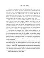
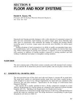
7.3 EXAMPLE—LRFD FOR WIDE-FLANGE TRUSS MEMBERS
One-way, long-span trusses are to be used to frame the roof of a sports facility. The truss
span is 300 ft. All members are wide-flange sections. (See Fig. 7.1 for the typical detail of
the bottom-chord splice of the truss).
Connections of the truss diagonals and verticals to the bottom chord are bolted. Slip-
critical, the connections serve also as splices, with 1
1
⁄
8
-in-diameter A325 bolts, in oversized
holes to facilitate truss assembly in the field. The holes are 1
7
⁄
16
in in diameter. The bolts
are placed in two rows in each flange. The number of bolts per row is more than two. The
web of each member is also spliced with a plate with two rows of 1
1
⁄
8
-in-diameter A325
bolts.
The structural engineer analyzes the trusses as pin-ended members. Therefore, all mem-
bers are considered to be subject to axial forces only. Members of longspan trusses with
significant deflections and large, bolted, slip-critical connections, however, may have signif-
icant bending moments. (See Art. 7.15 for an example of a design for combined axial load
and bending moments.)
The factored axial tension in the bottom chord at midspan due to combined dead, live,
theatrical, and hanger loads supporting sky boxes is P
u
ϭ
2280 kips.
DESIGN OF BUILDING MEMBERS
7.5
With a wide-flange section of grade 50 steel (F
y
ϭ
50 ksi and F
u
ϭ
65 ksi), the required
minimum gross area, from Eq. (7.3), is
2
A
ϭ
P /
F
ϭ
2280/(0.9
ϫ
50)
ϭ
50.67 in
guy
Try a W14
ϫ
176 section with A
g
ϭ
51.8 in
2
, flange thickness t
ƒ
ϭ
1.31 in, and web thickness
t
w
ϭ
0.83 in. The net area is
A
ϭ
51.8
Ϫ
(2
ϫ
1.31
ϫ
1.4375
ϫ
2
ϩ
2
ϫ
0.83
ϫ
1.4375)
n
2
ϭ
41.88 in
Since all parts of the wide-flange section are connected at the splice connection, U
ϭ
1 for
determination of the effective area from Eq. (7.5). Thus A
e
ϭ
A
n
ϭ
41.88 in
2
. From Eq.
(7.4), the design strength is
P
ϭ
0.75
ϫ
65
ϫ
41.88
ϭ
2042 kips
Ͻ
2280 kips—NG
n
Try a W14
ϫ
193 with A
g
ϭ
56.8 in
2
, t
ƒ
ϭ
1.44 in, and t
w
ϭ
0.89 in. The net area is
A
ϭ
56.8
Ϫ
(2
ϫ
1.44
ϫ
1.4375
ϫ
2
ϩ
2
ϫ
0.89
ϫ
1.4375)
n
2
ϭ
45.96 in
From Eq. (7.4), the design strength is
P
ϭ
0.75
ϫ
65
ϫ
45.96
ϭ
2241 kips
Ͻ
2280 ksi—NG
n
Use the next size, W14
ϫ
211.
7.4 COMPRESSION MEMBERS
Steel members in buildings subject to compressive axial loads include columns, truss mem-
bers, struts, and diagonal braces. Slenderness is a major factor in design of compression
members. The slenderness ratio L / r is preferably limited to 200. Most suitable steel shapes
are pipes, tubes, or wide-flange sections, as designated for columns in the AISC ‘‘Steel
Construction Manual.’’ Double angles, however, are commonly used for diagonal braces and
truss members. Double angles can be easily connected to other members with gusset plates
and bolts or welds.
The AISC ‘‘LRFD Specification for Structural Steel Buildings,’’ American Institute of
Steel Construction, gives the nominal strength P
n
(kips) of a steel section in compression as
P
ϭ
AF (7.6)
ngcr
The factored load P
u
(kips) may not exceed
P
ϭ
P
ϭ
0.85 (7.7)
un
The critical compressive stress F
cr
(kips) is a function of material strength and slenderness.
For determination of this stress, a column slenderness parameter
c
is defined as
KL F KL F
yy
ϭϭ
(7.8)
c
ΊΊ
r
Er286,220
where A
ϭ
g
gross area of the member, in
2
K
ϭ
effective length factor (Art. 6.16.2)
7.6
SECTION SEVEN
L
ϭ
unbraced length of member, in
F
y
ϭ
yield strength of steel, ksi
E
ϭ
modulus of elasticity of steel material, ksi
r
ϭ
radius of gyration corresponding to plane of buckling, in
When
c
Յ
1.5, the critical stress is given by
2
c
F
ϭ
(0.658 )F (7.9)
cr y
When
c
Ͼ
1.5,
0.877
F
ϭ
F (7.10)
ͩͪ
cr y
2
c
7.5 EXAMPLE—LRFD FOR STEEL PIPE IN AXIAL COMPRESSION
Pipe sections of A36 steel are to be used to support framing for the flat roof of a one-story
factory building. The roof height is 18 ft from the tops of the steel roof beams to the finish
of the floor. The steel roof beams are 16 in deep, and the bases of the steel-pipe columns
are 1.5 ft below the finished floor. A square joint is provided in the slab at the steel column.
Therefore, the concrete slab does not provide lateral bracing. The effective height of the
column, from the base of the column to the center line of the steel roof beam, is
16
h
ϭ
18
ϩ
1.5
Ϫϭ
18.83 ft
2
ϫ
12
The dead load on the column is 30 kips. The live load due to snow at the roof is 36 kips.
The factored axial load is the larger of the following:
P
ϭ
30
ϫ
1.4
ϭ
42 kips
u
P
ϭ
30
ϫ
1.2
ϩ
36
ϫ
1.6
ϭ
93.6 kips (governs)
u
With the factored load known, the required pipe size may be obtained from a table in the
AISC ‘‘Manual of Steel Construction—LRFD.’’ For KL
ϭ
19 ft, a standard 6-in pipe (weight
18.97 lb per linear ft) offers the least weight for a pipe with a compression-load capacity of
at least 93.6 kips. For verification of this selection, the following computations for the column
capacity were made based on a radius of gyration r
ϭ
2.25 in. From Eq. (7.8),
18.83
ϫ
12 36
ϭϭ
1.126
Ͻ
1.5
c
Ί
2.25 286,220
and
c
2
ϭ
1.269. For
c
Ͻ
1.5, Eq. (7.9) yields the critical stress
1.269
F
ϭ
0.658
ϫ
36
ϭ
21.17 ksi
cr
The design strength of the 6-in pipe, then, from Eqs. (7.6) and (7.7), is
P
ϭ
0.85
ϫ
5.58
ϫ
21.17
ϭ
100.4 kips
Ͼ
93.6 kips—OK
n
DESIGN OF BUILDING MEMBERS
7.7
7.6 COMPARATIVE DESIGNS OF WIDE-FLANGE SECTION WITH
AXIAL COMPRESSION
A wide-flange section is to be used for columns in a five-story steel building. A typical
interior column in the lowest story will be designed to support gravity loads. (In this example,
no eccentricity will be assumed for the load.) The effective height of the column is 18 ft.
The axial loads on the column from the column above and from the steel girders supporting
the second level are dead load 420 kips and live load (reduced according to the applicable
building code) 120 kips.
7.6.1 LRFD for W Section with Axial Compression
The factored axial load is the larger of the following:
P
ϭ
420
ϫ
1.4
ϭ
588 kips
u
P
ϭ
420
ϫ
1.2
ϩ
120
ϫ
1.6
ϭ
696 kips (governs)
u
To select the most economical section and material, assume that grade 36 steel costs
$0.24 per pound and grade 50 steel costs $0.26 per pound at the mill. These costs do not
include the cost of fabrication, shipping, or erection, which will be considered the same for
both grades.
Use of the column design tables of the AISC ‘‘Manual of Steel Construction—LRFD’’
presents the following options:
For the column of grade 36 steel, select a W14
ϫ
99, with a design strength
P
n
ϭ
745
kips.
Cost
ϭ
99
ϫ
18
ϫ
0.24
ϭ
$428
For the column of grade 50 steel, select a W12
ϫ
87, with a design strength
P
n
ϭ
758
kips.
Cost
ϭ
87
ϫ
18
ϫ
0.26
ϭ
$407
Therefore, the W12
ϫ
87 of grade 50 steel is the most economical wide-flange section.
7.6.2 ASD for W Section with Axial Compression
The dead- plus live-load axial compression totals 420
ϩ
120
ϭ
540 kips (Art. 7.6.1).
Column design tables in the AISC ‘‘Steel Construction Manual—ASD’’ facilitate selection
of wide-flange sections for various loads for columns of grades 36 and 50 steels.
For the column of grade 36 steel, with the slenderness ratio KL
ϭ
18 ft, the manual tables
indicate that the least-weight section with a capacity exceeding 540 kips is a W14
ϫ
109.
It has an axial load capacity of 564 kips. Estimated cost of the W14
ϫ
109 is $0.24
ϫ
109
ϫ
18
ϭ
$471.
LRFD requires a W14
ϫ
99 of grade 36 steel, with an estimated cost of $428. Thus the
cost savings by use of LRFD is 100(471
Ϫ
428)/428
ϭ
9.1%.
For the column of grade 50 steel, with KL
ϭ
18 ft, the manual tables indicate that the
least-weight section with a capacity exceeding 540 kips is a W14
ϫ
90. It has an axial
7.8
SECTION SEVEN
compression capacity of 609 kips. Estimated cost of the W14
ϫ
90 is $0.26
ϫ
90
ϫ
18
ϭ
$421. Thus the grade 50 column costs less than the grade 36 column.
LRFD requires a W12
ϫ
87 of grade 50 steel, with an estimated cost of $407. The cost
savings by use of LRFD is 100(421
Ϫ
407)421
ϭ
3.33%.
This example indicates that when slenderness is significant in design of compression
members, the savings with LRFD are not as large for slender members as for stiffer members,
such as short columns or columns with a large radius of gyration about the x and y axes.
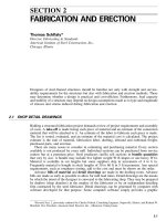
7.7 EXAMPLE—LRFD FOR DOUBLE ANGLES WITH AXIAL
COMPRESSION
Double angles are the preferred steel shape for a diagonal in the vertical bracing part of the
lateral framing system in a multistory building (Fig. 7.2). Lateral load on the diagonal in
this example is due to wind only and equals 65 kips. The diagonals also support the steel
beam at midspan. As a result, the compressive force on each brace due to dead loads is 15
kips, and that due to live loads is 10 kips. The maximum combined factored load is P
u
ϭ
1.2
ϫ
15
ϩ
1.3
ϫ
65
ϩ
0.5
ϫ
10
ϭ
107.5 kips.
The length of the brace is 19.85 ft, neglecting the size of the joint. Grade 36 steel is
selected because slenderness is a major factor in determining the nominal capacity of the
section. Selection of the size of double angles is based on trial and error, which can be
assisted by load tables in the AISC ‘‘Manual of Steel Construction—LRFD’’ for columns of
various shapes and sizes. For the purpose of illustration of the step-by-step design, double
angles 6
ϫ
4
ϫ
5
⁄
8
in with
3
⁄
8
-in spacing between the angles are chosen. Section properties
are as follows: gross area A
g
ϭ
11.7 in
2
and the radii of gyration are r
x
ϭ
1.90 in and r
y
ϭ
1.67 in.
First, the slenderness effect must be evaluated to determine the corresponding critical
compressive stresses. The effect of the distance between the spacer plates connecting the
two angles is a design consideration in LRFD. Assuming that the connectors are fully tight-
ened bolts, the system slenderness is calculated as follows:
The AISC ‘‘LRFD Specification for Structural Steel Buildings’’ defines the following
modified column slenderness for a built-up member:
22
2
KL KL
␣
a
ϭϩ
0.82 (7.11)
ͩͪ ͩͪ ͩͪ
2
Ί
rr1
ϩ
␣
r
ib
mo
where:
ϭ
KL
ͩͪ
r
o
column slenderness of built-up member acting as a unit
␣
ϭ
separation ratio
ϭ
h/2r
ib
h
ϭ
distance between centroids of individual components perpendicular to
member axis of buckling
a
ϭ
distance between connectors
r
ib
ϭ
radius of gyration of individual angle relative to its centroidal axis parallel
to member axis of buckling
In this case, h
ϭ
1.03
ϩ
0.375
ϩ
1.03
ϭ
2.44 in and
␣
ϭ
2.44/(2
ϫ
1.13)
ϭ
1.08. Assume
maximum spacing between connectors is a
ϭ
80 in. With K
ϭ
1, substitution in Eq. 7.11
yields
22
2
KL 19.85
ϫ
12 1.08 80
ϭϩ
0.82
ϭ
150
ͩͪ ͩ ͪ ͩ ͪ
2
Ί
r 1.67 1
ϩ
1.08 1.13
m
From Eq. 7.8, for determination of the critical stress F
cr
,
DESIGN OF BUILDING MEMBERS
7.9
FIGURE 7.2 Inverted V-braces in a lateral bracing bent.
36
ϭ
150
ϭ
1.68
Ͼ
1.5
c
Ί
286,220
The critical stress, from Eq. (7.10), then is
0.877
F
ϭ
36
ϭ
11.19 ksi
ͩͪ
cr
2
1.68
From Eqs. (7.6) and (7.7), the design strength is
P
ϭ
0.85
ϫ
11.7
ϫ
11.19
ϭ
111.3 kips
Ͼ
107.5 kips—OK
n
7.10
SECTION SEVEN
7.8 STEEL BEAMS
According to the AISC ‘‘LRFD Specification for Structural Steel Buildings,’’ the nominal
capacity M
p
(in-kips) of a steel section in flexure is equal to the plastic moment:
M
ϭ
ZF (7.12)
py
where Z is the plastic section modulus (in
3
), and F
y
is the steel yield strength (ksi). But this
applies only when local or lateral torsional buckling of the compression flange is not a
governing criterion. The nominal capacity M
p
is reduced when the compression flange is not
braced laterally for a length that exceeds the limiting unbraced length for full plastic bending
capacity L
p
. Also, the nominal moment capacity is less than M
p
, when the ratio of the
compression-element width to its thickness exceeds limiting slenderness parameters for com-
pact sections. The same is true for the effect of the ratio of web depth to thickness. (See
Arts. 6.17.1 and 6.17.2.)
In addition to strength requirements for design of beams, serviceability is important.
Deflection limitations defined by local codes or standards of practice must be maintained in
selecting member sizes. Dynamic properties of the beams are also important design para-
meters in determining the vibration behavior of floor systems for various uses.
The shear forces in the web of wide-flange sections should be calculated, especially if
large concentrated loads occur near the supports. The AISC specification requires that the
factored shear V
v
(kips) not exceed
V
ϭ
V
ϭ
0.90 (7.13)
uun
v
where
v
is a capacity reduction factor and V
n
is the nominal shear strength (kips). For h /
t
w
Յ
187 ,
͙
k / F
v
yw
V
ϭ
0.6FA (7.14)
nyww
where h
ϭ
clear distance between flanges (less the fillet or corner radius for rolled shapes),
in
k
v
ϭ
web-plate buckling coefficient (Art. 6.14.1)
t
w
ϭ
web thickness, in
F
yw
ϭ
yield strength of the web, ksi
A
w
ϭ
web area, in
2
For 187
Ͻ
h/t
w
Յ
234
͙
k / F
͙
k / F ,
v
yw
v
yw
187
͙
k / F
v
yw
V
ϭ
0.6FA (7.15)
nyww
h/t
w
For h / t
w
Ͼ
234 ,
͙
k / F
v
yw
26,400k
v
V
ϭ
A (7.16)
nw
2
(h/t )
w
2
k
ϭ
5
ϩ
5/(a
ϩ
h)
v
2
ϭ
5 when a/ h
Ͼ
3ora/ h
Ͼ
[260/(h/ t)] (7.17)
ϭ
5 if no stiffeners are used
where a
ϭ
distance between transverse stiffeners
DESIGN OF BUILDING MEMBERS
7.11
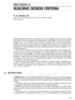
7.9 COMPARATIVE DESIGNS OF SIMPLE-SPAN FLOORBEAM
Floor framing for an office building is to consist of open-web steel joists with a standard
corrugated metal deck and 3-in-thick normal-weight concrete fill. The joists are to be spaced
3 ft center to center. Steel beams spanning 30 ft between columns support the joists. A bay
across the building floor is shown in Fig. 7.3.
Floorbeam AB in Fig. 7.3 will be designed for this example. The loads are listed in Table
7.1. The live load is reduced in Table 7.1, as permitted by the Uniform Building Code. The
reduction factor R is given by the smaller of
R
ϭ
0.0008(A
Ϫ
150) (7.18)
R
ϭ
0.231(1
ϩ
D/L) (7.19)
R
ϭ
0.4 for beams (7.20)
where D
ϭ
dead load
L
ϭ
live load
A
ϭ
area supported
ϭ
30(40
ϩ
25)/2
ϭ
975 ft
2
From Eq. (7.18), R
ϭ
0.0008(975
Ϫ
150)
ϭ
0.66.
From Eq. (7.19), R
ϭ
0.231(1
ϩ
73
⁄
50
)
ϭ
0.568.
From Eq. (7.20), R
ϭ
0.4 (governs), and the reduced live load is 50(10.4)
ϭ
30 lb per
ft
2
, as shown in Table 7.1.
7.9.1 LRFD for Simple-Span Floorbeam
If the beam’s self-weight is assumed to be 45 lb/ft, the factored uniform load is the larger
of the following:
W
ϭ
1.4[73(40
ϩ
25)/2
ϩ
45]
ϭ
3384.5 lb per ft
u
W
ϭ
1.2[73(40
ϩ
25)/2
ϩ
45]
ϩ
1.6
ϫ
30(40
ϩ
25)/2
u
ϭ
4461 lb per ft (governs)
The factored moment then is
2
M
ϭ
4.461(30) /8
ϭ
501.9 kip-ft
u
To select for beam AB a wide-flange section with F
y
ϭ
50 ksi, the top flange being braced
by joists, the required plastic modulus Z
x
is determined as follows:
The factored moment M
u
may not exceed the design strength of
M
r
, and
M
ϭ
ZF (7.21)
rxy
Therefore, from Eq. (7.21),
501.9
ϫ
12
3
Z
ϭϭ
133.8 in
x
0.9
ϫ
50
A wide-flange section W24
ϫ
55 with Z
ϭ
134 in
3
is adequate.
Next, criteria are used to determine if deflections are acceptable. For the live-load de-
flection, the span L is 30 ft, the moment of inertia of the W24
ϫ
55 is l
ϭ
1350 in
4
, and
7.12
SECTION SEVEN
FIGURE 7.3 Part of the floor framing for an office building.
DESIGN OF BUILDING MEMBERS
7.13
TABLE 7.1
Loads on Floorbeam AB in Fig. 7.3
Dead loads, lb per ft
2
Floor deck 45
Ceiling and mechanical ductwork 5
Open-web joists 3
Partitions 20
Total dead load (exclusive of beam weight) 73
Live loads, lb per ft
2
Full live load 50
Reduced live load: 50(1
Ϫ
0.4) 30
the modulus of elasticity E
ϭ
29,000 ksi. The live load is W
L
ϭ
30(40
ϩ
25)/2
ϭ
975 lb
per ft. Hence the live-load deflection is
443
5WL 5
ϫ
0.975
ϫ
30
ϫ
12
L
⌬ ϭϭ ϭ
0.454 in
L
394EI 384
ϫ
29,000
ϫ
1,350
This value is less than L / 360
ϭ
30
ϫ
12
⁄
360
ϭ
1 in, as specified in the Uniform Building
Code (UBC). The UBC requires that deflections due to live load plus a factor K times
deadload not exceed L/240. The K value, however, is specified as zero for steel. [The intent
of this requirement is to include the long-term effect (creep) due to dead loads in the de-
flection criteria.] Hence the live-load deflection satisfies this criterion.
The immediate deflection due to the weight of the concrete and the floor framing is also
commonly determined. If excessive deflections due to such dead loads are found, it is rec-
ommended that steel members be cambered to produce level floors and to avoid excessive
concrete thickness during finishing the wet concrete.
In this example, the load due to the weight of the floor system is from Table 7.1 with
the weight of the beam added,
W
ϭ
(45
ϩ
3)(40
ϩ
25)/2
ϩ
55
ϭ
1615 lb per ft
wt
The deflection due to this load is
4
5
ϫ
1.615
ϫ
30
ϫ
12
⌬ ϭϭ
0.752 in
wt
384
ϫ
29,000
ϫ
1,350
Therefore, cambering the beam
3
⁄
4
in at midspan is recommended.
For review of the shear capacity of the section, the depth/thickness ratio of the web is
5
h/t
ϭ
54.6
Ͻ
(187
͙
⁄
50
ϭ
59.13)
w
From Eq. (7.14), the design shear strength is
V
ϭ
0.9
ϫ
0.6
ϫ
50
ϫ
23.57
ϫ
0.395
ϭ
251 kips
n
The factored shear force near the support is
V
ϭ
4.461
ϫ
30/2
ϭ
66.92 kips
Ͻ
251 kips—OK
u
As illustrated in this example, it usually is not necessary to review the design of each simple
beam with uniform load for shear capacity.
7.14
SECTION SEVEN
7.9.2 ASD for Simple-Span Floorbeam
The maximum moment due to the dead and live loads provided for Art. 7.9.1 is calculated
as follows.
The total service load, after allowing a reduction in live load for size of area supported,
is 73
ϩ
30
ϭ
103 lb per ft
2
. Assume that the beam weighs 60 lb per ft. Then, the total
uniform load on the beam is
W
ϭ
103
ϫ
0.5(40
ϩ
25)
ϩ
60
ϭ
3408 lb per ft
ϭ
3.408 kips per ft
t
For this load, the maximum moment is
2
M
ϭ
3.408
ϫ
30 /8
ϭ
383.4 kip-ft
For an allowable stress F
b
ϭ
0.66F
y
ϭ
0.66
ϫ
50
ϭ
33 ksi, the required section modulus
for the floorbeam is
3
S
ϭ
M/F
ϭ
383.4
ϫ
12/33
ϭ
139.4 in
rb
The least-weight wide-flange section with S exceeding 139.4 is a W21
ϫ
68 or a W24
ϫ
68. (If depth is not important, choose the latter because it will deflect less.)
LRFD requires a W24
ϫ
55. The weight saving with LRFD is 100(68
Ϫ
55)/68
ϭ
19.1%.
The percentage savings in weight with LRFD differs significantly from that in this ex-
ample for a different ratio of live load to dead load. When live loads are relatively large,
such as 100 psf for occupancy load in public areas, the savings in steel tonnage with LRFD
is not as large as this example indicates.
Deflection calculation for ASD of the floorbeam is similar to that performed in Art. 7.9.1.
For review of shear stresses, the depth / thickness ratio of the web of the W24
ϫ
68 is
h/t
w
ϭ
21/0.415
ϭ
50.6. Since this is less than 380 /
ϭ
380/
ϭ
53.7, the allowable
͙
F
͙
50
y
shear stress is F
v
ϭ
0.4
ϫ
50
ϭ
20 ksi. The vertical shear at the support is V
ϭ
3.408
ϫ
30
⁄
2
ϭ
51.12 kips. Hence the shear stress there is
ƒ
ϭ
51.12/23.73
ϫ
0.415
ϭ
5.19 ksi
Ͻ
20 ksi—OK
v
7.10 EXAMPLE—LRFD FOR FLOORBEAM WITH UNBRACED
TOP FLANGE
A beam of grade 50 steel with a span of 20 ft is to support the concentrated load of a stub
pipe column at midspan. The factored concentrated load is 55 kips. No floor deck is present
on either side of the beam to brace the top flange, and the pipe column is not capable of
bracing the top flange laterally. The weight of the beam is assumed to be 50 lb/ft.
The factored moment at midspan is
2
M
ϭ
55
ϫ
20/4
ϩ
0.050
ϫ
20 /8
ϭ
277.5 kip-ft
u
A beam size for a first trial can be selected from a load-factor design table for steel with
F
y
ϭ
50 ksi in the AISC ‘‘Steel Construction Manual—LRFD.’’ The table lists several
properties of wide-flange shapes, including plastic moment capacities
M
p
. For example, an
examination of the table indicates that the lightest beam with
M
p
exceeding 277.5 kip-ft is
a W18
ϫ
40 with
M
p
ϭ
294 kip-ft. Whether this beam can be used, however, depends on
the resistance of its top flange to buckling. The manual table also lists the limiting laterally
unbraced lengths for full plastic bending capacity L
p
and inelastic torsional buckling L
r
.For
the W18
ϫ
40, L
p
ϭ
4.5 ft and L
r
ϭ
12.1 ft (Table 7.2).
DESIGN OF BUILDING MEMBERS
7.15
TABLE 7.2
Properties of Selected W Shapes for LRFD
Property W18
ϫ
35 grade 36 W18
ϫ
40 grade 50 W21
ϫ
50 grade 50 W21
ϫ
62 grade 50
M
p
, kip-ft 180 294 413 540
L
p
, ft 5.1 4.5 4.6 6.3
L
r
, ft 14.8 12.1 12.5 16.6
M
r
, kip-ft 112 205 283 381
S
x
,in
3
57.6 68.4 94.5 127
X
1
, ksi 1590 1810 1730 1820
X
2
, 1/ksi
2
0.0303 0.0172 0.0226 0.0159
r
y
, in 1.22 1.27 1.30 1.77
In this example, then, the 20-ft unbraced beam length exceeds L
r
. For this condition, the
nominal bending capacity M
n
is given by Eq. (6.54): M
n
ϭ
M
cr
Յ
C
n
M
r
. For a simple beam
with a concentrated load, the moment gradient C
b
is unity. From the table in the manual for
the W18
ϫ
40 (grade 50), design strength
M
r
ϭ
205 kip-ft
Ͻ
277.5 kip-ft. Therefore, a
larger size is necessary.
The next step is to find a section that if its L
r
is less than 20 ft, its M
r
exceeds 277.5 kip-
ft. The manual table indicated that a W21
ϫ
50 has the required properties (Table 7.2). With
the aid of Table 7.2, the critical elastic moment capacity
M
cr
can be computed from
2
CSX
͙
2
XX
bx 1
12
M
ϭ
0.90 1
ϩ
(7.22)
cr
2
Ί
L /r 2(L /r )
by by
The beam slenderness ratio with respect to the y axis is
L /r
ϭ
20
ϫ
12/1.30
ϭ
184.6
by
Thus the critical elastic moment capacity is
2
1
ϫ
94.5
ϫ
1,730
͙
2
1,730
ϫ
0.0226
M
ϭ
0.90 1
ϩ
cr
2
Ί
184.6 2(184.6)
ϭ
1,591 kip-in
ϭ
132.6 kip-ft
Ͻ
277.5 kip-ft
The W21
ϫ
50 does not have adequate capacity. Therefore, trials to find the lowest-weight
larger size must be continued. This trial-and-error process can be eliminated by using beam-
selector charts in the AISC manual. These charts give the beam design moment correspond-
ing to unbraced length for various rolled sections. Thus for
M
r
Ͼ
277.5 kip-ft and L
ϭ
20
ft, the charts indicate that a W21
ϫ
62 of grade 50 steel satisfies the criteria (Table 7.2). As
a check, the following calculation is made with the properties of the W21
ϫ
62 given in
Table 7.2.
For use in Eq. (7.22), the beam slenderness ratio is
L /r
ϭ
20
ϫ
12/1.77
ϭ
135.6
by
From Eq. (7.22), the critical elastic moment capacity is
2
1
ϫ
127
ϫ
1820
͙
2
1820
ϫ
0.0159
M
ϭ
0.9 1
ϩ
cr
2
Ί
135.6 (135.6)
ϭ
3384 kip-in
ϭ
282 kip-ft
Ͼ
277.5 kip-ft—OK