Sổ tay kết cấu thép - Section 8
Bạn đang xem bản rút gọn của tài liệu. Xem và tải ngay bản đầy đủ của tài liệu tại đây (579.01 KB, 35 trang )
8.1
SECTION 8
FLOOR AND ROOF SYSTEMS
Daniel A. Cuoco, P.E.
Principal, LZA Technology/Thornton-Tomasetti Engineers,
New York, New York
Structural-steel framing provides designers with a wide selection of economical systems for
floor and roof construction. Steel framing can achieve longer spans more efficiently than
other types of construction. This minimizes the number of columns and footings thereby
increasing speed of erection. Longer spans also provide more flexibility for interior-space
planning.
Another advantage of steel construction is its ability to readily accommodate future struc-
tural modifications, such as openings for tenants’ stairs and changes for heavier floor load-
ings. When reinforcement of existing steel structures is required, it can be accomplished by
such measures as addition of framing members connected to existing members and field
welding of additional steel plates to strengthen existing members.
FLOOR DECK
The most common types of floor-deck systems currently used with structural steel construc-
tion are concrete fill on metal deck, precast-concrete planks, and cast-in-place concrete slabs.
8.1 CONCRETE FILL ON METAL DECK
The most prevalent type of floor deck used with steel frames is concrete fill on metal deck.
The metal deck consists of cold-formed profiles made from steel sheet, usually having a
yield strength of at least 33 ksi. Design requirements for metal deck are contained in the
American Iron and Steel Institute’s ‘‘Specification for the Design of Cold-Formed Steel
Structural Members.’’
The concrete fill is usually specified to have a 28-day compressive strength of at least
3000 psi. Requirements for concrete design are contained in the American Concrete Institute
Standard ACI 318, ‘‘Building Code Requirements for Reinforced Concrete.’’
Sheet thicknesses of metal deck usually range between 24 and 18 ga, although thicknesses
outside this range are sometimes used. The design thicknesses corresponding to typical gage
designations are shown in Table 8.1.
8.2
SECTION EIGHT
TABLE 8.1
Equivalent Thicknesses for
Cold-Formed Steel
Gage
designation
Design
thickness, in
28 0.0149
26 0.0179
24 0.0239
22 0.0299
20 0.0359
18 0.0478
16 0.0598
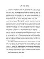
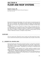
FIGURE 8.1 Cold-formed steel decking used in composite construction with concrete fill.
Metal deck is commonly available in depths of 1
1
⁄
2
, 2, and 3 in. Generally, it is preferable
to use a deeper deck that can span longer distances between supports and thereby reduce
the number of beams required. For example, a beam spacing of about 15 ft can be achieved
with 3-in deck. However, each project must be evaluated on an individual basis to determine
the most efficient combination of deck depth and beam spacing.
For special long-span applications, metal deck is available with depths of 4
1
⁄
2
, 6, and 7
1
⁄
2
in from some manufacturers.
Composite versus Noncomposite Construction. Ordinarily, composite construction with
metal deck and structural-steel framing is used. In this case, the deck acts not only as a
permanent form for the concrete slab but also, after the concrete hardens, as the positive
bending reinforcement for the slab. To achieve this composite action, deformations are
formed in the deck to provide a mechanical interlock with the concrete (Fig. 8.1). Although
not serving a primary structural purpose, welded wire fabric is usually placed within the
concrete slab about 1 in below the top surface to minimize cracking due to concrete shrinkage
and thermal effects. This welded wire fabric also provides, to a limited degree, some amount
of crack control in negative-moment regions of the slab over supporting members.
FLOOR AND ROOF SYSTEMS
8.3
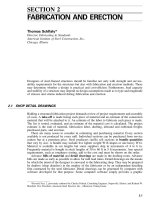
FIGURE 8.2 Cellular steel deck with concrete slab.
Noncomposite metal deck is used as a form for concrete and is considered to be ineffective
in resisting superimposed loadings. In cases where the deck is shored, or where the deck is
unshored but the long-term reliability of the deck will be questionable, the deck is also
considered to be ineffective in supporting the dead load of the concrete slab. For example,
in regions where deicing chemicals are applied to streets, metal deck used in parking struc-
tures is susceptible to corrosion and may eventually be ineffective unless special precautions
are taken. In such cases, the metal deck should be used solely as a form to support the
concrete until it hardens. Reinforcement should be placed within the slab to resist all design
loadings.
Noncellular versus Cellular Deck. It is sometimes desirable to distribute a building’s elec-
trical wiring within the floor deck system, in which case cellular metal deck can be used in
lieu of noncellular deck. However, in cases where floor depth is not critical, maximum wiring
flexibility and capacity can be attained by using a raised access floor above the structural
floor deck.
Cellular deck is essentially noncellular deck, such as that shown in Fig. 8.1, with a flat
sheet added to the bottom of the deck to create cells (Fig. 8.2). Electrical, power, and
telephone wiring is placed within the cells for distribution over the entire floor area. In many
cases, a sufficient number of cells is obtained by combining alternate panels of cellular deck
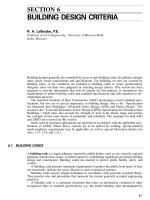
and noncellular deck, which is called a blended system (Fig. 8.3). When cellular deck is
used, the 3-in depth is the minimum preferred because it provides convenient space for
wiring. The 1
1
⁄
2
-in depth is rarely used.
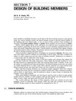
For feeding wiring into the cells, a trench header is placed within the concrete above the
metal deck, in a direction perpendicular to the cells (Fig. 8.4). Special attention should be
given to the design of the structural components adjacent to the trench header, since com-
posite action for both the floor deck and beams is lost in these areas. Where possible, the
direction of the cells should be selected to minimize the total length of trench header re-
8.4
SECTION EIGHT
FIGURE 8.3 Blended deck, alternating cellular and noncellular panels, in composite construction.
CONCRETE
SLAB
AIR CELLS
SPRAY-ON FIREPROOFING
(NOT ALWAYS REQUIRED)
ELECTRICAL
CELLS
TRENCH
HEADERS
FIGURE 8.4 Cellular steel deck with trench header placed within the concrete slab to feed wiring
to cells.
quired. Generally, by running the cells in the longitudinal direction of the building, the total
length of trench header is significantly less than if the cells were run in the transverse
direction (Fig. 8.5).
If a uniform grid of power outlets is desired, such as 5 ft by 5 ft on centers, preset outlets
can be positioned above the cells and cast into the concrete fill. However, in many cases the
outlet locations will be dictated by subsequent tenant layouts. In such cases, the concrete fill
can be cored and afterset outlets can be installed at any desired location.
Shored versus Unshored Construction. To support the weight of newly placed concrete
and the construction live loads applied to the metal deck, the deck can either be shored or
be designed to span between supporting members. If the deck is shored, a shallower-depth
8.5
FIGURE 8.5 Floor layout for cellular deck with cells in different directions. Length of trench header serving
them is less for (a) cells in the longitudinal direction than for (b) cells in the transverse direction.
8.6
SECTION EIGHT
or thinner-gage deck can be used. The economy of shoring, however, should be investigated,
inasmuch as the savings in deck cost may be more than offset by the cost of the shoring.
Also, slab deflections that will occur after the shoring is removed should be evaluated, as
well as concrete cracking over supporting members. Another consideration is that use of
shoring can sometimes affect the construction schedule, since the shoring is usually kept in
place until the concrete fill has reached at least 75% of its specified 28-day compressive
strength. In addition, when shoring is used, the concrete must resist the stresses resulting
from the total dead load combined with all superimposed loadings.
When concrete is cast on unshored metal deck, the weight of the concrete causes the
deck to deflect between supports. This deflection is usually limited to the lesser of
1
⁄
180
the
deck span or
3
⁄
4
in. If the resulting effect on floor flatness is objectionable, the top surface
can be finished level, but this will result in additional concrete being placed to compensate
for the deflection. The added weight of this additional concrete must be taken into account
in design of the metal deck to ensure adequate strength. The concrete fill, however, need
only resist the stresses resulting from superimposed loadings.
Unshored metal-deck construction is the system most commonly used. The additional
cost of the deeper or thicker deck is generally much less than the cost of shoring. To increase
the efficiency of the unshored deck in supporting the weight of the unhardened concrete and
construction live loads, from both a strength and deflection standpoint, the deck is normally
extended continuously over supporting members for two or three spans, in lieu of single-
span construction. However, for loadings once the concrete is hardened, the composite slab
is designed for the total load, including slab self-weight, with the slab treated as a single
span, unless negative-moment reinforcement is provided over supports in accordance with
conventional reinforced-concrete-slab design (disregarding the metal deck as compressive
reinforcement).
Lightweight versus Normal-Weight Concrete. Either lightweight or normal-weight con-
crete can serve the structural function of the concrete fill placed on the metal deck. Although
there is a cost premium associated with lightweight concrete, sometimes the savings in steel
framing and foundation costs can outweigh the premium. Also, lightweight concrete in suf-
ficient thickness can provide the necessary fire rating for the floor system and thus eliminate
the need for additional slab fire protection (see ‘‘Fire Protection’’ below).
The tradeoffs in use of lightweight concrete versus normal-weight concrete plus fire pro-
tection should be evaluated on a project-by-project basis.
Fire Protection. Most applications of concrete fill on metal deck in buildings require that
the floor-deck assembly have a fire rating. For noncellular metal deck, the fire rating is
usually obtained either by providing sufficient concrete thickness above the metal deck or
by applying spray-on fire protection to the underside of the metal deck. For cellular metal
deck, which utilizes outlets that penetrate the concrete fill, the fire rating is usually obtained
by the latter method. As an alternative, a fire-rated ceiling system can be installed below the
cellular or noncellular deck.
When the required fire rating is obtained by concrete-fill thickness alone, lightweight
concrete requires a lesser thickness than normal-weight concrete for the same rating. For
example, a 2-hour rating can be obtained by using either 3
1
⁄
4
in of lightweight concrete or
4
1
⁄
2
in of normal-weight concrete above the metal deck. The latter option is rarely used,
since the additional thickness of heavier concrete penalizes the steel tonnage (i.e., heavier
beams, girders, and columns) and the foundations.
If spray-on fire protection is used on the underside of the metal deck, the thickness of
concrete above the deck can be the minimum required to resist the applied floor loads. This
minimum thickness is usually 2
1
⁄
2
in, and the less expensive normal-weight concrete may be
used instead of lightweight concrete. Therefore, the two options that are frequently consid-
ered for a 2-hour-rated, noncellular floor-deck system are 3
1
⁄
4
-in lightweight concrete above
FLOOR AND ROOF SYSTEMS
8.7
FIGURE 8.6 Two-hour fire-rated floor systems, with cold-formed steel deck. (a) With lightweight
concrete fill; (b) with normal-weight concrete fill.
the metal deck without spray-on fire protection and 2
1
⁄
2
-in normal-weight concrete above the
metal deck with spray-on fire protection (Fig. 8.6). Since the dead load of the floor deck for
the two options is essentially the same, the steel framing and foundations will also be the
same. Thus, the comparison reduces to the cost of the more expensive lightweight concrete
versus the cost of the normal-weight concrete plus the spray-on fire protection. Since the
costs, and contractor preferences, vary with geographical location, the evaluation must be
made on an individual project basis. (See also Art. 6.32.)
Diaphragm Action of Metal-Deck Systems. Concrete fill on metal deck readily serves as
a relatively stiff diaphragm that transfers lateral loads, such as wind and seismic forces, at
each floor level through in-plane shear to the lateral load-resisting elements of the structure,
such as shear walls and braced frames. The resulting shear stresses can usually be accom-
modated by the combined strength of the concrete fill and metal deck, without need for
additional reinforcement. Attachment of the metal deck to the steel framing, as well as
attachment between adjacent deck units, must be sufficient to transfer the resulting shear
stresses (see ‘‘Attachment of Metal Deck to Framing’’ below).
Additional shear reinforcement may be required in floor decks with large openings, such
as those for stairs or shafts, with trench headers for electrical distribution, or with other shear
discontinuities. Also, floors in multistory buildings in which cumulative lateral loads are
8.8
SECTION EIGHT
FIGURE 8.7 Precast-concrete plank floor with concrete topping.
transferred from one lateral load-resisting system to another (for example, from perimeter
frames to interior shear walls), may be subjected to unusually large shear stresses that require
a diaphragm strength significantly greater than that for a typical floor.
Attachment of Metal Deck to Framing. Metal deck can be attached to the steel framing
with puddle (arc spot) welds, screws, or powder-driven fasteners. These attachments provide
lateral bracing for the steel framing and, when applicable, transfer shear stresses resulting
from diaphragm action. The maximum spacing of attachments to steel framing is generally
12 in.
Attachment of adjacent deck units to each other, that is, sidelap connection, can be made
with welds, screws, or button punches. Generally, the maximum spacing of sidelap attach-
ments is 36 in. In addition to diaphragm or other loading requirements, the type, size, and
spacing of attachments is sometimes dictated by insurance (Factory Mutual or Underwriters’
Laboratories) requirements.
Weld sizes generally range between
1
⁄
2
-in and
3
⁄
4
-in minimum visible diameter. When
metal deck is welded to steel framing, welding washers should be used if the deck thickness
is less than 22 ga to minimize the possibility of burning through the deck. Sidelap welding
is not recommended for deck thicknesses of 22 ga and thinner.
Screws can be either self-drilling or self-tapping. Self-drilling screws have drill points
and threads formed at the screw end. This enables direct installation without the need for
predrilling of holes in the steel framing or metal deck. Self-tapping screws require that a
hole be drilled prior to installation. Typical screw sizes are No. 12 and No. 14 (with 0.216-
in and 0.242-in shank diameter, respectively) for attachment of metal deck to steel framing.
No. 8 and No. 10 screws (with 0.164-in and 0.190-in shank diameter, respectively) are
frequently used for sidelap connections.
Powder-driven fasteners are installed through the metal deck into the steel framing with
pneumatic or powder-actuated equipment. Predrilled holes are not required. These types of
fasteners are not used for sidelap connections.
Button punches can be used for sidelap connections of certain types of metal deck that
utilize upstanding seams at the sidelaps. However, since uniformity of installation is difficult
to control, button punches are not usually considered to contribute significantly to diaphragm
strength.
The diaphragm capacity of various types and arrangements of metal deck and attachments
are given in the Steel Deck Institute Diaphragm Design Manual.
8.2 PRECAST-CONCRETE PLANK
This is another type of floor deck that is used with steel-framed construction (Fig. 8.7). The
plank is prefabricated in standard widths, usually ranging between 4 and 8 ft, and is normally
prestressed with high-strength steel tendons. Shear keys formed at the edges of the plank
are subsequently grouted, to allow loads to be distributed between adjacent planks. Voids
are usually placed within the thickness of the plank to reduce the deadweight without causing
FLOOR AND ROOF SYSTEMS
8.9
significant reduction in plank strength. The inherent fire resistance of the precast concrete
plank obviates the need for supplementary fire protection.
Topped versus Untopped Planks. Precast planks can be structurally designed to sustain
required loadings without need for a cast-in-place concrete topping. However, in many cases,
it is advantageous to utilize a topping to eliminate differences in camber and elevation
between adjacent planks at the joints and thus provide a smooth slab top surface. When a
topping is used, the top surface of the plank may be intentionally roughened to achieve
composite action between topping and plank. Thereby, the topping also serves as a structural
component of the floor-deck system.
A cast-in-place concrete topping can also be used for embedment of conduits and outlets
that supply electricity and communication services. Voids within the planks can also be used
as part of the distribution system. When the topping is designed to act compositely with the
plank, however, careful consideration must be given to the effects of these embedded items.
Dead-Load Deflection of Concrete Plank. In design of prestressed-concrete planks, the
prestressing load balances a substantial portion of the dead load. As a result, relatively small
dead-load deflections occur. For planks subjected to significant superimposed dead-load con-
ditions of a sustained nature, for example, perimeter plank supporting an exterior masonry
wall, additional prestressing to compensate for the added dead load, or some other stiffening
method, is required to prevent large initial and creep deflections of the plank.
Diaphragm Action of Concrete-Plank Systems. The diaphragm action of a floor deck
composed of precast-concrete planks can be enhanced by making field-welded connections
between steel embedments located intermittently along the shear keys of adjacent planks.
(See also Art. 8.1.)
Attachments of Concrete Plank to Framing. Precast-concrete planks are attached to and
provide lateral bracing for supporting steel framing. A typical method of attachment is a
field-welded connection between the supporting steel and steel embedments in the precast
planks.
8.3 CAST-IN-PLACE CONCRETE SLABS
Use of cast-in-place concrete for floor decks in steel-framed construction is a traditional
approach that was much more prevalent prior to the advent of metal deck and spray-on fire
protection. For one of the more common types of cast-in-place concrete floors, the formwork
is configured to encase the steel framing, to provide fire protection and lateral bracing for
the steel (see Fig. 8.8). If the proper confinement details are provided, this encasement can
also serve to achieve composite action between the steel framing and the floor deck.
Dead-load deflections should be calculated and, for long spans with large deflections, the
formwork should be cambered to provide a level deck surface after removal of the formwork
shoring. Diaphragm action is readily attainable with cast-in-place concrete floor decks. (See
also Art. 8.1.)
ROOF DECKS
The systems used for floor decks (Arts. 8.1 to 8.3) can also be used for roof decks. When
used as roof decks, these systems are overlaid by roofing materials, to provide a weathertight
enclosure. Other roof deck systems are described in Arts. 8.4 to 8.7.
8.10
SECTION EIGHT
FIGURE 8.8 Minimum requirements for composite action with concrete-encased steel
framing.
8.4 METAL ROOF DECK
Steel-framed buildings often utilize a roof deck composed simply of metal deck. When
properly sloped for drainage, the metal deck itself can serve as a watertight enclosure. Al-
ternatively, roofing materials can be placed on top of the deck. In either case, diaphragm
action can be achieved by proper sizing and attachment of the metal deck. A fire rating can
be provided by applying spray-on fire protection to the underside of the roof deck, or by
installing a fire-rated ceiling system below the deck.
Metal roof deck usually is used for noncomposite construction. It is commonly available
in depths of 1
1
⁄
2
, 2, and 3 in. Long-span roof deck is available with depths of 4
1
⁄
2
,6,and
7
1
⁄
2
in from some manufacturers. Cellular roof deck is sometimes used to provide a smooth
soffit. When a lightweight insulating concrete fill is placed over the roof deck, the deck
should be galvanized and also vented (perforated) to accelerate the drying time of the in-
sulating fill, and prevent entrapment of water vapor.
Standing-Seam System. When the metal roof deck is to serve as a weathertight enclosure,
connection of deck units with standing seams offers the advantage of placing the deck seam
above the drainage surface of the roof, thereby minimizing the potential for water leakage
(Fig. 8.9). The seams can simply be snapped together or, to enhance their weathertightness,
can be continuously seamed by mechanical means with a field-operated seaming machine
provided by the deck manufacturer. Some deck types utilize an additional cap piece over the
seam, which is mechanically seamed in the field (see Fig. 8.10). Frequently, the seams
contain a factory-applied sealant for added weather protection.
Thicknesses of standing-seam roof decks usually range between 26 and 20 ga. Typical
spans range between 3 and 8 ft. A roof slope of at least
1
⁄
4
in per ft should be provided for
drainage of rainwater.
Standing-seam systems are typically attached to the supporting members with concealed
anchor clips (Fig. 8.11) that allow unimpeded longitudinal thermal movement of the deck
relative to the supporting structure. This eliminates buildup of stresses within the system and
possible leakage at connections. However, the effect on the lateral bracing of supporting
members must be carefully evaluated, which may result in a need for supplementary bracing.
An evaluation method is presented in the American Iron and Steel Institute’s ‘‘Specification
for the Design of Cold-Formed Steel Structural Members.’’ (See Art. 10.12.4.)
FLOOR AND ROOF SYSTEMS
8.11
FIGURE 8.9 Standing-seam roof deck. (a) With snapped seam; (b) with mechanical seam; (c)
steps in forming a seam.
8.5 LIGHTWEIGHT PRECAST-CONCRETE ROOF PANELS
Roof decks of lightweight precast-concrete panels typically span 5 to 10) ft between supports.
Panel thicknesses range from 2 to 4 in, and widths are usually 16 to 24 in. Depending on
the product, concrete density can vary from 50 to 115 lb per ft
3
. Certain types of panels
have diaphragm capacities depending upon the edge and support connections used. Many
panels can achieve a fire rating when used as part of an approved ceiling assembly.
The panels are typically attached to steel framing with cold-formed-steel clips (see Fig.
8.12). The joints between panels are cemented on the upper side, usually with an asphaltic
mastic compound. Insulation and roofing materials are normally placed on top of the panels.
Some panels are nailable for application of certain types of roof finishes, such as slate, tile,
and copper.
8.6 WOOD-FIBER PLANKS
Planks formed of wood fibers bonded with portland cement provide a lightweight roof deck
with insulating and acoustical properties. The typical density of this material ranges between
30 and 40 lb per ft
3
. Some plank types have diaphragm capacities. When used as part of an
approved ceiling assembly, many planks can achieve a fire rating.
8.12
SECTION EIGHT
(c)
FIGURE 8.10 Standing-seam roof deck with cap installed over the seams. (a) Channel cap with
flanges folded over lip of seam. (b) U-shaped cap clamps over clips on seam. (c) Steps in forming
a seam with clamped cap.
The planks are usually supported by steel bulb tees (Fig. 8.13), which are nominally
spaced 32 to 48 in on centers. The joint over the bulb tee is typically grouted with a gypsum-
concrete grout and roofing materials are applied to the top surface of the planks.
FLOOR AND ROOF SYSTEMS
8.13
ANCHOR CLIP
FIGURE 8.11 Typical anchor clip for standing-seam roof deck.
FIGURE 8.12 Typical clips for attachment of precast-concrete panels to steel framing. The
clips are driven into place for a wedge fit at diagonal corners of the panels. Minimum flange
width for supporting member is preferably 4 in.
8.7 GYPSUM-CONCRETE DECKS
Poured gypsum concrete is typically used in conjunction with steel bulb tees, formboards,
and galvanized reinforcing mesh (Fig. 8.14). Drainage slopes can be readily built into the
roof deck by varying the thickness of gypsum.
FLOOR FRAMING
With a large variety of structural steel floor-framing systems available, designers frequently
investigate several systems during the preliminary design stage of a project. The lightest
8.14
SECTION EIGHT
FIGURE 8.13 (a) Wood-fiber planks form roof deck. (b) Plank is supported by
a steel bulb tee.
framing system, although the most efficient from a structural engineering standpoint, may
not be the best selection from an overall project standpoint, since it may have such disad-
vantages as high fabrication costs, large floor-to-floor heights, and difficulties in interfacing
with mechanical ductwork.
Spandrel members are frequently subjected to torsional loadings induced by facade ele-
ments and thus require special consideration. In addition, design of these members is fre-
quently governed by deflection criteria established to avoid damage to, or to permit proper
functioning of, the facade construction.
8.8 ROLLED SHAPES
Hot-rolled, wide-flange steel shapes are the most commonly used members for multistory
steel-framed construction. These shapes, which are relatively simple to fabricate, are eco-
nomical for beams and girders with short to moderate spans. In general, wide-flange shapes
are readily available in several grades of steel, including ASTM A36 and the higher-strength
ASTM A572 and A992 steels.