Sổ tay kết cấu thép - Section 14
Bạn đang xem bản rút gọn của tài liệu. Xem và tải ngay bản đầy đủ của tài liệu tại đây (1.11 MB, 68 trang )
14.1
SECTION 14
ARCH BRIDGES
Arthur W. Hedgren, Jr., P.E.*
Senior Vice President, HDR Engineering, Inc.,
Pittsburgh, Pennsylvania
Basic principles of arch construction have been known and used successfully for centuries.
Magnificent stone arches constructed under the direction of engineers of the ancient Roman
Empire are still in service after 2000 years, as supports for aqueducts or highways. One of
the finest examples is the Pont du Gard, built as part of the water-supply system for the city
of Nıˆmes, France.
Stone was the principal material for arches until about two centuries ago. In 1779, the
first metal arch bridge was built. Constructed of cast iron, it carried vehicles over the valley
of the Severn River at Coalbrookedale, England. The bridge is still in service but now is
restricted to pedestrian traffic. Subsequently, many notable iron or steel arches were built.
Included was Eads’ Bridge, with three tubular steel arch spans, 502, 520, and 502 ft, over
the Mississippi River at St. Louis. Though completed in 1874, it now carries large daily
volumes of heavy highway traffic.
Until 1900, stone continued as a strong competitor of iron and steel. After 1900, concrete
became the principal competitor of steel for shorter-span arch bridges.
Development of structural steels made it feasible to construct long-span arches econom-
ically. The 1675-ft Bayonne Bridge, between Bayonne, N.J., and Staten Island, N.Y., was
completed in 1931. The 1000-ft Lewiston-Queenston Bridge over the Niagara River on the
United States–Canadian border was put into service in 1962. Availability of more high-
strength steels and improved fabrication techniques expanded the feasibility of steel arches
for long spans. Examples include the 1255-ft-span Fremont Bridge in Portland, Ore., finished
in 1973, and the 1700-ft-span New River Gorge Bridge near Fayetteville, W. Va., opened in
1977.
Nearly all the steel arches that have been built lie in vertical planes. Accordingly, this
section discusses design principles for such arches. A few arch bridges, however, have been
constructed with ribs inclined toward each other. This construction is effective in providing
lateral stability and offers good appearance. Also, the decrease in average distance between
the arch ribs of a bridge often makes possible the use of more economical Vierendeel-girder
bracing instead of trussed bracing. Generally, though, inclined arches are not practicable for
bridges with very wide roadways unless the span is very long, because of possible interfer-
ence with traffic clearances. Further, inclined arch ribs result in more complex beveled con-
nections between members.
*Revised from Sec. 13, ‘‘Arch Bridges,’’ by George S. Richardson (deceased), Richardson, Gordon and Associates,
Pittsburgh, in Structural Steel Designer’s Handbook, 1st ed., McGraw-Hill Book Company, New York.
14.2
SECTION FOURTEEN
14.1 TYPES OF ARCHES
In the most natural type of arch, the horizontal component of each reaction, or thrust, is
carried into a buttress, which also carries the vertical reaction. This type will be referred to
as the true arch. The application of arch construction, however, can be greatly expanded
economically by carrying the thrust through a tie, a tension member between the ends of
the span. This type will be referred to as a tied arch.
Either a truss or girder may be used for the arch member. Accordingly, arch bridges are
classified as trussed or solid-ribbed.
Arch bridges are also classified according to the degree of articulation. A fixed arch, in
which the construction prevents rotation at the ends of the span, is statically indeterminate,
so far as external reactions are concerned, to the third degree. If the span is articulated at
the ends, it becomes two-hinged and statically indeterminate to the first degree. In recent
years, most arch bridges have been constructed as either fixed or two-hinged. Sometimes a
hinge is included at the crown in addition to the end hinges. The bridge then becomes three-
hinged and statically determinate.
In addition, arch bridges are classified as deck construction when the arches are entirely
below the deck. This is the most usual type for the true arch. Tied arches, however, normally
are constructed with the arch entirely above the deck and the tie at deck level. This type
will be referred to as a through arch. Both true and tied arches, however, may be constructed
with the deck at some intermediate elevation between springing and crown. These types are
classified as half-through.
The arch also may be used as one element combined with another type of structure. For
example, many structures have been built with a three-span continuous truss as the basic
structure and with the central span arched and tied. This section is limited to structures in
which the arch type is used independently.
14.2 ARCH FORMS
A great variety of forms have been used for trussed or solid-ribbed arch brides. The following
are some of the principal forms used.
Lindenthal’s Hell Gate Bridge over the East River in New York has trusses deep at the
ends and shallow at the crown. The bottom chord is a regular arch form. The top chord
follows a reversed curve transitioning from the deep truss at the end to the shallow truss at
the center. Accordingly, it is customary to refer to arch trusses of this form as Hell-Gate-
type trusses. In another form commonly used, top and bottom chords are parallel. For a two-
hinged arch, a crescent-shaped truss is another logical form.
For solid-ribbed arches, single-web or box girders may be used. Solid-ribbed arches usu-
ally are built with girders of constant depth. Variable-depth girders, tapering from deep
sections at the springing to shallower sections at the crown, however, have been used oc-
casionally for longer spans. As with trussed construction, a crescent-shaped girder is another
possible form for a two-hinged arch.
Tied arches permit many variations in form to meet specific site conditions. In a true arch
(without ties), the truss or solid rib must carry both thrust and moment under variable loading
conditions. These stresses determine the most effective depth of truss or girder. In a tied
arch, the thrust is carried by the arch truss or solid rib, but the moment for variable loading
conditions is divided between arch and tie, somewhat in proportion to the respective stiff-
nesses of these two members. For this reason, for example, if a deep girder is used for the
arch and a very shallow member for the tie, most of the moment for variable loading is
carried by the arch rib. The tie acts primarily as a tension member. But if a relatively deep
member is used for the tie, it carries a high proportion of the moment, and a relatively
ARCH BRIDGES
14.3
shallow member may be used for the arch rib. In some cases, a truss has been used for the
arch tie in combination with a shallow, solid rib for the arch. This combination may be
particularly applicable for double-deck construction.
Rigid-framed bridges, sometimes used for grade-separation structures, are basically an-
other form of two-hinged or fixed arch. The generally accepted arch form is a continuous,
smooth-curve member or a segmental arch (straight between panel points) with breaks lo-
cated on a smooth-curve axis. For a rigid frame, however, the arch axis becomes rectangular
in form. Nevertheless, the same principles of stress analysis may be used as for the smooth-
curve arch form.
The many different types and forms of arch construction make available to bridge engi-
neers numerous combinations to meet variable site conditions.
14.3 SELECTION OF ARCH TYPE AND FORM
Some of the most important elements influencing selection of type and form of arch follow.
Foundation Conditions. If a bridge is required to carry a roadway or railroad across a
deep valley with steep walls, an arch is probably a feasible and economical solution. (This
assumes that the required span is within reasonable limits for arch construction.) The con-
dition of steep walls indicates that foundation conditions should be suitable for the construc-
tion of small, economical abutments. Generally, it might be expected that under these con-
ditions the solution would be a deck bridge. There may be other controls, however, that
dictate otherwise. For example, the need for placing the arch bearings safely above high-
water elevation, as related to the elevation of the deck, may indicate the advisability of a
half-through structure to obtain a suitable ratio of rise to span. Also, variable foundation
conditions on the walls of the valley may fix a particular elevation as much more preferable
to others for the construction of the abutments. Balancing of such factors will determine the
best layout to satisfy foundation conditions.
Tied-Arch Construction. At a bridge location where relatively deep foundations are re-
quired to carry heavy reactions, a true arch, transmitting reactions directly to buttresses, is
not economical, except for short spans. There are two alternatives, however, that may make
it feasible to use arch construction.
If a series of relatively short spans can be used, arch construction may be a good solution.
In this case, the bridge would comprise a series of equal or nearly equal spans. Under these
conditions, dead-load thrusts at interior supports would be balanced or nearly balanced. With
the short spans, unbalanced live-load thrusts would not be large. Accordingly, even with
fairly deep foundations, intermediate pier construction may be almost as economical as for
some other layout with simple or continuous spans. There are many examples of stone,
concrete, and steel arches in which this arrangement has been used.
The other alternative to meet deep foundation requirements is tied-arch construction. The
tie relieves the foundation of the thrust. This places the arch in direct competition with other
types of structures for which only vertical reactions would result from the application of
dead and live loading.
There has been some concern over the safety of tied-arch bridges because the ties can be
classified as fracture-critical members. A fracture-critical member is one that would cause
collapse of the bridge if it fractured. Since the horizontal thrust of a tied-arch is resisted by
its tie, most tied arches would collapse if the tie were lost. While some concern over fracture
of welded tie girders is well-founded, methods are available for introducing redundancy in
the construction of ties. These methods include using ties fabricated from multiple bolted-
together components and multiple post-tensioning tendons. Tied arches often provide cost-
14.4
SECTION FOURTEEN
effective and esthetically pleasing structures. This type of structure should not be dismissed
over these concerns, because it can be easily designed to address them.
Length of Span. Generally, determination of the best layout for a bridge starts with trial
of the shortest feasible main span. Superstructure costs per foot increase rapidly with increase
in span. Unless there are large offsetting factors that reduce substructure costs when spans
are lengthened, the shortest feasible span will be the most economical.
Arch bridges are applicable over a wide range of span lengths. The examples in Art. 14.8
cover a range from a minimum of 193 ft to a maximum of 1700 ft. With present high-
strength steels and under favorable conditions, spans on the order of 2000 ft are feasible for
economical arch construction.
In addition to foundation conditions, many other factors may influence the length of span
selected at a particular site. Over navigable waters, span is normally set by clearance re-
quirements of regulatory agencies. For example, the U.S. Coast Guard has final jurisdiction
over clearance requirements over navigable streams. In urban or other highly built-up areas,
the span may be fixed by existing site conditions that cannot be altered.
Truss or Solid Rib. Most highway arch bridges with spans up to 750 ft have been built
with solid ribs for the arch member. There may, however, be particular conditions that would
make it more economical to use trusses for considerably shorter spans. For example, for a
remote site with difficult access, truss arches may be less expensive than solid-ribbed arches,
because the trusses may be fabricated in small, lightweight sections, much more readily
transported to the bridge site.
In the examples of Art. 14.8, solid ribs have been used in spans up to 1255 ft, as for the
Fremont Bridge, Portland, Ore. For spans over 750 ft, however, truss arches should be
considered. Also, for spans under this length for very heavy live loading, as for railroad
bridges, truss arches may be preferable to solid-rib construction.
For spans over about 600 ft, control of deflection under live loading may dictate the use
of trusses rather than solid ribs. This may apply to bridges designed for heavy highway
loading or heavy transit loading as well as for railroad bridges. For spans above 1000 ft,
truss arches, except in some very unusual case, should be used.
Articulation. For true, solid-ribbed arches the choice between fixed and hinged ends will
be a narrow one. In a true arch it is possible to carry a substantial moment at the springing
line if the bearing details are arranged to provide for it. This probably will result in some
economy, particularly for long spans. It is, however, common practice to use two-hinged
construction.
An alternative is to let the arch act as two-hinged under partial or full dead load and then
fix the end bearings against rotation under additional load.
Tied arches act substantially as two-hinged, regardless of the detail of the connection to
the tie.
Some arches have been designed as three-hinged under full or partial dead load and then
converted to the two-hinged condition. In this case, the crown hinge normally is located on
the bottom chord of the truss. If the axis of the bottom chord follows the load thrust line
for the three-hinged condition, there will be no stress in the top chord or web system of the
truss. Top chord and web members will be stressed only under load applied after closure.
These members will be relatively light and reasonably uniform in section. The bottom chord
becomes the main load-bearing member.
If, however, the arch is designed as two-hinged, the thrust under all loading conditions
will be nearly equally divided between top and bottom chords. For a given ratio of rise to
span, the total horizontal thrust at the end will be less than that for the arrangement with
part of the load carried as a three-hinged arch. Shifting from three to two hinges has the
effect of increasing the rise of the arch over the rise measured from springing to centerline
of bottom chord.
ARCH BRIDGES
14.5
Esthetics. For arch or suspension-type bridges, a functional layout meeting structural re-
quirements normally results in simple, clean-cut, and graceful lines. For long spans, no other
bridge type offered serious competition so far as excellent appearance is concerned until
about 1950. Since then, introduction of cable-stayed bridges and orthotropic-deck girder
construction has made construction of good-looking girders feasible for spans of 2500 ft or
more. Even with conventional deck construction but with the advantage of high-strength
steels, very long girder spans are economically feasible and esthetically acceptable.
The arch then must compete with suspension, cable-stayed, and girder bridges so far as
esthetic considerations are concerned. From about 1000 ft to the maximum practical span
for arches, the only competitors are the cable-supported types.
Generally, architects and engineers prefer, when all other things are equal, that deck
structures be used for arch bridges. If a through or half-through structure must be used, solid-
ribbed arches are desirable when appearance is of major concern, because the overhead
structure can be made very light and clean-cut (Figs. 14.5 to 14.8 and 14.15 to 14.18).
Arch Form as Related to Esthetics. For solid-ribbed arches, designers are faced with the
decision as to whether the rib should be curved or constructed on segmental chords (straight
between panel points). A rib on a smooth curve presents the best appearance. Curved ribs,
however, involve some increase in material and fabrication costs.
Another decision is whether to make the rib of constant depth or tapered.
One factor that has considerable bearing on both these decisions is the ratio of panel
length to span. As panel length is reduced, the angular break between chord segments is
reduced, and a segmental arch approaches a curved arch in appearance. An upper limit for
panel length should be about
1
⁄
15
of the span.
In a study of alternative arch configurations for a 750-ft span, four solid-ribbed forms
were considered. An architectural consultant rated these in the following order:
Tapered rib, curved
Tapered-rib on chords
Constant-depth rib, curved
Constant-depth rib on chords
He concluded that the tapered rib, 7 ft deep at the springing line and 4 ft deep at the crown,
added considerably to the esthetic quality of the design as compared with a constant-depth
rib. He also concluded that the tapered rib would minimize the angular breaks at panel points
with the segmental chord axis. The tapered rib on chords was used in the final design of the
structure. The effect of some of these variables on economy is discussed in Art. 14.6.
14.4 COMPARISON OF ARCH WITH OTHER BRIDGE TYPES
Because of the wide range of span length within which arch construction may be used (Art.
14.3), it is competitive with almost all other types of structures.
Comparison with Simple Spans. Simple-span girder or truss construction normally falls
within the range of the shortest spans used up to a maximum of about 800 ft. Either true
arches under favorable conditions or tied arches under all conditions are competitive within
the range of 200 to 800 ft. (There will be small difference in cost between these two types
within this span range.) With increasing emphasis on appearance of bridges, arches are
generally selected rather than simple-span construction, except for short spans for which
beams or girders may be used.
14.6
SECTION FOURTEEN
Comparison with Cantilever or Continuous Trusses. The normal range for cantilever or
continuous-truss construction is on the order of 500 to 1800 ft for main spans. More likely,
a top limit is about 1500 ft. Tied arches are competitive for spans within the range of 500
to 1000 ft. True arches are competitive, if foundation conditions are favorable, for spans
from 500 ft to the maximum for the other types. The relative economy of arches, however,
is enhanced where site conditions make possible use of relatively short-span construction
over the areas covered by the end spans of the continuous or cantilever trusses.
The economic situation is approximately this: For three-span continuous or cantilever
layouts arranged for the greatest economy, the cost per foot will be nearly equal for end and
central spans. If a tied or true arch is substituted for the central span, the cost per foot may
be more than the average for the cantilever or continuous types. If, however, relatively short
spans are substituted for the end spans of these types, the cost per foot over the length of
those spans is materially reduced. Hence, for a combination of short spans and a long arch
span, the overall cost between end piers may be less than for the other types. In any case,
the cost differential should not be large.
Comparison with Cable-Stayed and Suspension Bridges. Such structures normally are not
used for spans of less than 500 ft. Above 3000 ft, suspension bridges are probably the most
practical solution. In the shorter spans, self-anchored construction is likely to be more eco-
nomical than independent anchorages. Arches are competitive in cost with the self-anchored
suspension type or similar functional type with cable-stayed girders or trusses. There has
been little use of suspension bridges for spans under 1000 ft, except for some self-anchored
spans. For spans above 1000 ft, it is not possible to make any general statement of com-
parative costs. Each site requires a specific study of alternative designs.
14.5 ERECTION OF ARCH BRIDGES
Erection conditions vary so widely that it is not possible to cover many in a way that is
generally applicable to a specific structure.
Cantilever Erection. For arch bridges, except short spans, cantilever erection usually is
used. This may require use of two or more temporary piers. Under some conditions, such
as an arch over a deep valley where temporary piers are very costly, it may be more eco-
nomical to use temporary tiebacks.
Particularly for long spans, erection of trussed arches often is simpler than erection of
solid-ribbed arches. The weights of individual members arc much smaller, and trusses are
better adapted to cantilever erection. The Hell-Gate-type truss (Art. 14.2) is particularly
suitable because it requires little if any additional material in the truss on account of erection
stresses.
For many double-deck bridges, use of trusses for the arch ties simplifies erection when
trusses are deep enough and the sections large enough to make cantilever erection possible
and at the same time to maintain a clear opening to satisfy temporary navigation or other
clearance requirements.
Control of Stress Distribution. For trussed arches designed to act as three-hinged, under
partial or full dead load, closure procedures are simple and positive. Normally, the two halves
of the arch are erected to ensure that the crown hinge is high and open. A top-chord member
at the crown is temporarily omitted. The trusses are then closed by releasing the tiebacks or
lowering temporary intermediate supports. After all dead load for the three-hinged condition
is on the span, the top chord is closed by inserting the final member. During this operation
consideration must be given to temperature effects to ensure that closure conditions conform
to temperature-stress assumptions.
ARCH BRIDGES
14.7
If a trussed arch has been designed to act as two-hinged under all conditions of loading,
the procedure may be first to close the arch as three-hinged. Then, jacks are used at the
crown to attain the calculated stress condition for top and bottom chords under the closing
erection load and temperature condition. This procedure, however, is not as positive and not
as certain of attaining agreement between actual and calculated stresses as the other proce-
dure described. (There is a difference of opinion among bridge engineers on this point.)
Another means of controlling stress distribution may be used for tied arches. Suspender
lengths are adjusted to alter stresses in both the arch ribs and the ties.
Fixed Bases. For solid-ribbed arches to be erected over deep valleys, there may be a
considerable advantage in fixing the ends of the ribs. If this is not provided for in design, it
may be necessary to provide temporary means for fixing bases for cantilever erection of the
first sections of the ribs. If the structure is designed for fixed ends, it may be possible to
erect several sections as cantilevers before it becomes necessary to install temporary tiebacks.
14.6 DESIGN OF ARCH RIBS AND TIES
Computers greatly facilitate preliminary and final design of all structures. They also make
possible consideration of many alternative forms and layouts, with little additional effort, in
preliminary design. Even without the aid of a computer, however, experienced designers can,
with reasonable ease, investigate alternative layouts and arrive at sound decisions for final
arrangements of structures.
Rise-Span Ratio. The generally used ratios of rise to span cover a range of about 1:5 to
1:6. For all but two of the arch examples in Art. 14.8, the range is from a maximum of
1:4.7 to a minimum of 1:6.3. The flatter rise is more desirable for through arches, because
appearance will be better. Cost will not vary materially within the rise limits of 1:5 to 1:6.
These rise ratios apply both to solid ribs and to truss arches with rise measured to the bottom
chord.
Panel Length. For solid-ribbed arches fabricated with segmental chords, panel length
should not exceed
1
⁄
15
of the span. This is recommended for esthetic reasons, to prevent too
large angular breaks at panel points. Also, for continuously curved axes, bending stresses in
solid-ribbed arches become fairly severe if long panels are used. Other than this limitation,
the best panel length for an arch bridge will be determined by the usual considerations, such
as economy of deck construction.
Ratio of Depth to Span. In the examples in Art. 14.8, the true arches (without ties)
with constant-depth solid ribs have depth-span ratios from 1:58 to 1:79. The larger ratio,
however, is for a short span. A more normal range is 1:70 to 1:80. These ratios also are
applicable to solid-ribbed tied arches with shallow ties. In such cases, since the ribs must
carry substantial bending moments, depth requirements are little different from those for a
true arch. For structures with variable-depth ribs, the depth-span ratio may be relatively small
(Fig. 14.7).
For tied arches with solid ribs and deep ties, depth of rib may be small, because the ties
carry substantial moments, thus reducing the moments in the ribs. For a number of such
structures, the depth-span ratio ranges from 1:140 to 1:190, and for the Fremont Bridge,
Portland, Ore., is as low as 1:314. Note that such shallow ribs can be used only with girder
or trussed ties of considerable depth.
For truss arches, whether true or tied, the ratio of crown depth to span may range from
1:25 to 1:50. Depth of tie has little effect on depth of truss required. Except for some unusual
arrangement, the moment of inertia of the arch truss is much larger than the moment of
14.8
SECTION FOURTEEN
inertia of its tie, which primarily serves as a tension member to carry the thrust. Hence, an
arch truss carries substantial bending moments whether or not it is tied, and required depth
is not greatly influenced by presence or absence of a tie.
Single-Web or Box Girders. For very short arch spans, single-web girders are more eco-
nomical than box girders. For all the solid-ribbed arches in Art. 14.8, however, box girders
were used for the arch ribs. These examples include a minimum span of 193 ft. Welded
construction greatly facilitates use of box members in all types of structures.
For tied arches for which shallow ties are used, examples in Art. 14.8 show use of
members made up of web plates with diaphragms and rolled shapes with post-tensioned
strands. More normally, however, the ties, like solid ribs, would be box girders.
Truss Arches. All the usual forms of bolted or welded members may be used in truss
arches but usually sealed, welded box members are preferred. These present a clean-cut
appearance. There also is an advantage in the case of maintenance.
Another variation of truss arches that can be considered is use of Vierendeel trusses (web
system without diagonals). In the past, complexity of stress analysis for this type discouraged
their use. With computers, this disadvantage is eliminated. Various forms of Vierendeel truss
might well be used for both arch ribs and ties. There has been some use of Vierendeel trusses
for arch bracing, as shown in the examples in Art. 14.8. This design provides an uncluttered,
good-looking bracing system.
Dead-Load Distribution. It is normal procedure for both true and tied solid-ribbed arches
to use an arch axis conforming closely to the dead-load thrust line. In such cases, if the rib
is cambered for dead load, there will be no bending in the rib under that load. The arch will
be in pure compression. If a tied arch is used, the tie will be in pure tension. If trusses are
used, the distribution of dead-load stress may be similarly controlled. Except for three-hinged
arches, however, it will be necessary to use jacks at the crown or other stress-control pro-
cedures to attain the stress distribution that has been assumed.
Live-Load Distribution. One of the advantages of arch construction is that fairly uniform
live loading, even with maximum-weight vehicles, creates relatively low bending stresses in
either the rib or the tie. Maximum bending stresses occur only under partial loading not
likely to be realized under normal heavy traffic flow. Maximum live-load deflection occurs
in the vicinity of the quarter point with live load over about half the span.
Wind Stresses. These may control design of long-span arches carrying two-lane roadways
or of other structures for which there is relatively small spacing of ribs compared with span
length. For a spacing-span ratio larger than 1:20, the effect of wind may not be severe. As
this ratio becomes substantially smaller, wind may affect sections in many parts of the
structure.
Thermal Stresses. Temperature causes stress variation in arches. One effect sometimes
neglected but which should be considered is that of variable temperature throughout a struc-
ture. In a through, tied arch during certain times of the day or night, there may be a large
difference in temperature between rib and tie due to different conditions of exposure. This
difference in temperature easily reaches 30
Њ
F and may be much larger.
Deflection. For tied arches of reasonable rigidity, deflection under live load causes rela-
tively minor changes in stress (secondary stresses). For a 750-ft span with solid-ribbed arches
7 ft deep at the springing line and 4 ft deep at the crown and designed for a maximum live-
load deflection of
1
⁄
800
of the span, the secondary effect of deflections was computed as less
than 2% of maximum allowable unit stress. For a true arch, however, this effect may be
considerably larger and must be considered, as required by design specifications.
ARCH BRIDGES
14.9
Dead-Load to Total-Load Ratios. For some 20 arch spans checked, the ratio of dead load
to total load varied within the narrow range of 0.74 to 0.88. A common ratio is about 0.85.
This does not mean that the ratio of dead-load stress to maximum total stress will be 0.85.
This stress ratio may be fairly realistic for a fully loaded structure, at least for most of the
members in the arch system. For partial live loading, however, which is the loading condition
causing maximum live-load stress, the ratio of dead to total stress will be much lower,
particularly as span decreases.
For most of the arches checked, the ratio of weight of arch ribs or, in the case of tied
arches, weight of ribs and ties to, total load ranged from about 0.20 to 0.30. This is true
despite the wide range of spans included and the great variety of steels used in their con-
struction.
Use of high-strength steels helps to maintain a low ratio for the longer spans. For example,
for the Fort Duquesne Bridge, Pittsburgh, a double-deck structure of 423-ft span with a deep
truss as a tie, the ratio of weight of arch ribs plus truss ties to total load is about 0.22, or a
normal factor within the range previously cited. For this bridge, arch ribs and trusses were
designed with 77% of A440 steel and the remainder A36. These are suitable strength steels
for this length of span.
For the Fort Pitt Bridge, Pittsburgh, with a 750-ft span and the same arrangement of
structure with shallow girder ribs and a deep truss for the ties, the ratio of weight of steel
in ribs plus trussed ties to total load is 0.33. The same types of steel in about the same
percentages were used for this structure as for the Fort Duquesne Bridge. A higher-strength
steel, such as A514, would have resulted in a much lower percentage for weight of arch ribs
and trusses and undoubtedly in considerable economy. When the Fort Pitt arch was designed,
however, the owner decided there had not been sufficient research and testing of the A514
steel to warrant its use in this structure.
For a corresponding span of 750 ft designed later for the Glenfield Bridge at Pittsburgh,
a combination of A588 and A514 steels was used for the ribs and ties. The ratio of weight
of ribs plus ties to total load is 0.19.
Incidentally, the factors for this structure, a single-deck bridge with six lanes of traffic
plus full shoulders, are almost identical with the corresponding factors for the Sherman
Minton Bridge at Louisville, Ky., an 800-ft double-deck structure with truss arches carrying
three lanes of traffic on each deck. The factors for the Pittsburgh bridge are 0.88 for ratio
of dead load to total load and 0.19 for ratio of weight of ribs plus ties to total load. The
corresponding factors for the Sherman Minton arch are 0.85 and 0.19. Although these factors
are almost identical, the total load for the Pittsburgh structure is considerably larger than
that for the Louisville structure. The difference may be accounted for primarily by the
double-deck structure for the latter, with correspondingly lighter deck construction.
For short spans, particularly those on the order of 250 ft or less, the ratio of weight of
arch rib to total load may be much lower than the normal range of 0.20 to 0.30. For example,
for a short span of 216 ft, this ratio is 0.07. On the other hand, for a span of only 279 ft,
the ratio is 0.18, almost in the normal range.
A ratio of arch-rib weight to total load may be used by designers as one guide in selecting
the most economical type of steel for a particular span. For a ratio exceeding 0.25, there is
an indication that a higher-strength steel than has been considered might reduce costs and
its use should be investigated, if available.
Effect of Form on Economy of Construction. For solid-ribbed arches, a smooth-curve axis
is preferable to a segmental-chord axis (straight between panel points) so far as appearance
is concerned. The curved axis, however, involves additional cost of fabrication. At the least,
some additional material is required in fabrication of the arch because of the waste in cutting
the webs to the curved shape. In addition to this waste, some material must be added to the
ribs to provide for increased stresses due to bending. This occurs for the following reason:
Since most of the load on the rib is applied at panel points, the thrust line is nearly straight
between panel points. Curving the axis of the rib causes eccentricity of the thrust line with
14.10
SECTION FOURTEEN
respect to the axis and thus induces increased bending moments, particularly for dead load.
All these effects may cause an increase in the cost of the curved rib on the order of 5 to
10%.
For tied solid-ribbed arches for which it is necessary to use a very shallow tie, costs are
larger than for shallow ribs and deep ties. (A shallow tie may be necessary to meet under-
clearance restrictions and vertical grades of the deck.) A check of a 750-ft span for two
alternate designs, one with a 5-ft constant-depth rib and 12.5-ft-deep tie and the other with
a 10-ft-deep rib and 4-ft-deep tie, showed that the latter arrangement, with shallow tie,
required about 10% more material than the former, with deep tie. The actual increased
construction cost might be more on the order of 5%, because of some constant costs for
fabrication and erection that would not be affected by the variation in weight of material.
Comparison of a tapered rib with a constant-depth rib indicates a small percentage saving
in material in favor of the tapered rib. Thus, costs for these two alternatives would be nearly
equal.
14.7 DESIGN OF OTHER ELEMENTS
A few special conditions relating to elements of arch bridges other than the ribs and ties
should be considered in design of arch bridges.
Floor System. Tied arches, particularly those with high-strength steels, undergo relatively
large changes in length of deck due to variation in length of tie under various load conditions.
It therefore is normally necessary to provide deck joints at intermediate points to provide
for erection conditions and to avoid high participation stresses.
Bracing. During design of the Bayonne Bridge arch (Art. 14.8), a study in depth explored
the possibility of eliminating most of the sway bracing (bracing in a vertical plane between
ribs). In addition to detailed analysis, studies were made on a scaled model to check the
effect of various arrangements of this bracing. The investigators concluded that, except for
a few end panels, the sway bracing could be eliminated. Though many engineers still adhere
to an arbitrary specification requirement calling for sway bracing at every panel point of any
truss, more consideration should be given to the real necessity for this. Furthermore, elimi-
nation of sway frames not only reduces costs but it also greatly improves the appearance of
the structure. For several structures from which sway bracing has been omitted, there has
been no adverse effect.
Various arrangements may be used for lateral bracing systems in arch bridges. For ex-
ample, a diamond pattern, omitting cross struts at panel points, is often effective. Also,
favorable results have been obtained with a Vierendeel truss.
In the design of arch bracing, consideration must be given to the necessity for the lateral
system to prevent lateral buckling of the two ribs functioning as a single compression mem-
ber. The lateral bracing thus is the lacing for the two chords of this member.
Hangers. These must be designed with sufficient rigidity to prevent adverse vibration under
aerodynamic forces or as very slender members (wire rope or bridge strand). A number of
long-span structures incorporate the latter device. Vibration problems have developed with
some bridges for which rigid members with high slenderness ratios have been used. Cor-
rosion resistance and provision for future replacement are other concerns which must be
addressed in design of wire hangers. While not previously discussed in this section, the use
of inclined hangers has been employed for some tied arch bridges. This hanger arrangement
can add considerable stiffness to the arch-tie structure and cause it to function similar to a
truss system with crossing diagonals. For such an arrangement, stress reversal, fatigue, and
more complex details must be investigated and addressed.
ARCH BRIDGES
14.11
14.8 EXAMPLES OF ARCH BRIDGES
Thanks to the cooperation of several engineers in private and public practice, detailed in-
formation on about 25 arch bridges has been made available. Sixteen have been selected
from this group to illustrate the variety of arch types and forms in the wide range and span
length for which steel arches have been used. Many of these bridges have been awarded
prizes in the annual competition of the American Institute of Steel Construction.
The examples include only bridges constructed within the United States, though there are
many notable arch bridges in other countries. A noteworthy omission is the imaginative and
attractive Port Mann Bridge over the Fraser River in Canada. C.B.A. Engineering Ltd.,
consulting engineers, Vancouver, B.C., were the design engineers. By use of an orthotropic
deck and stiffened, tied, solid-ribbed arch, an economical layout was developed with a central
span of 1,200 ft, flanked by side spans of 360 ft each. A variety of steels were used, including
A373, A242, and A7.
Following are data on arch bridges that may be useful in preliminary design. (Text con-
tinues on page 14.44.)
14.12
SECTION FOURTEEN
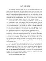
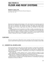
FIGURE 14.1
NEW RIVER GORGE BRIDGE
LOCATION: Fayetteville, West Virginia
TYPE: Trussed deck arch, 40 panels, 36 at 40
ע
to 43
ע
ft
SPAN: 1,700 ft RISE: 353 ft RISE / SPAN
ϭ
1:4.8
NO. OF LANES OF TRAFFIC: 4
HINGES: 2 CROWN DEPTH: 34 ft DEPTH / SPAN
ϭ
1:50
AVERAGE DEAD LOAD: LB PER FT
Deck slab and surfacing of roadway ................................... 8,600
Railings and parapets ............................................... 1,480
Floor steel for roadway .............................................. 3,560
Arch trusses ....................................................... 11,180
Arch bracing ...................................................... 1,010
Arch bents and bracing .............................................. 2,870
TOTAL ........................................................... 28,700
SPECIFICATION FOR LIVE LOADING: H520-44
EQUIVALENT LIVE
ϩ
IMPACT LOADING PER ARCH FOR FULLY LOADED
STRUCTURE: 1,126 lb per ft
TYPES OF STEEL IN STRUCTURE:
Arch ................................................................... A588
Floor system ............................................................ A588
OWNER: State of West Virginia
ENGINEER: Michael Baker, Jr., Inc.
FABRICATOR/ ERECTOR: American Bridge Division, U.S. Steel Corporation
DATE OF COMPLETION: October, 1977
ARCH BRIDGES
14.13
FIGURE 14.2 Details of New River Gorge Bridge.
14.14
SECTION FOURTEEN
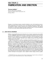
FIGURE 14.3
BAYONNE BRIDGE
LOCATION: Between Bayonne, N.J., and Port Richmond, Staten Island, N.Y.
TYPE: Half-through truss arch, 40 panels at 41.3 ft
SPAN: 1,675 ft RISE: 266 ft RISE / SPAN
ϭ
1:6.3
NO. OF LANES OF TRAFFIC: 4 plus 2 future rapid transit
HINGES: 2 CROWN DEPTH: 37.5 FT DEPTH / SPAN
ϭ
1:45
AVERAGE DEAD LOAD: LB PER FT
Track, paving ....................................................... 6,340
Floor steel and floor bracing ........................................... 6,160
Arch truss and bracing ............................................... 14,760
Arch hangers ....................................................... 540
Miscellaneous ...................................................... 200
TOTAL ............................................................ 28,000
SPECIFICATION LIVE LOADING: LB PER FT
2 rapid-transit lines at 6,000 lb per ft ................................... 12,000
4 roadway lanes at 2,500 lb per ft ...................................... 10,000
2 sidewalks at 600 lb ................................................ 1,200
TOTAL (unreduced) ................................................... 23,200
EQUIVALENT LIVE
ϩ
IMPACT LOADING ON EACH ARCH FOR FULLY LOADED
STRUCTURE WITH REDUCTION FOR MULTIPLE LANES AND LENGTH OF LOADING:
2,800 lb per lin ft
TYPES OF STEEL IN STRUCTURE: About 50% carbon steel, 30% silicon steel, and 20% high-
alloy steel (carbon-manganese)
OWNER: The Port Authority of New York and New Jersey
ENGINEER: O. H. Ammann, Chief Engineer
FABRICATOR: American Bridge Co., U.S. Steel Corp. (also erector)
DATE OF COMPLETION: 1931
ARCH BRIDGES
14.15
FIGURE 14.4 Details of Bayonne Bridge.
14.16
SECTION FOURTEEN
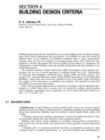
FIGURE 14.5
FREMONT BRIDGE
LOCATION: Portland, Oregon
TYPE: Half-through, tied, solid ribbed arch, 28 panels at 44.83 ft
SPAN: 1,255 ft RISE: 341 ft RISE / SPAN
ϭ
1:3.7
NO. OF LANES OF TRAFFIC: 4 each upper and lower roadways
HINGES: 2 DEPTH: 4 ft DEPTH / SPAN
ϭ
1:314
AVERAGE DEAD LOAD: LB PER FT
Decks and surfacing .......................................... 10,970
Railings and Parapets ......................................... 1,280
Floor steel for roadway ....................................... 4,000
Floor bracing ............................................... 765
Arch ribs ................................................... 2,960
Arch bracing ................................................ 1,410
Arch hangers or columns and bracing ........................... 1,250
Arch tie girders ............................................. 4,200
TOTAL .................................................... 26,835
SPECIFICATION FOR LIVE LOADING: AASHTO HS20-44
EQUIVALENT LIVE
ϩ
IMPACT LOADING FOR ARCH FOR FULLY LOADED
STRUCTURE: 2,510 lb per ft
TYPES OF STEEL IN STRUCTURE:
Arch ribs and tie girders .................................. A514, A588, A441, A36
Floor system .................................................. A588, A441, A36
OWNER: State of Oregon, Department of Transportation
ENGINEER: Parson, Brinckerhoff, Quade & Douglas
FABRICATOR: American Bridge Division, U.S. Steel Corp.
ERECTOR: Murphy Pacific Corporation
DATE OF COMPLETION: 1973
ARCH BRIDGES
14.17
FIGURE 14.6 Details of Fremont Bridge.
14.18
SECTION FOURTEEN
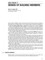
FIGURE 14.7
ROOSEVELT LAKE BRIDGE
LOCATION: Roosevelt, Arizona, SR 188
TYPE: Half through, solid rib arch, 16 panels at 50 ft
SPAN: 1,080 ft RISE: 230 ft RISE / SPAN
ϭ
1:4.7
NO. OF LANES OF TRAFFIC: 2
HINGES: 0 CROWN DEPTH: 8 ft DEPTH / SPAN
ϭ
1:135
AVERAGE DEAD LOAD: LB PER FT
Deck slab, and surfacing of roadway ..................................... 4,020
Railings and parapets ................................................. 800
Floor steel for roadway ................................................ 1,140
Floor bracing ........................................................ 190
Arch ribs ........................................................... 4,220
Arch bracing ........................................................ 790
Arch hangers ........................................................ 80
TOTAL............................................................. 11,240
SPECIFICATION FOR LIVE LOADING: HS20-44
EQUIVALENT LIVE
ϩ
IMPACT LOADING PER ARCH FOR FULLY LOADED STRUCTURE:
971 lb per ft
TYPES OF STEEL IN STRUCTURE:
Arch ribs and ties ......................................................... A572
Hanger floorbeams and stringers ............................................. A572
All others ............................................................... A36
OWNER: Arizona Department of Transportation
ENGINEER: Howard Needles Tammen and Bergendoff
CONTRACTOR: Edward Kraemer & Sons, Inc.
FABRICATOR: Pittsburgh DesMoines Steel Co. / Schuff Steel
ERECTOR: John F. Beasley Construction Co.
DATE OF COMPLETION: October 23, 1991 Public Opening
ARCH BRIDGES
14.19
FIGURE 14.8 Details of Roosevelt Lake Bridge.
14.20
SECTION FOURTEEN
FIGURE 14.9
LEWISTON–QUEENSTON BRIDGE
LOCATION: Over the Niagara River between Lewiston, N.Y., and Queenston, Ontario
TYPE: Solid-ribbed deck arch, 23 panels at 41.6 ft
SPAN: 1,000 ft RISE: 159 ft RISE / SPAN
ϭ
1:6.3
NO. OF LANES OF TRAFFIC: 4
HINGES: 0 DEPTH: 13.54 ft DEPTH / SPAN
ϭ
1:74
AVERAGE DEAD LOAD: LB PER FT
Deck slab and surfacing for roadway .................................... 5,700
Slabs for sidewalks ................................................... 495
Railings and parapets ................................................. 780
Floor steel for roadway and sidewalks ................................... 2,450
Floor bracing ........................................................ 110
Arch ribs ........................................................... 7,085
Arch bracing ........................................................ 1,060
Miscellaneous—utilities, excess, etc. ..................................... 300
TOTAL ............................................................ 19,370
SPECIFICATION LIVE LOADING: HS20-S16-44
EQUIVALENT LIVE
ϩ
IMPACT LOADING ON EACH ARCH FOR FULLY LOADED
STRUCTURE: 1,357 lb per ft
TYPES OF STEEL IN STRUCTURE: %
Arch ribs .................................................. A440 100
Spandrel columns ........................................... A7 94
A440 6
Rib bracing and end towers ................................... A7 100
Floor system ...................................................... A373 and A7
OWNER: Niagara Falls Bridge Commission
ENGINEER: Hardesty & Hanover
FABRICATOR: Bethlehem Steel Co. and Dominion Steel and Coal Corp., Ltd., Subcontractor
DATE OF COMPLETION: Nov. 1, 1962
ARCH BRIDGES
14.21
FIGURE 14.10 Details of Lewiston–Queenston Bridge.
14.22
SECTION FOURTEEN
FIGURE 14.11
SHEARMAN MINTON BRIDGE
LOCATION: On Interstate 64 over the Ohio River between Louisville, Ky., and New Albany, Ind.
TYPE: Tied, through, truss arch, 22 panels at 36.25 ft
SPAN: 800 ft RISE: 140 ft RISE / SPAN
ϭ
1:5.7
NO. OF LANES OF TRAFFIC: 6, double deck
HINGES: 2 CROWN DEPTH: 30 ft DEPTH / SPAN
ϭ
1:27
AVERAGE DEAD LOAD: LB PER FT
Deck slab and surfacing for roadway ................................... 7,600
Slabs for sidewalks ................................................. 1,656
Railings and parapets ............................................... 804
Floor steel for roadway and sidewalks ................................. 2,380
Floor bracing ...................................................... 420
Arch trusses ...................................................... 3,400
Arch bracing ...................................................... 880
Arch hangers and bracing ........................................... 160
Arch ties ......................................................... 1,040
Miscellaneous—utilities, excess, etc. (including future searing surface) ....... 1,680
TOTAL .......................................................... 20,020
SPECIFICATION LIVE LOADING: H20-S16
EQUIVALENT LIVE
ϩ
IMPACT LOADING ON EACH ARCH FOR FULLY LOADED STRUC-
TURE: 1,755 LB PER FT
TYPES OF STEEL IN STRUCTURE: %
Arch trusses ....................................................... A514 69
A242 18
A373 13
Floor system ....................................................... A242 36
A7 62
A373 2
OWNER: Indiana Department of Transportation and Kentucky Transportation Cabinet
ENGINEER: Hazelet & Erdal, Louisville, Ky.
FABRICATOR: R. C. Mahon Co.
DATE OF COMPLETION: Dec. 22, 1961, opened to traffic
ARCH BRIDGES
14.23
FIGURE 14.12 Details of Sherman Minton Bridge.
14.24
SECTION FOURTEEN
FIGURE 14.13
WEST END–NORTH SIDE BRIDGE
LOCATION: Pittsburgh, Pennsylvania, over Ohio River
TYPE: Tied, through, truss arch, 28 panels at 27.8 ft
SPAN: 778 ft RISE: 151 ft RISE / SPAN
ϭ
1:5.2
NO. OF LANES OF TRAFFIC: 4, including 2 street-railway tracks
HINGES: Two CROWN DEPTH: 25 DEPTH/ SPAN
ϭ
1:31
AVERAGE DEAD LOAD: LB PER FT
Roadway, sidewalks, and railings ...................................... 4,870
Floor steel and floor bracing ......................................... 2,360
Arch trusses ....................................................... 4,300
Arch ties ......................................................... 2,100
Arch bracing ...................................................... 550
Hangers .......................................................... 360
Utilities and excess ................................................. 600
TOTAL ........................................................... 15,140
SPECIFICATION LIVE LOADING: Allegheny County Truck & Street Car
EQUIVALENT LIVE
ϩ
IMPACT LOADING ON EACH ARCH FOR FULLY LOADED
STRUCTURE: 1,790 lb per ft
TYPES OF STEEL IN STRUCTURE:
All main material in arch trusses and ties including splice material—silicon steel.
Floor system and bracing ............................................ A7
Hangers .......................................................... Wire rope
OWNER: Pennsylvania Department of Transportation
ENGINEER: Department of Public Works, Allegheny County
FABRICATOR: American Bridge Division, U.S. Steel Corp.
DATE OF COMPLETION: 1932
ARCH BRIDGES
14.25
FIGURE 14.14 Details of West End–North Side Bridge.