Sổ tay kết cấu thép - Section 15
Bạn đang xem bản rút gọn của tài liệu. Xem và tải ngay bản đầy đủ của tài liệu tại đây (1.19 MB, 100 trang )
15.1
SECTION 15
CABLE-SUSPENDED BRIDGES
Walter Podolny, Jr., P.E.
Senior Structural Engineer, Office of Bridge Technology,
Federal Highway Administration,
U.S. Department of Transportation, Washington, D.C.
Few structures are as universally appealing as cable-supported bridges. The origin of the
concept of bridging large spans with cables, exerting their strength in tension, is lost in
antiquity and undoubtedly dates back to a time before recorded history. Perhaps primitive
humans, wanting to cross natural obstructions such as deep gorges and large streams, ob-
served a spider spinning a web or monkeys traveling along hanging vines.
15.1 EVOLUTION OF CABLE-SUSPENDED BRIDGES
Early cable-suspended bridges were footbridges consisting of cables formed from twisted
vines or hide drawn tightly to reduce sag. The cable ends were attached to trees or other
permanent objects located on the banks of rivers or at the edges of gorges or other natural
obstructions to travel. The deck, probably of rough-hewn plank, was laid directly on the
cable. This type of construction was used in remote ages in China, Japan, India, and Tibet.
It was used by the Aztecs of Mexico, the Incas of Peru, and by natives in other parts of
South America. It can still be found in remote areas of the world.
From the sixteenth to nineteenth centuries, military engineers made effective use of rope
suspension bridges. In 1734, the Saxon army built an iron-chain bridge over the Oder River
at Glorywitz, reportedly the first use in Europe of a bridge with a metal suspension system.
However, iron chains were used much earlier in China. The first metal suspension bridge in
North America was the Jacob’s Creek Bridge in Pennsylvania, designed and erected by James
Finley in 1801. Supported by two suspended chains of wrought-iron links, its 70-ft span was
stiffened by substantial trussed railing and timber planks.
Chains and flat wrought-iron bars dominated suspension-bridge construction for some
time after that. Construction of this type was used by Thomas Telford in 1826 for the noted
Menai Straits Bridge, with a main span of 580 ft. But 10 years before, in 1816, the first
wire suspension bridges were built, one at Galashiels, Scotland, and a second over the
Schuylkill River in Philadelphia.
A major milestone in progress with wire cable was passed with erection of the 1,010-ft
suspended span of the Ohio River Bridge at Wheeling, Va. (later W.Va.), by Charles Ellet,
Jr., in 1849. A second important milestone was the opening in 1883 of the 1,595.5-ft wire-
cable-supported span of the Brooklyn Bridge, built by the Roeblings.
15.2
SECTION FIFTEEN
In 1607, a Venetian engineer named Faustus Verantius published a description of a sus-
pended bridge partly supported with several diagonal chain stays (Fig. 15.1a ). The stays in
that case were used in combination with a main supporting suspension (catenary) cable. The
first use of a pure stayed bridge is credited to Lo¨scher, who built a timber-stayed bridge in
1784 with a span of 105 ft (Fig. 15.2a ). The pure-stayed-bridge concept was apparently not
used again until 1817 when two British engineers, Redpath and Brown, constructed the
King’s Meadow Footbridge (Fig. 15.1b ) with a span of about 110 ft. This structure utilized
sloping wire cable stays attached to cast-iron towers. In 1821, the French architect, Poyet,
suggested a pure cable-stayed bridge (Fig. 15.2b ) using bar stays suspended from high
towers.
The pure cable-stayed bridge might have become a conventional form of bridge construc-
tion had it not been for an unfortunate series of circumstances. In 1818, a composite sus-
pension and stayed pedestrian bridge crossing the Tweed River near Dryburgh-Abbey, Eng-
land (Fig. 15.1c) collapsed as a result of wind action. In 1824, a cable-stayed bridge crossing
the Saale River near Nienburg, Germany (Fig. 15.1d ) collapsed, presumably from overload-
ing. The famous French engineer C. L. M. H. Navier published in 1823 a prestigious work
wherein his adverse comments on the failures of several cable-stayed bridges virtually con-
demned the use of cable stays to obscurity.
Despite Navier’s adverse criticism of stayed bridges, a few more were built shortly after
the fatal collapses of the bridges in England and Germany, for example, the Gischlard-
Arnodin cable bridge (Fig. 15.2c ) with multiple sloping cables hung from two masonry
towers. In 1840, Hatley, an Englishman, used chain stays in a parallel configuration resem-
bling harp strings (Fig. 15.2d). He maintained the parallel spacing of the main stays by using
a closely spaced subsystem anchored to the deck and perpendicular to the principal load-
carrying cables.
The principle of using stays to support a bridge superstructure did not die completely in
the minds of engineers. John Roebling incorporated the concept in his suspension bridges,
such as his Niagara Falls Bridge (Fig. 15.3); the Old St. Clair Bridge in Pittsburgh (Fig.
15.4); the Cincinnati Bridge across the Ohio River, and the Brooklyn Bridge in New York.
The stays were used in addition to vertical suspenders to support the bridge superstructure.
Observations of performance indicated that the stays and suspenders were not efficient part-
ners. Consequently, although the stays were comforting safety measures in the early bridges,
in the later development of conventional catenary suspension bridges the stays were omitted.
The conventional suspension bridge was dominant until the latter half of the twentieth cen-
tury.
The virtual banishment of stayed bridges during the nineteenth and early twentieth cen-
turies can be attributed to the lack of sound theoretical analyses for determination of the
internal forces of the total system. The failure to understand the behavior of the stayed system
and the lack of methods for controlling the equilibrium and compatibility of the various
highly indeterminate structural components appear to have been the major drawback to fur-
ther development of the concept. Furthermore, the materials of the period were not suitable
for stayed bridges.
Rebirth of stayed bridges appears to have begun in 1938 with the work of the German
engineer Franz Dischinger. While designing a suspension bridge to cross the Elbe River near
Hamburg (Fig. 15.5), Dischinger determined that the vertical deflection of the bridge under
railroad loading could be reduced considerably by incorporating cable stays in the suspension
system. From these studies and his later design of the Stro¨msund Bridge in Sweden (1955)
evolved the modern cable-stayed bridge. However, the biggest impetus for cable-stayed
bridges came in Germany after World War II with the design and construction of bridges to
replace those that had been destroyed in the conflict.
(W. Podolny, Jr., and J. B. Scalzi, ‘‘Construction and Design of Cable-Stayed Bridges,’’
2d ed., John Wiley & Sons, Inc., New York; R. Walther et al., ‘‘Cable-Stayed Bridges,’’
Thomas Telford, London; D. P. Billington and A. Nazmy, ‘‘History and Aesthetics of Cable-
Stayed Bridges,’’ Journal of Structural Engineering, vol. 117, no. 10, October 1990, Amer-
ican Society of Civil Engineers.)
CABLE-SUSPENDED BRIDGES
15.3
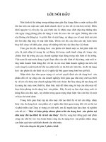
FIGURE 15.1 (a) Chain bridge by Faustus Verantius, 1607. (b) King’s Meadow Footbridge. (c)
Dryburgh-Abbey Bridge. (d ) Nienburg Bridge. (Reprinted with permission from K. Roik et al.
‘‘Schra¨gseilbru¨chen,’’ Wilhelm Ernst & Sohn, Berlin.)
15.4
SECTION FIFTEEN
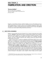
FIGURE 15.2 (a)Lo¨scher-type timber bridge. (b) Poyet-type bridge. (c) Gischlard-Arnodin-type
sloping-cable bridge. (d ) Hatley chain bridge. (Reprinted with permission from H. Thul, ‘‘Cable-Stayed
Bridges in Germany,’’ Proceedings of the Conference on Structural Steelwork, 1966. The British
Constructional Steelwork Association, Ltd., London.)
CABLE-SUSPENDED BRIDGES
15.5
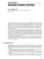
FIGURE 15.3 Niagara Falls Bridge.
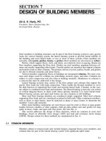
FIGURE 15.4 Old St. Clair Bridge, Pittsburgh.
15.2 CLASSIFICATION OF CABLE-SUSPENDED BRIDGES
Cable-suspended bridges that rely on very high strength steel cables as major structural
elements may be classified as suspension bridges or cable-stayed bridges. The fundamental
difference between these two classes is the manner in which the bridge deck is supported
by the cables. In suspension bridges, the deck is supported at relatively short intervals by
15.6
SECTION FIFTEEN
FIGURE 15.5 Bridge system proposed by Dischinger. (Reprinted with permission from F. Dis-
chinger, ‘‘Hangebru¨chen for Schwerste Verkehrslasten,’’ Der Bauingenieur, Heft 3 and 4, 1949.)
FIGURE 15.6 Cable-suspended bridge systems: (a) suspension and (b) cable-stayed. (Reprinted
with permission from W. Podolny, Jr. and J. B. Scalzi, ‘‘Construction and Design of Cable-Stayed
Bridges,’’ 2d ed., John Wiley & Sons, Inc., New York.)
vertical suspenders, which, in turn, are supported from a main cable (Fig. 15.6a ). The main
cables are relatively flexible and thus take a profile shape that is a function of the magnitude
and position of loading. Inclined cables of the cable-stayed bridge (Fig. 15.6b ), support the
bridge deck directly with relatively taut cables, which, compared to the classical suspension
bridge, provide relatively inflexible supports at several points along the span. The nearly
linear geometry of the cables produces a bridge with greater stiffness than the corresponding
suspension bridge.
Cable-suspended bridges are generally characterized by economy, lightness, and clarity
of structural action. These types of structures illustrate the concept of form following function
and present graceful and esthetically pleasing appearance. Each of these types of cable-
suspended bridges may be further subclassified; those subclassifications are presented in
articles that follow.
Many early cable-suspended bridges were a combination of the suspension and cable-
stayed systems (Art. 15.1). Such combinations can offer even greater resistance to dynamic
loadings and may be more efficient for very long spans than either type alone. The only
contemporary bridge of this type is Steinman’s design for the Salazar Bridge across the
Tagus River in Portugal. The present structure, a conventional suspension bridge, is indicated
in Fig. 15.7a In the future, cable stays are to be installed to accommodate additional rail
traffic (Fig. 15.7b ).
CABLE-SUSPENDED BRIDGES
15.7
FIGURE 15.7 The Salazar Bridge. (a) elevation of the bridge in 1993; (b) elevation of future
bridge. (Reprinted with permission from W. Podolny, Jr., and J. B. Scalzi, ‘‘Construction and Design
of Cable-Stayed Bridges,’’ John Wiley & Sons, Inc., New York.)
(W. Podolny, Jr., and J. B. Scalzi, ‘‘Construction and Design of Cable-Stayed Bridges,’’
2nd ed., John Wiley & Sons, Inc., New York.)
15.3 CLASSIFICATION AND CHARACTERISTICS OF SUSPENSION
BRIDGES
Suspension bridges with cables made of high-strength, zinc-coated, steel wires are suitable
for the longest of spans. Such bridges usually become economical for spans in excess of
1000 ft, depending on specific site constraints. Nevertheless, many suspension bridges with
spans as short as 300 or 400 ft have been built, to take advantage of their esthetic features.
The basic economic characteristic of suspension bridges, resulting from use of high-
strength materials in tension, is lightness, due to relatively low dead load. But this, in turn,
carries with it the structural penalty of flexibility, which can lead to large deflections under
live load and susceptibility to vibrations. As a result, suspension bridges are more suitable
for highway bridges than for the more heavily loaded railroad bridges. Nevertheless, for
either highway or railroad bridges, care must be taken in design to provide resistance to
wind- or seismic-induced oscillations, such as those that caused collapse of the first Tacoma
Narrows Bridge in 1940.
15.3.1 Main Components of Suspension Bridges
A pure suspension bridge is one without supplementary stay cables and in which the main
cables are anchored externally to anchorages on the ground. The main components of a
suspension bridge are illustrated in Fig. 15.8. Most suspension bridges are stiffened; that is,
as shown in Fig. 15.8, they utilize horizontal stiffening trusses or girders. Their function is
to equalize deflections due to concentrated live loads and distribute these loads to one or
more main cables. The stiffer these trusses or girders are, relative to the stiffness of the
cables, the better this function is achieved. (Cables derive stiffness not only from their cross-
sectional dimensions but also from their shape between supports, which depends on both
cable tension and loading.)
For heavy, very long suspension spans, live-load deflections may be small enough that
stiffening trusses would not be needed. When such members are omitted, the structure is an
unstiffened suspension bridge. Thus, if the ratio of live load to dead load were, say, 1
Ϻ
4, the
midspan deflection would be of the order of
1
⁄
100
of the sag, or 1/ 1,000 of the span, and the
15.8
SECTION FIFTEEN
FIGURE 15.8 Main components of a suspension bridge.
FIGURE 15.9 Suspension-bridge arrangements. (a) One suspended span, with pin-ended stiffening
truss. (b) Three suspended spans, with pin-ended stiffening trusses. (c) Three suspended spans, with
continuous stiffening truss. (d ) Multispan bridge, with pin-ended stiffening trusses. (e) Self-anchored
suspension bridge.
use of stiffening trusses would ordinarily be unnecessary. (For the George Washington Bridge
as initially constructed, the ratio of live load to dead load was approximately 1
Ϻ
6. Therefore,
it did not need a stiffening truss.)
15.3.2 Types of Suspension Bridges
Several arrangements of suspension bridges are illustrated in Fig. 15.9. The main cable is
continuous, over saddles at the pylons, or towers, from anchorage to anchorage. When the
main cable in the side spans does not support the bridge deck (side spans independently
supported by piers), that portion of the cable from the saddle to the anchorage is virtually
straight and is referred to as a straight backstay. This is also true in the case shown in Fig.
15.9a where there are no side spans.
Figure 15.9d represents a multispan bridge. This type is not considered efficient, because
its flexibility distributes an undesirable portion of the load onto the stiffening trusses and
may make horizontal ties necessary at the tops of the pylons. Ties were used on several
French multispan suspension bridges of the nineteenth century. However, it is doubtful
whether tied towers would be esthetically acceptable to the general public. Another approach
to multispan suspension bridges is that used for the San Francisco–Oakland Bay Bridge (Fig.
CABLE-SUSPENDED BRIDGES
15.9
FIGURE 15.10 San Francisco-Oakland Bay Bridge.
FIGURE 15.11 Bridge over the Rhine at Ruhrort-Homberg, Germany, a bridle-chord type.
15.10). It is essentially composed of two three-span suspension bridges placed end to end.
This system has the disadvantage of requiring three piers in the central portion of the struc-
ture where water depths are likely to be a maximum.
Suspension bridges may also be classified by type of cable anchorage, external or internal.
Most suspension bridges are externally anchored (earth-anchored) to a massive external
anchorage (Fig. 15.9a to d). In some bridges, however, the ends of the main cables of a
suspension bridge are attached to the stiffening trusses, as a result of which the structure
becomes self-anchored (Fig. 15.9e ). It does not require external anchorages.
The stiffening trusses of a self-anchored bridge must be designed to take the compression
induced by the cables. The cables are attached to the stiffening trusses over a support that
resists the vertical component of cable tension. The vertical upward component may relieve
or even exceed the dead-load reaction at the end support. If a net uplift occurs, a pendulum-
link tie-down should be provided at the end support.
Self-anchored suspension bridges are suitable for short to moderate spans (400 to 1,000
ft) where foundation conditions do not permit external anchorages. Such conditions include
poor foundation-bearing strata and loss of weight due to anchorage submergence. Typical
examples of self-anchored suspension bridges are the Paseo Bridge at Kansas City, with a
main span of 616 ft, and the former Cologne-Mu¨lheim Bridge (1929) with a 1,033-ft span.
Another type of suspension bridge is referred to as a bridle-chord bridge. Called by
Germans Zu¨gelgurtbru¨cke, these structures are typified by the bridge over the Rhine River
at Ruhrort-Homberg (Fig. 15.11), erected in 1953, and the one at Krefeld-Urdingen, erected
in 1950. It is a special class of bridge, intermediate between the suspension and cable-stayed
types and having some of the characteristics of both. The main cables are curved but not
continuous between towers. Each cable extends from the tower to a span, as in a cable-
stayed bridge. The span, however, also is suspended from the cables at relatively short
intervals over the length of the cables, as in suspension bridges.
A distinction to be made between some early suspension bridges and modern suspension
bridges involves the position of the main cables in profile at midspan with respect to the
stiffening trusses. In early suspension bridges, the bottom of the main cables at maximum
sag penetrated the top chord of the stiffening trusses and continued down to the bottom
chord (Fig. 15.5, for example). Because of the design theory available at the time, the depth
of the stiffening trusses was relatively large, as much as
1
⁄
40
of the span. Inasmuch as the
height of the pylons is determined by the sag of the cables and clearance required under the
stiffening trusses, moving the midspan location of the cables from the bottom chord to the
15.10
SECTION FIFTEEN
FIGURE 15.12 Suspension system with inclined suspenders.
top chord increases the pylon height by the depth of the stiffening trusses. In modern sus-
pension bridges, stiffening trusses are much shallower than those used in earlier bridges and
the increase in pylon height due to midspan location of the cables is not substantial (as
compared with the effect in the Williamsburg Bridge in New York City where the depth of
the stiffening trusses is 25% of the main-cable sag).
Although most suspension bridges employ vertical suspender cables to support the stiff-
ening trusses or the deck structural framing directly (Fig. 15.8), a few suspension bridges,
for example, the Severn Bridge in England and the Bosporus Bridge in Turkey, have inclined
or diagonal suspenders (Fig. 15.12). In the vertical-suspender system, the main cables are
incapable of resisting shears resulting from external loading. Instead, the shears are resisted
by the stiffening girders or by displacement of the main cables. In bridges with inclined
suspenders, however, a truss action is developed, enabling the suspenders to resist shear.
(Since the cables can support loads only in tension, design of such bridges should ensure
that there always is a residual tension in the suspenders; that is, the magnitude of the com-
pression generated by live-load shears should be less than the dead-load tension.) A further
advantage of the inclined suspenders is the damping properties of the system with respect
to aerodynamic oscillations.
(N. J. Gimsing, ‘‘Cable-Supported Bridges—Concept and Design,’’ John Wiley & Sons,
Inc., New York.)
15.3.3 Suspension Bridge Cross Sections
Figure 15.13 shows typical cross sections of suspension bridges. The bridges illustrated in
Fig. 15.13a, b, and c have stiffening trusses, and the bridge in Fig. 15.13d has a steel box-
girder deck. Use of plate-girder stiffening systems, forming an H-section deck with horizontal
web, was largely superseded after the Tacoma Narrows Bridge failure by truss and box-
girder stiffening systems for long-span bridges. The H deck, however, is suitable for short
spans.
The Verrazano Narrows Bridge (Fig. 15.13a), employs 6-in-deep, concrete-filled, steel-
grid flooring on steel stringers to achieve strength, stiffness, durability, and lightness. The
double-deck structure has top and bottom lateral trusses. These, together with the transverse
beams, stringers, cross frames, and stiffening trusses, are conceived to act as a tube resisting
vertical, lateral, and torsional forces. The cross frames are rigid frames with a vertical mem-
ber in the center.
The Mackinac Bridge (Fig. 15.13b ) employs a 4
1
⁄
4
-in. steel-grid flooring. The outer two
lanes were filled with lightweight concrete and topped with bituminous-concrete surfacing.
The inner two lanes were left open for aerodynamic venting and to reduce weight. The single
deck is supported by stiffening trusses with top and bottom lateral bracing as well as ample
cross bracing.
The Triborough Bridge (Fig. 15.13c ) has a reinforced-concrete deck carried by floorbeams
supported at the lower panel points of through stiffening trusses.
CABLE-SUSPENDED BRIDGES
15.11
FIGURE 15.13 Typical cross sections of suspension bridges: (a) Verrazano Narrows,
(b) Mackinac, (c) Triborough, (d ) Severn.
15.12
SECTION FIFTEEN
FIGURE 15.14 Suspension-bridge pylons: (a) Golden Gate, (b) Mackinac, (c)
San Francisco-Oakland Bay, (d) First Tacoma Narrows, (e) Walt Whitman.
The Severn Bridge (Fig. 15.13d) employs a 10-ft-deep torsion-resisting box girder to
support an orthotropic-plate deck. The deck plate is stiffened by steel trough shapes, and the
remaining plates, by flat-bulb stiffeners. The box was faired to achieve the best aerodynamic
characteristics.
15.3.4 Suspension Bridge Pylons
Typical pylon configurations, shown in Fig. 15.14, are portal frames. For economy, pylons
should have the minimum width in the direction of the span consistent with stability but
sufficient width at the top to take the cable saddle.
Most suspension bridges have cables fixed at the top of the pylons. With this arrangement,
because of the comparative slenderness of pylons, top deflections do not produce large
stresses. It is possible to use rocker pylons, pinned at the base and top, but they are restricted
to use with short spans. Also, pylons fixed at the base and with roller saddles at the top are
possible, but limited to use with medium spans. The pylon legs may, in any event, be tapered
to allow for the decrease in area required toward the top.
The statical action of the pylon and the design of details depend on the end conditions.
Simply supported, main-span stiffening trusses are frequently suspended from the pylons
on short pendulum hangers. Dependence is placed primarily on the short center-span sus-
penders to keep the trusses centered. In this way, temperature effects on the pylon can be
reduced by half.
A list of major modern suspension bridges is provided in Table 15.1.
CABLE-SUSPENDED BRIDGES
15.13
TABLE 15.1
Major Suspension Bridges
Name Location
Length of
main span
ft. m
Year
completed
Akashi Kaiko Japan 6529 1990 1998
Storebelt Zealand-Sprago, Denmark 5328 1624 1997
Humber River Hull, England 4626 1410 1981
Jiangyin Bridge Yangtze R., Jiangsu Prov., China 4544 1385
Tsing Ma Bridge Hong Kong 4518 1377 1997
Hardanger Fjord Norway 4347 1325
Verranzano-Narrows New York, NY, USA 4260 1298 1964
Golden Gate San Francisco, USA 4200 1280 1937
Ho¨ga Kusten 400 km N. Stockholm, Sweden 3970 1210 1997
Mackinac Straits Michigan, USA 3800 1158 1957
Minami Bisan-Seto Japan 3609 1100 1988
2nd Bosphorus Istanbul, Turkey 3576 1090 1988
1st Bosphorus Istanbul, Turkey 3524 1074 1973
George Washington New York, NY, USA 3500 1067 1931
3rd Kurushima Bridge
1
Japan 3379 1030 (1999)
2nd Kurushima Bridge
1
Japan 3346 1020 (1999)
Tagus River
2
Lisbon, Portugal 3323 1013 1966
Forth Road Queensferry, Scotland 3300 1006 1964
Kita Bisan-Seto Japan 3248 990 1988
Severn Beachley, England 3240 988 1966
Shimotsui Straits Japan 3084 940 1988
Xiling Bridge over Yangtze R., Xiling Gorge, China 2953 900 1996
Tigergate (Humen) Pearl R., Guangdon Prov., China 2913 888 1997
Ohnaruto Japan 2874 876 1985
Tacoma Narrows I
3
Tacoma, Washington, USA 2800 853 1940
Tacoma Narrows II Tacoma, Washington, USA 2800 853 1950
Askøy Near Bergen, Norway 2787 850 1992
Innoshima Japan 2526 770 1983
Akinada
1
Japan 2461 750
Hakucho
1
Japan 2362 720
Kanmon Straits Kyushu-Honshu, Japan 2336 712 1973
Angostura Ciudad Bolivar, Venezuela 2336 712 1967
San Francisco-Oakland Bay
4
San Francisco, California, USA 2310 704 1936
Bronx-Whitestone New York, NY, USA 2300 701 1939
Pierre Laporte Quebec, Canada 2190 668 1970
Delaware Memorial
5
Wilmington, DE, USA 2150 655 1951
1968
Seaway Skyway Ogdensburg, NY, USA 2150 655 1960
Gjemnessund Norway 2044 623 1992
Walt Whitman Philadelphia, PA, USA 2000 610 1957
Tancarville Tancarville, France 1995 608 1959
1st Kurushima Bridge
1
Japan 1969 600 (1999)
Lillebaelt Lillebaelt Strait, Denmark 1969 600 1970
Kvisti
1
Bergen, Hordland, Norway 1952 592
Tokyo Port Connect. Br. Tokyo, Japan 1870 570 1993
Ambassador Detroit, MI, USA-Canada 1850 564 1929
Skyway
3
(Chicago World’s Fair) USA 1850 564 1933
Hakata-Ohshima Japan 1837 560 1988
Throgs Neck New York, NY, USA 1800 549 1961
15.14
SECTION FIFTEEN
TABLE 15.1
Major Suspension Bridges (Continued )
Name Location
Length of
main span
ft. m
Year
completed
Benjamin Franklin
2
Philadelphia, PA, USA 1750 533 1926
Skjomen Narvik, Norway 1722 525 1972
Kvalsund Hammerfest, Norway 1722 525 1977
Dazi Bridge Lasa, Xizang Region, China 1640 500 1984
Kleve-Emmerich Emmerich, Germany 1640 500 1965
Bear Mountain Peckskill, NY, USA 1632 497 1924
Wm. Preston Lane, Jr.
5
near Annapolis, MD, USA 1600 488 1952
Williamsburg
2
New York, NY, USA 1600 488 1903
Newport Newport, RI, USA 1600 488 1969
Chesapeake Bay Sandy Point, MD, USA 1600 488 1952
Brooklyn
7
New York, NY, USA 1595 486 1883
Lions Gate Vancouver, B.C., Canada 1550 472 1939
Hirato Ohashi Hirato, Japan 1536 468 1977
Sotra Bergen, Norway 1535 468 1971
Hirato Japan 1526 465 1977
Vincent Thomas San Pedro-Terminal Is., CA, USA 1500 457 1963
Mid-Hudson Poughkeepsie, NY, USA 1495 457 1930
Shantou Bay Bridge Shantou, Guangdong Prov., China 1483 452 1995
Manhattan
2
New York, NY, USA 1470 448 1909
MacDonald Bridge Halifax, Nova Scotia, Canada 1447 441 1955
A. Murray Mackay Halifax, Nova Scotia, Canada 1400 426 1970
Triborough New York, NY, USA 1380 421 1936
Alvsborg Goteburg, Sweden 1370 418 1966
Hadong-Namhae Pusan, South Korea 1325 404 1973
Aquitaine Bordeaux, France 1292 394
Baclan Garrone R., Bordeaux, France 1292 394 1967
Ame-Darja R. Buhara-Ural, Russia 1280 390 1964
Clifton
3
Niagara Falls, NY, USA 1268 386 1869
Cologne-Rodenkirchen I
3
Cologne, Germany 1240 378 1941
Cologne-Rodenkirchen II
10
Cologne, Germany 1240 378 1955
St. Johns Portland, OR, USA 1207 368 1931
Wakato Kita-Kyushu City, Japan 1205 367 1962
Mount Hope Bristol, RI, USA 1200 366 1929
St Lawrence R., Ogdensburg, NY–Prescot, Ont. 1150 351 1960
Ponte Hercilio
2,6
Florianapolis, Brazil 1114 340 1926
Bidwell Bar Bridge Oroville, CA, USA 1108 338 1965
Middle Fork Feather R. California, USA 1105 337 1964
Varodd, Topdalsfjord Kristiansand, Norway 1105 337 1956
Tamar Road Plymouth, Great Britain 1100 335 1961
Deer Isle Deer Isle, ME, USA 1080 329 1939
Rombaks Narvik, Nordland, Norway 1066 325 1964
Maysville Maysville, KY, USA 1060 323 1931
Ile d’Orleans St. Lawrence R., Quebec, Canada 1059 323 1936
Ohio River Cincinnati, OH, USA 1057 322 1867
Otto Beit Zambezi R., Rodesia 1050 320 1939
Dent N. Fork, Clearwater R., ID, USA 1050 320 1971
Niagra
3
Lewiston, NY, USA 1040 317 1850
Cologne-Mulheim I
3
Cologne, Germany 1033 315 1929
Cologne-Mulheim II Cologne, Germany 1033 315 1951
CABLE-SUSPENDED BRIDGES
15.15
TABLE 15.1
Major Suspension Bridges (Continued )
Name Location
Length of
main span
ft. m
Year
completed
Miampimi Mexico 1030 314 1900
Wheeling West Virginia, USA 1010 308 1848
(Wheeling Bridge reconstructed after collapse) 1856
Yong Jong
1
Seoul, Korea 984 300 (2001)
Konohana
8,9
Osaka, Japan 984 300 1990
Elisabeth
6
Budapest, Hungary 951 290 1903
Tjeldsund Harstad, Norway 951 290 1967
Grand’ Mere Quebec, Canada 948 289 1929
Cauca River Columbia 940 287 1894
Jinhu Bridge Taining, Fujian Prov., China 932 284 1989
Peach River British Columbia, Canada 932 284 1950
Aramon France 902 275 1901
Cornwall-Masena St. Lawrence R., NY-Ontario 900 274 1958
Fribourg
3
Switzerland 896 273 1834
Brevik Telemark, Norway 892 272 1962
Royal George Arkansas R., Canon City, CO, USA 880 268 1929
Kjerringstraumen Nordland, Norway 853 260 1975
Vranov Lake Bridge Czech Republic 827 252 1993
Railway Bridge
3
Niagara River, NY, USA 821 250 1854
Dome, Grand Canyon Dome, AZ, USA 800 244 1929
Point
3,6
Pittsburgh, PA, USA 800 244 1877
Rochester Rochester, PA, USA 800 244 1896
Niagara River Lewiston, Nyn USA 800 244 1899
Thousand Is., Int. St. Lawrence R., USA-Canada 800 244 1938
Waldo Hancock Penobscot R., Bucksport, ME, USA 800 244 1931
Anthony Wayne Maumee R., Toledo, OH, USA 785 239 1931
Parkersburg Parkersburg, WV, USA 755 236 1916
Footbridge
3
Niagara R., NY, USA 770 235 1847
Vernaison France 764 233 1902
Cannes Ecluse France 760 232 1900
Ohio River E. Liverpool, OH, USA 750 229 1905
Gotteron Freiburg, Switzerland 746 227 1840
Iowa-Illinois Mem. I
3
Moline, IL, USA 740 226 1934
Iowa-Illinois Mem. II Moline, IL, USA 740 226 1959
Davenport Davenport, IL, USA 740 226 1935
Monongahela R. So. 10th St., Pittsburgh, PA, USA 725 221 1933
Rondout Kingston, NY, USA 705 215 1922
Ohio River E. Liverpool, OH, USA 705 215 1896
Clifton
3,6
Bristol, England 702 214 1864
Ohio River
6
St. Marys, OH, USA 700 213 1929
Ohio River
3,6
Point Pleasant, OH, USA 700 213 1928
Sixth Street Pittsburgh, PA, USA 700 213 1928
General U.S. Grant Ohio R., Portsmouth, OH, USA 700 213 1927
Airline St. JO, Texas, USA 700 213 1927
Red River Nocona, Texas, USA 700 213 1924
Ohio River Steubenville, OH, USA 700 213 1904
Ohio River Steubenville, OH, USA 689 210 1928
Isere Veurey, France 688 210 1934
Hungerford
3,6
London, England 676 206 1845
15.16
SECTION FIFTEEN
TABLE 15.1
Major Suspension Bridges (Continued )
Name Location
Length of
main span
ft. m
Year
completed
Mississippi R.
3
Minneapolis, MN, USA 675 206 1877
Meixihe Bridge Fengjie, Sichuan Prov., China 673 205 1990
Lancz
6
Budapest, Hungary 663 202 1845
White River Des Arc, Arkansas, USA 650 198 1928
Roche Bernard
3
Vilaine, France 650 198 1836
Missouri River Illinois, USA 643 196 1956
Caille
3
Annecy, France 635 194 1839
Columbia R. Beegee, WA, USA 632 193 1919
1
Under Construction.
2
Railroad & Highway.
3
Not Standing.
4
Twin Spans.
5
Twin Bridges.
6
Eyebar Chain.
7
Includes
cable stays.
8
Self-anchored.
10
Structure widened by addition of third cable. (1994)
15.4 CLASSIFICATION AND CHARACTERISTICS OF
CABLE-STAYED BRIDGES
The cable-stayed bridge has come into wide use since the 1950s for medium- and long-span
bridges, because of its economy, stiffness, esthetic qualities, and ease of erection without
falsework. Cable-stayed bridges utilize taut cables connecting pylons to a span to provide
intermediate support for the span. This principle has been understood by bridge engineers
for at least two centuries, as indicated in Art. 15.1.
Cable-stayed bridges are economical for bridge spans intermediate between those suited
for deck girders (usually up to 600 to 800 ft but requiring extreme depths, up to 33 ft) and
the longer-span suspension bridges (over 1,000 ft). The cable-stayed bridge, thus, finds ap-
plication in the general range of 600- to 1,600-ft spans, but spans as long as 2,600 ft may
be economically feasible.
A cable-stayed bridge has the advantage of greater stiffness over a suspension bridge.
Cable-stayed single or multiple box girders possess large torsional and lateral rigidity. These
factors make the structure stable against wind and aerodynamic effects.
15.4.1 Structural Characteristics of Cable-Stayed Bridges
The true action of a cable-stayed bridge is considerably different from that of a suspension
bridge. As contrasted with the relatively flexible main cables of the latter, the inclined, taut
cables of the cable-stayed structure furnish relatively stable point supports in the main span.
Deflections are thus reduced. The structure, in effect, becomes a continuous girder over the
piers, with additional intermediate, elastic (yet relatively stiff) supports in the span. As a
result, the stayed girder may be shallow. Depths usually range from
1
⁄
60
to
1
⁄
80
of the main
span, sometimes even as small as
1
⁄
100
of the span.
Cable forces are usually balanced between the main and flanking spans, and the structure
is internally anchored; that is, it requires no massive masonry anchorages. Second-order
effects of the type requiring analysis by a deflection theory are of relatively minor importance
for the common, self-anchored type of cable-stayed bridge, characterized by compression in
the main bridge girders.
CABLE-SUSPENDED BRIDGES
15.17
15.4.2 Types of Cable-Stayed Bridges
Cable-stayed bridges may be classified by the type of material they are constructed of, by
the number of spans stay-supported, by transverse arrangement of cable-stay planes, and by
the longitudinal stay geometry.
A concrete cable-stayed bridge has both the superstructure girder and the pylons con-
structed of concrete. Generally, the pylons are cast-in-place, although in some cases, the
pylons may be precast-concrete segments above the deck level to facilitate the erection
sequence. The girder may consist of either precast or cast-in-place concrete segments. Ex-
amples are the Talmadge Bridge in Georgia and the Sunshine Skyway Bridge in Florida.
All-steel cable-stayed bridges consist of structural steel pylons and one or more stayed
steel box girders with an orthotropic deck (Fig. 15.15). Examples are the Luling Bridge in
Louisiana and the Meridian Bridge in California (also constructed as a swing span).
Other so-called steel cable-stayed bridges are, in reality, composite structures with con-
crete pylons, structural-steel edge girders and floorbeams (and possibly stringers), and a
composite cast-in-place or precast plank deck. The precast deck concept is illustrated in Fig.
15.16.
In general, span arrangements are single span; two spans, symmetrical or asymmetrical;
three spans; or multiple spans. Single-span cable-stayed bridges are a rarity, usually dictated
by unusual site conditions. An example is the Ebro River Bridge at Navarra, Spain (Fig.
15.17). Generally, back stays are anchored to deadman anchorage blocks, analogous to the
simple-span suspension bridge (Fig. 15.9a ).
15.4.3 Span Arrangements in Cable-Stayed Bridges
A few examples of two-span cable-stayed bridges are illustrated in Fig. 15.18. In two-span,
asymmetrical, cable-stayed bridges, the major spans are generally in the range of 60 to 70%
of the total length of stayed spans. Exceptions are the Batman Bridge (Fig. 15.18g) and
Bratislava Bridge (Fig. 15.18h ), where the major spans are 80% of the total length of stayed
spans. The reason for the longer major span is that these bridges have a single back stay
anchored to the abutment rather than several back stays distributed along the side span.
Three-span cable-stayed bridges (Fig. 15.19) generally have a center span with a length
about 55% of the total length of stayed spans. The remainder is usually equally divided
between the two anchor spans.
Multiple-span cable-stayed bridges (Fig. 15.20) normally have equal length spans with
the exception of the two end spans, which are adjusted to connect with approach spans or
the abutment. The cable-stay arrangement is symmetrical on each side of the pylons. For
convenience of fabrication and erection, the girder has ‘‘drop-in’’ sections at the center of
the span between the two leading stays. The ratio of drop-in span length to length between
pylons varies from 20%, when a single stay emanates from each side of the pylon, to 8%
when multiple stays emanate from each side of the pylon.
15.4.4 Cable-Stay Configurations
Transverse to the longitudinal axis of the bridge, the cable stays may be arranged in a single
or double plane with respect to the longitudinal centerline of the bridge and may be posi-
tioned in vertical or inclined planes (Fig. 15.21). Single-plane systems, located along the
longitudinal centerline of the structure (Fig. 15.21a) generally require a torsionally stiff
stayed box girder to resist the torsional forces developed by unbalanced loading. The laterally
displaced vertical system (Fig. 15.21b ) has been used for a pedestrian bridge. The V-shaped
arrangement (Fig. 15.21e), has been used for cable-stayed bridges supporting pipelines. This
15.18
SECTION FIFTEEN
FIGURE 15.15 Typical cross sections of cable-stayed bridges: (a)Bu¨chenauer Bridge with com-
posite concrete deck and two steel box girders, (b) Julicherstrasse crossing with orthotropic-plate
deck, box girder, and side cantilevers. (c) Kniebrucke with orthotropic-plate deck and two solid-
web girders. (d ) Severn Bridge with orthotropic-plate deck and two box girders. (e) Bridge near
Maxau with orthotropic-plate deck, box girder, and side cantilevers. ( f ) Leverkusen Bridge with
orthotropic-plate deck, box girder, and side cantilevers. ( g) Lower Yarra Bridge with composite
concrete deck, two box girders, and side cantilevers. (Adapted from A. Feige, ‘‘The Evolution of
German Cable-Stayed Bridges—An Overall Survey,’’ Acier-Stahl-Steel (English version), no. 12,
December 1966 reprinted in the AISC Journal, July 1967.)
CABLE-SUSPENDED BRIDGES
15.19
FIGURE 15.16 Composite steel-concrete superstructure girder of a cable-stayed bridge.
FIGURE 15.17 Ebro River Bridge, Navarra, Spain. (Reprinted with permission from Strong-
hold International, Ltd.)
15.20
SECTION FIFTEEN
FIGURE 15.18 Examples of two-span cable-stayed bridges (dimensions in meters): (a) Co-
logne, Germany; (b) Karlsruhe, Germany; (c) Ludwigshafen, Germany; (d ) Kniebrucke-
Dusseldorf, Germany; (e) Manheim, Germany; ( f ) Dusseldorf-Oberkassel, Germany; ( g) Batman,
Australia; (h) Bratislava, Czechoslovakia.
CABLE-SUSPENDED BRIDGES
15.21
FIGURE 15.18 (Continued )
FIGURE 15.19 Examples of three-span cable-stayed bridges (dimensions in meters): (a) Dussel-
dorf-North, Germany; (b) Norderelbe, Germany; (c) Leverkusen, Germany; (d) Bonn, Germany; (e)
Rees, Germany; ( f ) Duisburg, Germany; ( g) Stromsund, Sweden; (h) Papineau, Canada; (i) On-
omichi, Japan.
15.22
SECTION FIFTEEN
FIGURE 15.19 (Continued )
FIGURE 15.20 Examples of multispan cable-stayed bridges (dimensions in meters): (a) Ma-
racaibo, Venezuela, and (b) Ganga Bridge, India.
variety of transverse-stay geometry leads to numerous choices of pylon arrangements (Fig.
15.22).
There are four basic stay configurations in elevation (Fig. 15.23): radiating, harp, fan, and
star. In the radiating system, all stays converge at the top of the pylon. In the harp system,
the stays are parallel to each other and distributed over the height of the pylon. The fan
configuration is a hybrid of the radiating and the harp system. The star system was used for
the Norderelbe Bridge in Germany primarily for its esthetic appearance. The variety of
configurations in elevation leads to a wide variation of geometric arrangements, as indicated
by Fig. 15.23.
The number of stays used for support of the deck ranges from a single stay on each side
of the pylon to a multistay arrangement, as illustrated in Figs. 15.18 to 15.20. Use of a few
CABLE-SUSPENDED BRIDGES
15.23
FIGURE 15.21 Cross sections of cable-stayed bridges showing variations in arrangements of cable
stays. (a) Single-plane vertical. (b) Laterally displaced vertical. (c) Double-plane vertical. (d ) Dou-
ble-plane inclined. (e) Double-plane V-shaped. (Reprinted with permission from W. Podolny, Jr., and
J. B. Scalzi, ‘‘Construction and Design of Cable-Stayed Bridges,’’ 2nd ed., John Wiley & Sons, Inc.,
New York.)
FIGURE 15.22 Shapes of pylons used for cable-stayed bridges. (a) Portal frame with
top cross member. (b) Pylon fixed to pier and without top cross member. (c) Pylon fixed
to girders and without top cross member. (d ) Axial pylon fixed to superstructure. (e)A
shaped pylon. ( f ) Laterally displaced pylon fixed to pier. ( g) Diamond-shaped pylon.
(Reprinted with permission from A. Feige, ‘‘The Evolution of German Cable-Stayed
Bridges—An Overall Survey,’’ Acier-Stahl-Steel (English version), no 12, December 1966
(reprinted in the AISC Journal, July 1967.)
stays leads to large spacing between attachment points along the girder. This necessitates a
relatively deep stayed girder and large concentrations of stay force to the girder, with atten-
dant complicated connection details. A large number of stays has the advantage of reduction
in girder depth, smaller diameter stays, simpler connection details, and relative ease of erec-
tion by the cantilever method. However, the number of terminal stay anchorages is increased
and there are more stays to install.
A list of major modern cable-stayed bridges is provided in Table 15.2.
15.5 CLASSIFICATION OF BRIDGES BY SPAN
Bridges have been categorized in many ways. They have been categorized by their principal
use as highway, railroad, pedestrian, pipeline, etc.; by the material used in their construction
as stone, timber, wrought iron, steel, concrete, and prestressed concrete; by their structural
form as girder, box-girder, moveable, truss, arch, suspension, and cable-stayed; by structural
15.24
SECTION FIFTEEN
FIGURE 15.23 Stay configurations for cable-stayed bridges.
behavior as simple span, continuous, and cantilever; and by their span dimension as short,
intermediate, and long-span. The last classification, specifically long-span, is the one of
primary interest in this Section.
The span of a bridge is defined as the dimension (length), along the longitudinal axis of
the bridge, between two supports. However, what defines a ‘‘long-span’’? In other words,
how long is long?
It should be understood that the word ‘‘long’’ is a relative term. Throughout the history
of bridge construction and technology, as our methods of analysis improved and as we moved
from one material to another more appropriate material, the span length has been constantly
pushed forward to a new frontier. Therefore, what was considered a long-span in the eigh-
teenth and nineteenth centuries may not be considered as such in the twentieth century. What
is considered a long-span today may not be considered as such in the twenty-first century.
It is conceptually simple to understand this concept of the relativity of span length, however,
in of itself it does not define ‘‘long-span.’’
Perhaps the best definition of ‘‘long-span’’ is that presented by Silano as ‘‘if a bridge has
a span too long to design from standard handbooks, you call it a long-span bridge.’’ The
current AASHTO Standard Specifications for Highway Bridges states that ‘‘They apply to
ordinary highway bridges and supplemental specifications may be required for unusual types
and for bridges with spans longer than 500 ft.’’ Therefore, by the above criteria, the lower
bound of long-span may be considered to be 500 ft, at least for highway bridges.
(Silano, L. G., ‘‘Design of Long-Span Bridges,’’ reprinted from the Structural Group
Lecture Series of the Boston Society of Civil Engineers / ASCE, April 1990, Parsons Brinck-
erhoff, New York.)
15.6 NEED FOR LONGER SPANS
Horizontal navigation clearances have increased in recent years to accommodate the increas-
ing size and volume of marine traffic. The intense competition among port cities to attract
ocean shipping has led to replacement of existing older bridges with those providing wider
and taller navigation clearances. However, there are a number of other reasons for increased
CABLE-SUSPENDED BRIDGES
15.25
TABLE 15.2
Major Cable-Stayed Bridges
Name Location
Length of
main or major
span
ft. m
Year
completed
Tatara
1
Ehime, Japan 2920 890 (1999)
Normandy Le Havre, France 2808 856 1995
Nanjing Yangtze R.
1
Nanjing, China 2060 618 (1999)
Wuhan Third Yangtze
1
Wuhan, Hubei, China 2028 628 (1998)
Qingzhou Minjiang Fuzhou, China 1985 605 1996
Yang Pu Shanghai, China 1975 602 1993
Xupu Shanghai, China 1936 590 1997
Meiko Chuo Aichi, Japan 1936 590 1997
Patras Bridge Greece 1837 560
Skarnsundet Bridge near Trondheim, Norway 1739 530 1991
Tsurumi Tsubasa Kanagawa, Japan 1673 510 1994
Oresund
1
Denmark / Sweden 1614 492 (2000)
Ikuchi Hiroshima, Ehime, Japan 1608 490 1991
Higashi Kobe Hyogo, Japan 1591 485 1993
Ting Kau
4
Hong Kong 1558 475 1998
Seo Hae Grand
1
Pyung Taek City/ Dang Jin 1542 470 (1999)
County, South Korea
Annacis (Alex Fraser) Vancouver, B.C., Canada 1526 465 1986
Yokohama Bay Kanagawa, Japan 1509 465 1989
Second Hooghly R. Calcutta-Howrah, India 1499 457 1992
2nd Severn Crossing Severn R., England / Wales 1496 456 1996
Queen Elizabeth II Thems R., Dartford, England 1476 450 1991
Dao Kanong, ChaoPhraya R. Bangkok, Thailand 1476 450 1987
Chongqing 2nd Br. over the
Yangtze River
Chongqing, Sichuan Prov., China 1457 444 1991
Barrios De Luna Cordillera, Spain 1444 440 1983
Tongling over Yangtze R. Tongling, Anhui Prov., China 1417 432 1995
Kap Shui Mun
2
,
3
Hong Kong 1411 430 1997
Helgeland Sandnessjoen, Nordland, Norway 1394 425 1991
Quetzalapa Bridge Quetzalapa, Mexico 1391 424 1993
Nan Pu Shanghai, China 1388 423 1991
Vasco de Gaama Lisbon, Portugal 1378 420 1998
Hitsuishijima
2
Kagawa, Japan 1378 420 1988
Iwagurojima
2
Kagawa, Japan 1378 420 1988
Yunyang over Hanjiang R. Yunjang, Hubei Prov., China 1358 414 1994
Meiko Higashi Aichi, Japan 1345 410 1997
Erasmus Bridge Rotterdam, Netherlands 1345 410 1996
Volga R. Ulyanovsk, Russia 1335 407
Wadi Leban Riyadh, Saudi Arabia 1329 405 1996
Meiko-Nishi Nagoya, Aichi, Japan 1329 405 1985
Bridge over the Waal River Ewijck, Netherlands 1325 404 1976
Saint Nazaire Saint Nazaire, France 1325 404 1975
Elorn River Brest / Quimper, France 1312 400 1994
Rande Vigo, Spain 1313 400 1977
Wuhan Bridge over Yangtze Wuhan, Hubei Prov., China 1312 400 1995
Dame Point Jacksonville, FL, USA 1300 396 1988
Sidney Lanier Bridge
1
Brunswick R., GA, USA 1250 381 (2000)