Solution manual heat and mass transfer a practical approach 2nd edition cengel ch 8
Bạn đang xem bản rút gọn của tài liệu. Xem và tải ngay bản đầy đủ của tài liệu tại đây (1016.47 KB, 61 trang )
Chapter 8 Internal Forced Convection
Chapter 8
INTERNAL FORCED CONVECTION
General Flow Analysis
8-1C Liquids are usually transported in circular pipes because pipes with a circular cross-section can
withstand large pressure differences between the inside and the outside without undergoing any distortion.
8-2C Reynolds number for flow in a circular tube of diameter D is expressed as
V D
μ
4m&
m&
m&
where V∞ =
=
=
and υ =
Re = m
2
2
υ
ρAc ρ (πD / 4) ρπD
ρ
Substituting,
Re =
Vm D
υ
m, Vm
4m& D
4m&
=
=
2
ρπD ( μ / ρ ) πDμ
8-3C Engine oil requires a larger pump because of its much larger density.
8-4C The generally accepted value of the Reynolds number above which the flow in a smooth pipe is
turbulent is 4000.
8-5C For flow through non-circular tubes, the Reynolds number as well as the Nusselt number and the
friction factor are based on the hydraulic diameter Dh defined as Dh =
4 Ac
where Ac is the crossp
sectional area of the tube and p is its perimeter. The hydraulic diameter is defined such that it reduces to
ordinary diameter D for circular tubes since Dh =
4 Ac 4πD 2 / 4
=
=D.
p
πD
8-6C The region from the tube inlet to the point at which the boundary layer merges at the centerline is
called the hydrodynamic entry region, and the length of this region is called hydrodynamic entry length.
The entry length is much longer in laminar flow than it is in turbulent flow. But at very low Reynolds
numbers, Lh is very small (Lh = 1.2D at Re = 20).
8-7C The friction factor is highest at the tube inlet where the thickness of the boundary layer is zero, and
decreases gradually to the fully developed value. The same is true for turbulent flow.
8-8C In turbulent flow, the tubes with rough surfaces have much higher friction factors than the tubes with
smooth surfaces. In the case of laminar flow, the effect of surface roughness on the friction factor is
negligible.
8-9C The friction factor f remains constant along the flow direction in the fully developed region in both
laminar and turbulent flow.
8-10C The fluid viscosity is responsible for the development of the velocity boundary layer. For the
idealized inviscid fluids (fluids with zero viscosity), there will be no velocity boundary layer.
8-11C The number of transfer units NTU is a measure of the heat transfer area and effectiveness of a heat
transfer system. A small value of NTU (NTU < 5) indicates more opportunities for heat transfer whereas a
large NTU value (NTU >5) indicates that heat transfer will not increase no matter how much we extend the
length of the tube.
8-12C The logarithmic mean temperature difference ΔTln is an exact representation of the average
temperature difference between the fluid and the surface for the entire tube. It truly reflects the exponential
8-1
Chapter 8 Internal Forced Convection
decay of the local temperature difference. The error in using the arithmetic mean temperature increases to
undesirable levels when ΔTe differs from ΔTi by great amounts. Therefore we should always use the
logarithmic mean temperature.
8-13C The region of flow over which the thermal boundary layer develops and reaches the tube center is
called the thermal entry region, and the length of this region is called the thermal entry length. The region
in which the flow is both hydrodynamically (the velocity profile is fully developed and remains
unchanged) and thermally (the dimensionless temperature profile remains unchanged) developed is called
the fully developed region.
8-14C The heat flux will be higher near the inlet because the heat transfer coefficient is highest at the tube
inlet where the thickness of thermal boundary layer is zero, and decreases gradually to the fully developed
value.
8-15C The heat flux will be higher near the inlet because the heat transfer coefficient is highest at the tube
inlet where the thickness of thermal boundary layer is zero, and decreases gradually to the fully developed
value.
8-16C In the fully developed region of flow in a circular tube, the velocity profile will not change in the
flow direction but the temperature profile may.
8-17C The hydrodynamic and thermal entry lengths are given as Lh = 0.05 Re D and Lt = 0.05 Re Pr D for
laminar flow, and Lh ≈ Lt ≈ 10D in turbulent flow. Noting that Pr >> 1 for oils, the thermal entry length
is larger than the hydrodynamic entry length in laminar flow. In turbulent, the hydrodynamic and thermal
entry lengths are independent of Re or Pr numbers, and are comparable in magnitude.
8-18C The hydrodynamic and thermal entry lengths are given as Lh = 0.05 Re D and Lt = 0.05 Re Pr D for
laminar flow, and Lh ≈ Lt ≈ 10 Re in turbulent flow. Noting that Pr << 1 for liquid metals, the thermal
entry length is smaller than the hydrodynamic entry length in laminar flow. In turbulent, the hydrodynamic
and thermal entry lengths are independent of Re or Pr numbers, and are comparable in magnitude.
8-19C In fluid flow, it is convenient to work with an average or mean velocity Vm and an average or mean
temperature Tm which remain constant in incompressible flow when the cross-sectional area of the tube is
constant. The Vm and Tm represent the velocity and temperature, respectively, at a cross section if all the
particles were at the same velocity and temperature.
8-20C When the surface temperature of tube is constant, the appropriate temperature difference for use in
the Newton's law of cooling is logarithmic mean temperature difference that can be expressed as
ΔTe − ΔTi
ΔTln =
ln(ΔTe / ΔTi )
8-21 Air flows inside a duct and it is cooled by water outside. The exit temperature of air and the rate of
heat transfer are to be determined.
Assumptions 1 Steady operating conditions exist. 2 The surface temperature of the duct is constant. 3 The
thermal resistance of the duct is negligible.
Properties The properties of air at the anticipated average temperature of 30°C are (Table A-15)
ρ = 1.164 kg/m 3
Te
C p = 1007 J/kg.°C
Analysis The mass flow rate of water is
8-2
Chapter 8 Internal Forced Convection
⎛ πD 2
m& = ρAc Vm = ρ⎜
⎜ 4
⎝
⎞
⎟ Vm
⎟
⎠
12 m
5°C
π(0.2 m) 2
= (1.164 kg/m )
(7 m/s) = 0.256 kg/s
4
3
Air
50°C
7 m/s
As = πDL = π (0.2 m)(12 m) = 7.54 m 2
The exit temperature of air is determined from
Te = Ts − (Ts − Ti )e
− hAs /( m& C p )
= 5 − (5 − 50)e
−
( 9.09 )( 7.54 )
( 0.256 )(1007)
= 8.74 °C
The logarithmic mean temperature difference and the rate of heat transfe r are
Te − Ti
8.74 − 50
ΔTln =
=
= 16.59°C
⎛ T s − Te ⎞
⎛ 5 − 8.74 ⎞
ln
⎟
⎜
⎟
ln⎜⎜
⎟
⎝ 5 − 50 ⎠
⎝ Ts − Ti ⎠
Q& = hAs ΔTln = (85 W/m 2 .°C)(7.54 m 2 )(16.59°C) = 10,6333.41× 10 4 W = 10,633 W ≅ 10.6 kW
8-3
Chapter 8 Internal Forced Convection
8-22 Steam is condensed by cooling water flowing inside copper tubes. The average heat transfer
coefficient and the number of tubes needed are to be determined.
Assumptions 1 Steady operating conditions exist. 2 The surface temperature of the pipe is constant. 3 The
thermal resistance of the pipe is negligible.
Properties The properties of water at the average temperature of (10+24)/2=17°C are (Table A-9)
ρ = 998.7 kg/m 3
C p = 4184.5 J/kg.°C
Also, the heat of vaporization of water at 30°C is h fg = 2431 kJ/kg .
Steam, 30°C
Analysis The mass flow rate of water and the surface area are
⎛ πD 2 ⎞
⎟Vm
m& = ρAc Vm = ρ⎜⎜
⎟
⎝ 4 ⎠
= (998.7 kg/m 3 )
π(0.012 m) 2
(4 m/s) = 0.4518 kg/s
4
Water
10°C
4 m/s
24°C
D = 1.2 cm
L=5m
The rate of heat transfer for one tube is
Q& = m& C p (Te − Ti ) = (0.4518 kg/s )(4184.5 J/kg. °C)( 24 − 10°C) = 26,468 W
The logarithmic mean temperature difference and the surface area are
Te − Ti
24 − 10
ΔTln =
=
= 11.63°C
⎛ Ts − Te ⎞
⎛ 30 − 24 ⎞
⎟
⎟⎟ ln⎜
ln⎜⎜
⎝ 30 − 10 ⎠
⎝ Ts − Ti ⎠
As = πDL = π (0.012 m)(5 m) = 0.1885 m 2
The average heat transfer coefficient is determined from
Q&
26,468 W
⎛ 1 kW ⎞ = 12.1 kW/m 2 .°C
Q& = hAs ΔTln ⎯
⎯→ h =
=
⎜
⎟
As ΔTln (0.1885 m 2 )(11.63°C) ⎝ 1000 W ⎠
The total rate of heat transfer is determined from
Q& total = m& cond h fg = (0.15 kg/s )( 2431 kJ/kg) = 364.65 kW
Then the number of tubes becomes
Q&
364,650 W
N tube = total =
= 13.8
26,468 W
Q&
8-4
Chapter 8 Internal Forced Convection
8-23 Steam is condensed by cooling water flowing inside copper tubes. The average heat transfer
coefficient and the number of tubes needed are to be determined.
Assumptions 1 Steady operating conditions exist. 2 The surface temperature of the pipe is constant. 3 The
thermal resistance of the pipe is negligible.
Properties The properties of water at the average temperature of (10+24)/2=17°C are (Table A-9)
ρ = 998.7 kg/m 3
C p = 4184.5 J/kg.°C
Also, the heat of vaporization of water at 30°C is h fg = 2431 kJ/kg .
Steam, 30°C
Analysis The mass flow rate of water is
⎛ πD 2 ⎞
⎟Vm
m& = ρAc Vm = ρ⎜⎜
⎟
⎝ 4 ⎠
= (998.7 kg/m 3 )
π(0.012 m) 2
(4 m/s) = 0.4518 kg/s
4
Water
10°C
4 m/s
24°C
D = 1.2 cm
L=5m
The rate of heat transfer for one tube is
Q& = m& C p (Te − Ti ) = (0.4518 kg/s )(4184.5 J/kg. °C)( 24 − 10°C) = 26,468 W
The logarithmic mean temperature difference and the surface area are
Te − Ti
24 − 10
ΔTln =
=
= 11.63°C
⎛ Ts − Te ⎞
⎛ 30 − 24 ⎞
⎟
⎟⎟ ln⎜
ln⎜⎜
⎝ 30 − 10 ⎠
⎝ Ts − Ti ⎠
As = πDL = π (0.012 m)(5 m) = 0.1885 m 2
The average heat transfer coefficient is determined from
Q&
26,468 W
⎛ 1 kW ⎞ = 12.1 kW/m 2 .°C
Q& = hAs ΔTln ⎯
⎯→ h =
=
⎜
⎟
As ΔTln (0.1885 m 2 )(11.63°C) ⎝ 1000 W ⎠
The total rate of heat transfer is determined from
Q& total = m& cond h fg = (0.60 kg/s )(2431 kJ/kg) = 1458 .6 kW
Then the number of tubes becomes
Q&
1,458,600 W
N tube = total =
= 55.1
26,468 W
Q&
8-5
Chapter 8 Internal Forced Convection
8-24 Combustion gases passing through a tube are used to vaporize waste water. The tube length and the
rate of evaporation of water are to be determined.
Assumptions 1 Steady operating conditions exist. 2 The surface temperature of the pipe is constant. 3 The
thermal resistance of the pipe is negligible. 4 Air properties are to be used for exhaust gases.
Properties The properties of air at the average temperature of (250+150)/2=200°C are (Table A-15)
C p = 1023 J/kg.°C
R = 0.287 kJ/kg.K
Also, the heat of vaporization of water at 1 atm or 100°C is h fg = 2257 kJ/kg .
Analysis The density of air at the inlet and the mass flow rate of exhaust gases are
ρ=
Ts=110°C
P
115 kPa
=
= 0.7662 kg/m 3
RT (0.287 kJ/kg.K)(250 + 273 K)
⎛ πD 2
m& = ρAc Vm = ρ⎜⎜
⎝ 4
= (0.7662 kg/m 3 )
150°C
Exh. gases
250°C
5 m/s
⎞
⎟Vm
⎟
⎠
π(0.03 m) 2
(5 m/s) = 0.002708 kg/s
4
D =3 cm
L
The rate of heat transfer is
Q& = m& C p (Ti − Te ) = (0.002708 kg/s )(1023 J/kg. °C )(250 − 150°C) = 276.9 W
The logarithmic mean temperature difference and the surface area are
Te − Ti
150 − 250
ΔTln =
=
= 79.82°C
⎛ Ts − Te ⎞
⎛ 110 − 150 ⎞
ln
⎟
⎜
⎟
ln⎜⎜
⎟
⎝ 110 − 250 ⎠
⎝ Ts − Ti ⎠
Q& = hAs ΔTln ⎯
⎯→ As =
Q&
276.9 W
=
= 0.02891 m 2
hΔTln (120 W/m 2 .°C)(79.82°C)
Then the tube length becomes
As = πDL ⎯
⎯→ L =
As 0.02891 m 2
=
= 0.3067 m = 30.7 cm
πD
π (0.03 m)
The rate of evaporation of water is determined from
(0.2769 kW)
Q&
⎯→ m& evap =
=
= 0.0001227 kg/s = 0.442 kg/h
Q& = m& evap h fg ⎯
h fg (2257 kJ/kg)
8-6
Chapter 8 Internal Forced Convection
8-25 Combustion gases passing through a tube are used to vaporize waste water. The tube length and the
rate of evaporation of water are to be determined.
Assumptions 1 Steady operating conditions exist. 2 The surface temperature of the pipe is constant. 3 The
thermal resistance of the pipe is negligible. 4 Air properties are to be used for exhaust gases.
Properties The properties of air at the average temperature of (250+150)/2=200°C are (Table A-15)
C p = 1023 J/kg.°C
R = 0.287 kJ/kg.K
Also, the heat of vaporization of water at 1 atm or 100°C is h fg = 2257 kJ/kg .
Ts =110°C
Analysis The density of air at the inlet and the mass flow rate of exhaust gases are
ρ=
P
115 kPa
=
= 0.7662 kg/m 3
RT (0.287 kJ/kg.K)(250 + 273 K)
⎛ πD 2
m& = ρAc Vm = ρ⎜⎜
⎝ 4
= (0.7662 kg/m 3 )
150°C
Exh. gases
250°C
5 m/s
⎞
⎟Vm
⎟
⎠
π(0.03 m) 2
(5 m/s) = 0.002708 kg/s
4
D =3 cm
L
The rate of heat transfer is
Q& = m& C p (Ti − Te ) = (0.002708 kg/s )(1023 J/kg. °C )(250 − 150°C) = 276.9 W
The logarithmic mean temperature difference and the surface area are
Te − Ti
150 − 250
ΔTln =
=
= 79.82°C
⎛ Ts − Te ⎞
⎛ 110 − 150 ⎞
ln
⎟
⎜
⎟
ln⎜⎜
⎟
⎝ 110 − 250 ⎠
⎝ Ts − Ti ⎠
Q& = hAs ΔTln ⎯
⎯→ As =
Q&
276.9 W
=
= 0.05782 m 2
hΔTln (60 W/m 2 .°C)(79.82°C)
Then the tube length becomes
As = πDL ⎯
⎯→ L =
As 0.05782 m 2
=
= 0.6135 m = 61.4 cm
πD
π (0.03 m)
The rate of evaporation of water is determined from
(0.2769 kW)
Q&
⎯→ m& evap =
=
= 0.0001227 kg/s = 0.442 kg/h
Q& = m& evap h fg ⎯
h fg (2257 kJ/kg)
8-7
Chapter 8 Internal Forced Convection
Laminar and Turbulent Flow in Tubes
8-26C The friction factor for flow in a tube is proportional to the pressure drop. Since the pressure drop
along the flow is directly related to the power requirements of the pump to maintain flow, the friction
factor is also proportional to the power requirements. The applicable relations are
L ρV 2
m& ΔP
ΔP = f
and W&pump =
ρ
D 2
8-27C The shear stress at the center of a circular tube during fully developed laminar flow is zero since the
shear stress is proportional to the velocity gradient, which is zero at the tube center.
8-28C Yes, the shear stress at the surface of a tube during fully developed turbulent flow is maximum
since the shear stress is proportional to the velocity gradient, which is maximum at the tube surface.
8-29C In fully developed flow in a circular pipe with negligible entrance effects, if the length of the pipe is
doubled, the pressure drop will also double (the pressure drop is proportional to length).
8-30C Yes, the volume flow
velocity at the centerline in
dividing the result by 2 since
rate in a circular pipe with laminar flow can be determined by measuring the
the fully developed region, multiplying it by the cross-sectional area, and
V& = Vave Ac = (Vmax / 2) Ac .
8-31C No, the average velocity in a circular pipe in fully developed laminar flow cannot be determined by
simply measuring the velocity at R/2 (midway between the wall surface and the centerline). The mean
velocity is Vmax/2, but the velocity at R/2 is
⎛
3Vmax
r2 ⎞
V ( R / 2) = Vmax ⎜1 − 2 ⎟
=
⎜ R ⎟
4
⎝
⎠ r=R / 2
8-32C In fully developed laminar flow in a circular pipe, the pressure drop is given by
8μLVm 32μLVm
ΔP =
=
R2
D2
V&
V&
. Substituting,
The mean velocity can be expressed in terms of the flow rate as Vm =
=
Ac πD 2 / 4
8μLVm 32 μLVm 32 μL V&
128μLV&
ΔP =
=
=
=
R2
D2
D 2 πD 2 / 4
πD 4
Therefore, at constant flow rate and pipe length, the pressure drop is inversely proportional to the 4th power
of diameter, and thus reducing the pipe diameter by half will increase the pressure drop by a factor of 16 .
8-33C In fully developed laminar flow in a circular pipe, the pressure drop is given by
8μLVm 32μLVm
ΔP =
=
R2
D2
When the flow rate and thus mean velocity are held constant, the pressure drop becomes proportional to
viscosity. Therefore, pressure drop will be reduced by half when the viscosity is reduced by half.
8-34C The tubes with rough surfaces have much higher heat transfer coefficients than the tubes with
smooth surfaces. In the case of laminar flow, the effect of surface roughness on the heat transfer coefficient
is negligible.
8-8
Chapter 8 Internal Forced Convection
8-35 The flow rate through a specified water pipe is given. The pressure drop and the pumping power
requirements are to be determined.
Assumptions 1 The flow is steady and incompressible. 2 The entrance effects are negligible, and thus the
flow is fully developed. 3 The pipe involves no components such as bends, valves, and connectors. 4 The
piping section involves no work devices such as pumps and turbines.
Properties The density and dynamic viscosity of water are given to be ρ = 999.1 kg/m3 and μ = 1.138×10⁻³
kg/m⋅s, respectively. The roughness of stainless steel is 0.002 mm (Table 8-3).
Analysis First we calculate the mean velocity and the Reynolds number to determine the flow regime:
0.005 m 3 / s
V&
V&
=
=
= 3.98 m / s
Vm =
Ac πD 2 / 4 π (0.04 m) 2 / 4
Re =
ρVm D (999.1 kg/m 3 )(3.98 m/s)(0.04 m)
=
= 1.40 × 10 5
μ
1.138 × 10 −3 kg/m ⋅ s
Water
D = 4 cm
which is greater than 10,000. Therefore, the flow is turbulent. The
relative roughness of the pipe is
ε/D=
5 L/s
L = 30 m
−6
2 × 10 m
= 5 × 10 −5
0.04 m
The friction factor can be determined from the Moody chart, but to avoid
the reading error, we determine it from the Colebrook equation using an
equation solver (or an iterative scheme),
⎛ε / D
2.51
= −2.0 log⎜
+
⎜
3.7 Re f
f
⎝
1
⎞
⎟ →
⎟
⎠
⎛ 5 × 10 −5
2.51
= −2.0 log⎜
+
⎜
3.7
f
1.40 × 10 5
⎝
1
⎞
⎟
f ⎟⎠
It gives f = 0.0171. Then the pressure drop and the required power input
become
ΔP = f
2
30 m (999.1 kg/m 3 )(3.98 m/s) 2
L ρVm
= 0.0171
0.04 m
2
D 2
⎛
⎞⎛ 1 kPa ⎞
1 kN
⎜⎜
⎟⎟⎜
⎟ = 101.5 kPa
2
1000
kg
⋅
m/s
⎝
⎠⎝ 1 kN/m ⎠
⎞
⎛ 1 kW
W& pump,u = V&ΔP = (0.005 m 3 / s )(101.5 kPa )⎜
⎟ = 0.508 kW
3
⎝ 1 kPa ⋅ m /s ⎠
Therefore, useful power input in the amount of 0.508 kW is needed to
overcome the frictional losses in the pipe.
Discussion The friction factor could also be determined easily from the explicit Haaland relation. It would
give f = 0.0169, which is sufficiently close to 0.0171. Also, the friction factor corresponding to ε = 0 in this
case is 0.0168, which indicates that stainless steel pipes can be assumed to be smooth with an error of
about 2%. Also, the power input determined is the mechanical power that needs to be imparted to the fluid.
The shaft power will be more than this due to pump inefficiency; the electrical power input will be even
more due to motor inefficiency.
8-9
Chapter 8 Internal Forced Convection
8-36 In fully developed laminar flow in a circular pipe, the velocity at r = R/2 is measured. The velocity at
the center of the pipe (r = 0) is to be determined.
Assumptions The flow is steady, laminar, and fully developed.
Analysis The velocity profile in fully developed laminar flow in a circular pipe is given by
⎛
r2 ⎞
V (r ) = Vmax ⎜1 − 2 ⎟
⎜ R ⎟
⎝
⎠
V(r)=Vmax(1-r2/R2)
where Vmax is the maximum velocity which occurs at pipe center, r = 0. At r =R/2,
⎛ ( R / 2) 2 ⎞
3Vmax
⎟ = Vmax ⎛⎜1 − 1 ⎞⎟ =
V ( R / 2) = Vmax ⎜1 −
2
⎜
⎟
4
4
R
R
⎝
⎠
⎝
⎠
r
Solving for Vmax and substituting,
4V ( R / 2) 4(6 m/s)
0
Vmax =
=
= 8 m/s
Vmax
3
3
which is the velocity at the pipe center.
8-37 The velocity profile in fully developed laminar flow in a circular pipe is given. The mean and
maximum velocities are to be determined.
Assumptions The flow is steady, laminar, and fully developed.
Analysis The velocity profile in fully developed laminar flow in a circular pipe is given by
⎛
r2 ⎞
V(r)=Vmax(1-r2/R2)
V (r ) = Vmax ⎜1 − 2 ⎟
⎜ R ⎟
⎝
⎠
The velocity profile in this case is given by
R
V(r ) = 4(1 − r 2 / R 2 )
r
Comparing the two relations above gives the maximum velocity to be
Vmax = 4 m/s. Then the mean velocity and volume flow rate become
V
4 m/s
Vm = max =
= 2 m/s
2
2
0
Vmax
V& = Vm Ac = Vm (πR 2 ) = (2 m/s)[π (0.02 m) 2 ] = 0.00251 m 3 /s
8-38 The velocity profile in fully developed laminar flow in a circular pipe is given. The mean and
maximum velocities are to be determined.
Assumptions The flow is steady, laminar, and fully developed.
Analysis The velocity profile in fully developed laminar flow in a circular pipe is given by
⎛
r2 ⎞
V (r ) = Vmax ⎜1 − 2 ⎟
⎜ R ⎟
⎠
⎝
V(r)=Vmax(1-r2/R2)
The velocity profile in this case is given by
V (r ) = 4(1 − r 2 / R 2 )
R
Comparing the two relations above gives the maximum velocity to be
r
Vmax = 4 m/s. Then the mean velocity and volume flow rate become
V
4 m/s
0
Vm = max =
= 2 m/s
Vmax
2
2
V& = Vm Ac = Vm (πR 2 ) = (2 m/s)[π (0.05 m) 2 ] = 0.0157 m 3 /s
8-10
Chapter 8 Internal Forced Convection
8-39 The average flow velocity in a pipe is given. The pressure drop and the pumping power are to be
determined.
Assumptions 1 The flow is steady and incompressible. 2 The entrance effects are negligible, and thus the
flow is fully developed. 3 The pipe involves no components such as bends, valves, and connectors. 4 The
piping section involves no work devices such as pumps and turbines.
Properties The density and dynamic viscosity of water are given to be ρ = 999.7 kg/m3 and μ = 1.307×10⁻³
kg/m⋅s, respectively.
Analysis (a) First we need to determine the flow regime. The Reynolds number of the flow is
Re =
ρVm D (999.7 kg/m 3 )(1.2 m/s)(2 × 10 -3 m)
=
= 1836
μ
1.307 × 10 -3 kg/m ⋅ s
which is less than 2300. Therefore, the flow is laminar. Then the
friction factor and the pressure drop become
Water
1.2 m/s
D = 0.2 cm
L = 15 m
64
64
=
= 0.0349
f =
Re 1836
ΔP = f
2
L ρVm
15 m (999.7 kg/m 3 )(1.2 m/s) 2
= 0.0349
D 2
0.002 m
2
⎛
⎞⎛ 1 kPa ⎞
1 kN
⎜⎜
⎟⎟⎜
⎟ = 188 kPa
2
⋅
1000
kg
m/s
⎝
⎠⎝ 1 kN/m ⎠
(b) The volume flow rate and the pumping power requirements are
V& = Vm Ac = Vm (πD 2 / 4) = (1.2 m/s)[π (0.002 m) 2 / 4] = 3.77 × 10 −6 m 3 / s
⎛ 1000 W ⎞
W& pump = V&ΔP = (3.77 × 10 − 6 m 3 / s )(188 kPa )⎜
⎟ = 0.71 W
⎝ 1 kPa ⋅ m 3 /s ⎠
Therefore, power input in the amount of 0.71 W is needed to overcome the frictional losses in the flow due
to viscosity.
8-11
Chapter 8 Internal Forced Convection
8-40 Water is to be heated in a tube equipped with an electric resistance heater on its surface. The power
rating of the heater and the inner surface temperature are to be determined.
Assumptions 1 Steady flow conditions exist. 2 The surface heat flux is uniform. 3 The inner surfaces of the
tube are smooth.
Properties The properties of water at the average temperature of
(80+10) / 2 = 45°C are (Table A-9)
ρ = 990.1 kg/m 3
k = 0.637 W/m.°C
(Resistance heater)
Water
10°C
3 m/s
υ = μ / ρ = 0.602 × 10 -6 m 2 /s
C p = 4180 J/kg.°C
D = 2 cm
80°C
L
Pr = 3.91
Analysis The power rating of the resistance heater is
m& = ρV& = (990.1 kg/m 3 )(0.008 m 3 /min) = 7.921 kg/min = 0.132 kg/s
Q& = m& C p (Te − Ti ) = (0.132 kg/s )(4180 J/kg.°C)(80 − 10)°C = 38,627 W
The velocity of water and the Reynolds number are
Vm =
Re =
V&
(8 × 10 −3 / 60) m3 / s
=
= 0.4244 m / s
Ac
π (0.02 m) 2 / 4
Vm D h (0.4244 m/s)(0.02 m)
=
= 14,101
υ
0.602 × 10 −6 m 2 /s
which is greater than 10,000. Therefore, the flow is turbulent and the entry lengths in this case are roughly
Lh ≈ Lt ≈ 10 D = 10(0.02 m) = 0.20 m
which is much shorter than the total length of the duct. Therefore, we can assume fully developed turbulent
flow in the entire duct, and determine the Nusselt number from
Nu =
hD h
= 0.023 Re 0.8 Pr 0.4 = 0.023(14,101) 0.8 (3.91) 0.4 = 82.79
k
Heat transfer coefficient is
k
0.637 W/m.°C
h=
Nu =
(82.79) = 2637 W/m 2 .°C
Dh
0.02 m
Then the inner surface temperature of the pipe at the exit becomes
Q& = hA (T − T )
s
s ,e
e
38,627 W = (2637 W/m .°C)[π (0.02 m )(7 m )](Ts − 80)°C
2
Ts ,e = 113.3°C
8-12
Chapter 8 Internal Forced Convection
8-41 Flow of hot air through uninsulated square ducts of a heating system in the attic is considered. The
exit temperature and the rate of heat loss are to be determined.
Assumptions 1 Steady operating conditions exist. 2 The inner surfaces of the duct are smooth. 3 Air is an
ideal gas with constant properties. 4 The pressure of air is 1 atm.
Properties We assume the bulk mean temperature for air to be 80°C since the mean temperature of air at
the inlet will drop somewhat as a result of heat loss through the duct whose surface is at a lower
temperature. The properties of air at 1 atm and this temperature are (Table A-15)
ρ = 0.9994 kg/m 3
Te
k = 0.02953 W/m.°C
υ = 2.097 × 10 -5 m 2 /s
C p = 1008 J/kg.°C
Pr = 0.7154
10 m
70°C
Analysis The characteristic length that is the hydraulic diameter,
the mean velocity of air, and the Reynolds number are
4 Ac 4a 2
=
= a = 015
. m
P
4a
0.10 m 3 /s
V&
=
= 4.444 m/s
Vm =
Ac (0.15 m) 2
Dh =
Re =
Vm D h
υ
=
(4.444 m/s)(0.15 m)
2.097 × 10 −5 m 2 /s
Air
85°C
0.1 m3/min
= 31,791
which is greater than 10,0000. Therefore, the flow is turbulent and the entry lengths in this case are roughly
Lh ≈ Lt ≈ 10 D h = 10(0.15 m) = 1.5 m
which is much shorter than the total length of the duct. Therefore, we can assume fully developed turbulent
flow in the entire duct, and determine the Nusselt number from
Nu =
hDh
= 0.023 Re0.8 Pr 0.3 = 0.023(31,791)0.8 (0.7154)0.3 = 83.16
k
Heat transfer coefficient is
h=
k
0.02953 W/m.°C
Nu =
(83.16) = 16.37 W/m 2 .°C
Dh
0.15 m
Next we determine the exit temperature of air,
As = 4 aL = 4(0.15 m)(10 m) = 6 m 2
m& = ρV& = (0.9994 kg/m 3 )(0.10 m 3 /s) = 0.09994 kg/s
Te = Ts − (Ts − Ti )e
− hA /( m& C p )
= 70 − (70 − 85)e
−
(16.37 )(6 )
( 0.09994 )(1008)
= 75.7°C
Then the logarithmic mean temperature difference and the rate of heat loss from the air becomes
ΔTln =
Te − Ti
⎛ T − Te
ln⎜⎜ s
⎝ Ts − Ti
⎞
⎟
⎟
⎠
=
75.7 − 85
= 9.58°C
⎛ 70 − 75.7 ⎞
ln⎜
⎟
⎝ 70 − 85 ⎠
Q& = hAs ΔTln = (16.37 W/m 2 .°C)(6 m 2 )(9.58°C) = 941.1 W
Note that the temperature of air drops by almost 10°C as it flows in the duct as a result of heat loss.
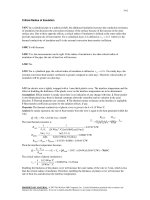
8-42 "!PROBLEM 8-42"
8-13
Chapter 8 Internal Forced Convection
"GIVEN"
T_i=85 "[C]"
L=10 "[m]"
side=0.15 "[m]"
"V_dot=0.10 [m^3/s], parameter to be varied"
T_s=70 "[C]"
"PROPERTIES"
Fluid$='air'
C_p=CP(Fluid$, T=T_ave)*Convert(kJ/kg-C, J/kg-C)
k=Conductivity(Fluid$, T=T_ave)
Pr=Prandtl(Fluid$, T=T_ave)
rho=Density(Fluid$, T=T_ave, P=101.3)
mu=Viscosity(Fluid$, T=T_ave)
nu=mu/rho
T_ave=1/2*(T_i+T_e)
"ANALYSIS"
D_h=(4*A_c)/p
A_c=side^2
p=4*side
Vel=V_dot/A_c
Re=(Vel*D_h)/nu "The flow is turbulent"
L_t=10*D_h "The entry length is much shorter than the total length of the duct."
Nusselt=0.023*Re^0.8*Pr^0.3
h=k/D_h*Nusselt
A=4*side*L
m_dot=rho*V_dot
T_e=T_s-(T_s-T_i)*exp((-h*A)/(m_dot*C_p))
DELTAT_ln=(T_e-T_i)/ln((T_s-T_e)/(T_s-T_i))
Q_dot=h*A*DELTAT_ln
8-14
Chapter 8 Internal Forced Convection
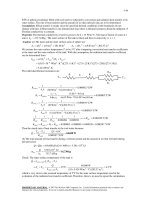
V [m3/s]
0.05
0.055
0.06
0.065
0.07
0.075
0.08
0.085
0.09
0.095
0.1
0.105
0.11
0.115
0.12
0.125
0.13
0.135
0.14
0.145
0.15
Te [C]
74.89
75
75.09
75.18
75.26
75.34
75.41
75.48
75.54
75.6
75.66
75.71
75.76
75.81
75.86
75.9
75.94
75.98
76.02
76.06
76.1
Q [W]
509
554.1
598.6
642.7
686.3
729.5
772.4
814.8
857
898.9
940.4
981.7
1023
1063
1104
1144
1184
1224
1264
1303
1343
76.2
1400
1300
75.9
1200
Te
T e [C]
1000
900
Q
75.3
800
700
75.1
600
74.8
0.04
0.06
0.08
0.1
3
V [m /s]
8-15
0.12
0.14
500
0.16
Q [W ]
1100
75.7
Chapter 8 Internal Forced Convection
8-43 Air enters the constant spacing between the glass cover and the plate of a solar collector. The net rate
of heat transfer and the temperature rise of air are to be determined.
Assumptions 1 Steady operating conditions exist. 2 The inner surfaces of the spacing are smooth. 3 Air is
an ideal gas with constant properties. 4 The local atmospheric pressure is 1 atm.
Properties The properties of air at 1 atm and estimated average temperature of 35°C are (Table A-15)
C p = 1007 J/kg.°C
ρ = 1.146kg/m 3
Pr = 0.7268
k = 0.02625 W/m.°C
υ = 1.655 × 10 -5 m 2 /s
Analysis Mass flow rate, cross sectional area, hydraulic diameter,
mean velocity of air and the Reynolds number are
Glass
cover
20°C
m& = ρV& = (1.146 kg/m 3 )(0.15 m 3 /s) = 0.1719 kg/s
Ac = (1 m)(0.03 m) = 0.03 m2
Dh =
4 Ac
4(0.03 m 2 )
=
= 0.05825 m
P
2(1 m + 0.03 m)
Vm =
015
. m3 / s
V&
=
= 5 m/s
Ac
0.03 m2
Re =
Vm Dh
=
(5 m/s)(0.05825 m)
Air
30°C
0.15 m3/min
60°C
Collector plate
(insulated)
= 17,606
υ
1.655 × 10 −5 m 2 /s
which is greater than 10,000. Therefore, the flow is turbulent and the entry lengths in this case are roughly
Lh ≈ Lt ≈ 10 Dh = 10(0.05825 m) = 0.5825 m
which are much shorter than the total length of the collector. Therefore, we can assume fully developed
turbulent flow in the entire collector, and determine the Nusselt number from
hDh
Nu =
= 0.023 Re0.8 Pr 0.4 = 0.023(17,606 )0.8 (0.7268)0.4 = 50.45
k
k
0.02625 W/m.°C
h=
Nu =
(50.45) = 22.73 W/m 2 .°C
and
Dh
0.05825 m
The exit temperature of air can be calculated using the “average” surface temperature as
As = 2(5 m)(1 m) = 10 m 2
Ts,ave =
60 + 20
= 40° C
2
⎛ hAs ⎞
⎟ = 40 − (40 − 30) exp⎛⎜ − 22.73 × 10 ⎞⎟ = 37.31°C
Te = Ts ,ave − (Ts ,ave − Ti ) exp⎜ −
⎜ m& C p ⎟
⎝ 0.1718 × 1007 ⎠
⎠
⎝
The temperature rise of air is
ΔT = 37.3°C − 30°C = 7.3°C
The logarithmic mean temperature difference and the heat loss from the glass are
T − Ti
37.31 − 30
=
= 13.32°C
ΔTln, glass = e
20 − 37.31
T s − Te
ln
ln
20 − 30
Ts − Ti
Q& glass = hAs ΔTln = (22.73 W/m 2 .°C)(5 m 2 )(13.32°C) = 1514 W
The logarithmic mean temperature difference and the heat gain of the absorber are
T − Ti
37.31 − 30
=
= 26.17°C
ΔTln,absorber = e
60 − 37.31
T s − Te
ln
ln
60 − 30
Ts − Ti
8-16
Chapter 8 Internal Forced Convection
Q& absorber = hAΔTln = (22.73 W/m 2 .°C)(5 m 2 )(26.17°C) = 2975 W
Then the net rate of heat transfer becomes
Q& = 2975 − 1514 = 1461 W
net
8-17
Chapter 8 Internal Forced Convection
8-44 Oil flows through a pipeline that passes through icy waters of a lake. The exit temperature of the oil
and the rate of heat loss are to be determined.
Assumptions 1 Steady operating conditions exist. 2 The surface temperature of the pipe is very nearly 0°C.
3 The thermal resistance of the pipe is negligible. 4 The inner surfaces of the pipeline are smooth. 5 The
flow is hydrodynamically developed when the pipeline reaches the lake.
(Icy lake, 0°C)
Properties The properties of oil at 10°C are (Table A-13)
ρ = 893.5 kg/m 3 ,
k = 0.146 W/m.°C
μ = 2.325 kg/m.s,
υ = 2591 × 10 m /s
C p = 1838 J/kg.°C,
-6
Oil
10°C
0.5 m/s
2
Pr = 28750
Vm D h
υ
=
(0.5 m/s)(0.4 m)
2591× 10 −6 m 2 /s
Te
L = 300 m
Analysis (a) The Reynolds number in this case is
Re =
D = 0.4 m
= 77.19
which is less than 2300. Therefore, the flow is laminar, and the thermal entry length is roughly
Lt = 0.05 Re Pr D = 0.05(77.19)(28750)(0.4 m ) = 44,384 m
which is much longer than the total length of the pipe. Therefore, we assume thermally developing flow,
and determine the Nusselt number from
hD
0.065( D / L) Re Pr
= 3.66 +
= 3.66 +
Nu =
k
1 + 0.04[( D / L) Re Pr ]2 / 3
⎛ 0.4 m ⎞
0.065⎜
⎟(77.19)(28,750)
⎝ 300 m ⎠
⎡⎛ 0.4 m ⎞
⎤
1 + 0.04⎢⎜
⎟(77.19)(28,750)⎥
300
m
⎠
⎣⎝
⎦
2/3
= 24.47
0.146 W/m.°C
k
Nu =
(24.47) = 8.930 W/m 2 .°C
D
0.4 m
Next we determine the exit temperature of oil
and
h=
As = πDL = π (0.4 m)(300 m) = 377 m 2
⎛ πD 2
m& = ρV& = ρAc Vm = ρ ⎜⎜
⎝ 4
Te = Ts − (Ts − Ti )e
− hAs /( m& C p )
⎞
π (0.4 m) 2
⎟Vm = (893.5 kg/m 3 )
(0.5 m/s) = 56.14 kg/s
⎟
4
⎠
= 0 − (0 − 10)e
−
(8.930 )( 377 )
(56.14 )(1838)
= 9.68 °C
(b) The logarithmic mean temperature difference and the rate of heat loss from the oil are
Te − Ti
9.68 − 10
ΔTln =
=
= 9.84°C
⎛ T s − Te ⎞
⎛ 0 − 9.68 ⎞
⎟ ln⎜
⎟
ln⎜⎜
⎟
⎝ 0 − 10 ⎠
⎝ Ts − Ti ⎠
Q& = hAs ΔTln = (8.930 W/m 2 .°C)(377 m 2 )(9.84°C) = 3.31× 10 4 W = 3.31 kW
The friction factor is
f =
64
64
=
= 0.8291
Re 77.19
Then the pressure drop in the pipe and the required pumping power become
ΔP = f
2
L ρVm
300 m (893.5 kg/m 3 )(0.5 m/s) 2
= 0.8291
D 2
0.4 m
2
⎞⎛ 1 kPa
⎛
1 kN
⎟⎟⎜
⎜⎜
2
⋅
1000
kg
m/s
⎠⎝ 1 kN/m
⎝
⎛ 1 kW
⎞
W& pump,u = V&ΔP = (0.0628 m 3 /s)(69.54 kPa )⎜
⎟ = 4.364 kW
3
⋅
⎝ 1 kPa m /s ⎠
8-18
⎞
⎟ = 69.54 kPa
⎠
Chapter 8 Internal Forced Convection
Discussion The power input determined is the mechanical power that needs to be imparted to the fluid. The
shaft power will be much more than this due to pump inefficiency; the electrical power input will be even
more due to motor inefficiency.
8-19
Chapter 8 Internal Forced Convection
8-45 Laminar flow of a fluid through an isothermal square channel is considered. The change in the
pressure drop and the rate of heat transfer are to be determined when the mean velocity is doubled.
Analysis The pressure drop of the fluid for laminar flow is expressed as
ΔP1 = f
64 υ L ρVm 2
υLρ
L ρVm 2 64 L ρVm 2
=
=
= 32 Vm 2
Re D 2
Vm D D 2
D 2
D
When the free-stream velocity of the fluid is doubled, the pressure drop becomes
ΔP2 = f
L ρ(2 Vm ) 2 64 L ρ4 Vm 2
64 υ L ρ4 Vm 2
υLρ
=
=
= 64 Vm 2
D
2
Re D 2
2 Vm D D 2
D
L
Their ratio is
ΔP2 64
=
=2
ΔP1 32
Laminar flow
Vm
The rate of heat transfer between the fluid and the walls of the channel is expressed as
1/ 3
k
k
⎛ Re Pr D ⎞
Q&1 = hAΔTln = NuAΔTln = 1.86⎜
⎟
D
D
L ⎠
⎝
1/ 3
V 1 / 3 D1 / 3 k
⎛ Re Pr D ⎞
= m 1/ 3
1.86⎜
⎟
D
L ⎠
υ
⎝
⎛ μb ⎞
⎜ ⎟
⎜μ ⎟
⎝ s⎠
⎛ μb ⎞
⎜ ⎟
⎜μ ⎟
⎝ s⎠
0.4
AΔTln
0.4
AΔTln
When the free-stream velocity of the fluid is doubled, the heat
transfer rate becomes
1/ 3
(2Vm )1 / 3 D1 / 3 k
⎛ Re Pr D ⎞
Q& 2 =
1.86⎜
⎟
1/ 3
D
L ⎠
υ
⎝
⎛ μb ⎞
⎜ ⎟
⎜μ ⎟
⎝ s⎠
0.4
AΔTln
Their ratio is
Q& 2 (2 Vm )1/ 3
=
= 21/ 3 = 1.26
Q&1
Vm1/ 3
Therefore, doubling the velocity will double the pressure drop but it will increase the heat transfer rate by
only 26%.
8-20
Chapter 8 Internal Forced Convection
8-46 Turbulent flow of a fluid through an isothermal square channel is considered. The change in the
pressure drop and the rate of heat transfer are to be determined when the free-stream velocity is doubled.
Analysis The pressure drop of the fluid for turbulent flow is expressed as
ΔP1 = f
V −0.2 D −0.2 L ρVm 2
L ρVm 2
L ρVm 2
= 0.184 Re − 0.2
= 0.184 m − 0.2
D 2
D 2
D 2
υ
⎛D⎞
= 0.092Vm1.8 ⎜ ⎟
⎝υ ⎠
− 0.2
Lρ
D
When the free-stream velocity of the fluid is doubled, the pressure drop becomes
ΔP2 = f
(2Vm ) −0.2 D −0.2 L ρ 4Vm 2
L ρ (2Vm ) 2
L ρ 4Vm 2
= 0.184 Re − 0.2
= 0.184
D
D
D
2
2
2
υ − 0.2
⎛D⎞
= 0.368(2) − 0.2 Vm1.8 ⎜ ⎟
⎝υ ⎠
− 0.2
Lρ
D
L
Their ratio is
1.8
ΔP2 0.368(2) −0.2 Vm
=
= 4(2) −0.2 = 3.48
1
.
8
ΔP1
0.092V m
Turbulent flow
Vm
The rate of heat transfer between the fluid and the walls of the channel is expressed as
k
k
Q&1 = hAΔTln = NuAΔTln = 0.023 Re0.8 Pr1 / 3 AΔTln
D
D
⎛D⎞
= 0.023Vm 0.8 ⎜ ⎟
⎝υ ⎠
0.8
k 1/ 3
Pr AΔTln
D
When the free-stream velocity of the fluid is doubled, the heat transfer rate becomes
⎛D⎞
Q& 2 = 0.023(2Vm )0.8 ⎜ ⎟
⎝υ ⎠
0.8
k 1/ 3
Pr AΔTln
D
Their ratio is
Q& 2 (2 Vm ) 0.8
=
= 2 0.8 = 1.74
Q&1
Vm 0.8
Therefore, doubling the velocity will increase the pressure drop 3.8 times but it will increase the heat
transfer rate by only 74%.
8-21
Chapter 8 Internal Forced Convection
8-47E Water is heated in a parabolic solar collector. The required length of parabolic collector and the
surface temperature of the collector tube are to be determined.
Assumptions 1 Steady operating conditions exist. 2 The thermal resistance of the tube is negligible. 3 The
inner surfaces of the tube are smooth.
Solar absorption,
350 Btu/h.ft
Properties The properties of water at the average temperature of
(55+200)/2 = 127.5°F are (Table A-9E)
ρ = 61.59 lbm/ft 3
k = 0.374 Btu/ft.°F
υ = μ / ρ = 0.5683 × 10
C p = 0.999Btu/lbm.°F
(Inside glass tube)
-5
2
ft /s
Water
55°F
4 lbm/s
Pr = 3.368
Analysis The total rate of heat transfer is
Q& = m& C (T − T ) = (4 lbm/s)(0.999 Btu/lbm.°F)(200 − 55)°F
p
e
D = 1.25 in
200°F
L
i
= 579.4 Btu/s = 2.086 × 10 6 Btu/h
The length of the tube required is
L=
Q& total 2.086 × 10 4 Btu/h
=
= 5960 ft
350 Btu/h.ft
Q&
The velocity of water and the Reynolds number are
Vm =
Re =
m&
=
ρAc
4 lbm/s
(1.25 / 12 ft ) 2
(61.59 lbm/m ) π
4
= 7.621 ft/s
3
Vm Dh (7.621 m/s)(1.25/12 ft)
=
= 1.397 × 10 5
υ
0.5683 × 10 −5 ft 2 /s
which is greater than 10,000. Therefore, we can assume fully developed turbulent flow in the entire tube,
and determine the Nusselt number from
Nu =
hDh
= 0.023 Re 0.8 Pr 0.4 = 0.023(1.397 × 10⁴ )0.8 (3.368)0.4 = 488.4
k
The heat transfer coefficient is
h=
k
0.374 Btu/h.ft.°F
Nu =
(488.4) = 1754 Btu/h.ft 2 .°F
Dh
1.25 / 12 ft
The heat flux on the tube is
Q&
2.086 × 10 4 Btu/h
=
= 1070 Btu/h.ft 2
q& =
As π (1.25 / 12 ft )(5960 ft )
Then the surface temperature of the tube at the exit becomes
⎯→ Ts = Te +
q& = h(Ts − Te ) ⎯
q&
1070 Btu/h.ft 2
= 200°F +
= 200.6°F
h
1754 Btu/h.ft 2 .°F
8-22
Chapter 8 Internal Forced Convection
8-48 A circuit board is cooled by passing cool air through a channel drilled into the board. The maximum
total power of the electronic components is to be determined.
Assumptions 1 Steady operating conditions exist. 2 The heat flux at the top surface of the channel is
uniform, and heat transfer through other surfaces is negligible. 3 The inner surfaces of the channel are
smooth. 4 Air is an ideal gas with constant properties. 5 The pressure of air in the channel is 1 atm.
Properties The properties of air at 1 atm and estimated average temperature of 25°C are (Table A-15)
ρ = 1.184 kg/m 3
Electronic components,
50°C
k = 0.02551 W/m.°C
Te
υ = 1.562 × 10 -5 m 2 /s
C p = 1007 J/kg.°C
Air
15°C
4 m/s
Pr = 0.7296
L = 20 cm
Air channel
0.2 cm × 14 cm
Analysis The cross-sectional and heat transfer surface areas are
Ac = (0.002 m )(0.14 m ) = 0.00028 m 2
As = (0.14 m )(0.2 m ) = 0.028 m 2
To determine heat transfer coefficient, we first need to find the Reynolds number,
Dh =
4 Ac
4(0.00028 m 2 )
=
= 0.003944 m
P
2(0.002 m + 0.14 m)
Re =
Vm D h
=
υ
(4 m/s)(0.003944 m)
1.562 × 10 −5 m 2 /s
= 1010
which is less than 2300. Therefore, the flow is laminar and the thermal entry length is
Lt = 0.05 Re Pr Dh = 0.05(1010)(0.7296)(0.003944 m) = 0.1453 m < 0.20 m
Therefore, we have developing flow through most of the channel. However, we take the conservative
approach and assume fully developed flow, and from Table 8-1 we read Nu = 8.24. Then the heat transfer
coefficient becomes
h=
k
0.02551 W/m.°C
Nu =
(8.24) = 53.30 W/m 2 .°C
Dh
0.003944 m
Also,
m& = ρVAc = (1.184 kg/m 3 )(4 m/s)(0.00028 m 2 ) = 0.001326 kg/s
Heat flux at the exit can be written as q& = h(Ts − Te ) where Ts = 50° C at the exit. Then the heat transfer
rate can be expressed as Q& = q&A = hA (T − T ) , and the exit temperature of the air can be determined
s
s
s
e
from
hAs (Ts − Te ) = m& C p (Te − Ti )
(53.30 W/m .°C)(0.028 m )(50°C − Te ) = (0.001326 kg/s )(1007 J/kg.°C)(Te − 15°C)
2
2
Te = 33.5°C
Then the maximum total power of the electronic components that can safely be mounted on this circuit
board becomes
Q&
= m& C (T − T ) = (0.001326 kg/s )(1007 J/kg.°C )(33.5 − 15°C) = 24.7 W
max
p
e
i
8-23
Chapter 8 Internal Forced Convection
8-49 A circuit board is cooled by passing cool helium gas through a channel drilled into the board. The
maximum total power of the electronic components is to be determined.
Assumptions 1 Steady operating conditions exist. 2 The heat flux at the top surface of the channel is
uniform, and heat transfer through other surfaces is negligible. 3 The inner surfaces of the channel are
smooth. 4 Helium is an ideal gas. 5 The pressure of helium in the channel is 1 atm.
Properties The properties of helium at the estimated average temperature of 25°C are (Table A-16)
ρ = 0.1635 kg/m 3
Electronic components,
50°C
k = 0.1565 W/m.°C
Te
υ = 1.233 × 10 - 4 m 2 /s
C p = 5193 J/kg.°C
He
15°C
4 m/s
Pr = 0.669
L = 20 cm
Air channel
0.2 cm × 14 cm
Analysis The cross-sectional and heat transfer surface areas are
Ac = (0.002 m )(0.14 m ) = 0.00028 m 2
As = (0.14 m )(0.2 m ) = 0.028 m 2
To determine heat transfer coefficient, we need to first find the Reynolds number
Dh =
4 Ac
4(0.00028 m 2 )
=
= 0.003944 m
P
2(0.002 m + 0.14 m)
Re =
Vm D h
υ
=
(4 m/s)(0.003944 m)
1.233 × 10 − 4 m 2 /s
= 127.9
which is less than 2300. Therefore, the flow is laminar and the thermal entry length is
Lt = 0.05 Re Pr Dh = 0.05(127.9)(0.669)(0.003944 m) = 0.01687 m << 0.20 m
Therefore, the flow is fully developed flow, and from Table 8-3 we read Nu = 8.24. Then the heat transfer
coefficient becomes
k
0.1565 W/m.°C
h=
Nu =
(8.24) = 327.0 W/m 2 .°C
Dh
0.003944 m
Also,
m& = ρVAc = (0.1635 kg/m 3 )(4 m/s)(0.00028 m 2 ) = 0.0001831 kg/s
Heat flux at the exit can be written as q& = h(Ts − Te ) where Ts = 50° C at the exit. Then the heat transfer
rate can be expressed as Q& = q&A = hA (T − T ) , and the exit temperature of the air can be determined
s
s
s
e
from
m& C p (Te − Ti ) = hAs (Ts − Te )
(0.0001831 kg/s )(5193 J/kg.°C)(Te − 15°C) = (327.0 W/m 2 .°C)(0.0568 m 2 )(50°C − Te )
Te = 46.7°C
Then the maximum total power of the electronic components that can safely be mounted on this circuit
board becomes
Q& max = m& C p (Te − Ti ) = (0.0001831 kg/s )(5193 J/kg.°C )( 46.7 − 15°C ) = 30.2 W
8-24
Chapter 8 Internal Forced Convection
8-50 "!PROBLEM 8-50"
"GIVEN"
L=0.20 "[m]"
width=0.14 "[m]"
height=0.002 "[m]"
T_i=15 "[C]"
Vel=4 "[m/s], parameter to be varied"
"T_s=50 [C], parameter to be varied"
"PROPERTIES"
Fluid$='air'
C_p=CP(Fluid$, T=T_ave)*Convert(kJ/kg-C, J/kg-C)
k=Conductivity(Fluid$, T=T_ave)
Pr=Prandtl(Fluid$, T=T_ave)
rho=Density(Fluid$, T=T_ave, P=101.3)
mu=Viscosity(Fluid$, T=T_ave)
nu=mu/rho
T_ave=1/2*(T_i+T_e)
"ANALYSIS"
A_c=width*height
A=width*L
p=2*(width+height)
D_h=(4*A_c)/p
Re=(Vel*D_h)/nu "The flow is laminar"
L_t=0.05*Re*Pr*D_h
"Taking conservative approach and assuming fully developed laminar flow, from Table 8-1
we read"
Nusselt=8.24
h=k/D_h*Nusselt
m_dot=rho*Vel*A_c
Q_dot=h*A*(T_s-T_e)
Q_dot=m_dot*C_p*(T_e-T_i)
8-25