solution manual heat and mass transfer a practical approach 3rd edition cengel chapter 15
Bạn đang xem bản rút gọn của tài liệu. Xem và tải ngay bản đầy đủ của tài liệu tại đây (1.58 MB, 79 trang )
15-1
Chapter 15
COOLING OF ELECTRONIC EQUIPMENT
Introduction and History
15-1C The invention of vacuum diode started the electronic age. The invention of the transistor marked the
beginning of a revolution in that age since the transistors performed the functions of the vacuum tubes with
greater reliability while occupying negligible space and consuming negligible power compared to the
vacuum tubes.
15-2C Integrated circuits are semiconductor devices in which several components such as diodes,
_Solution
Heat andThe
Mass
Transfer
Practical
Approach
Cengel Chapter
transistors, resistors and capacitors
areManual
housed-together.
initials
MSI,A LSI,
and VLSI
stand3rd
forEdition
medium
scale integration, large scale integration, and very large scale integration, respectively.
15-3C The electrical resistance R is a measure of resistance against current flow, and the friction between
the electrons and the material causes heating. The amount of the heat generated can be determined from
Ohm’s law, W = I 2 R .
15-4C The electrical energy consumed by the TV is eventually converted to heat, and the blanket wrapped
around the TV prevents the heat from escaping. Then the temperature of the TV set will have to start rising
as a result of heat build up. The TV set will have to burn up if operated this way for a long time. However,
for short time periods, the temperature rise will not reach destructive levels.
15-5C Since the heat generated in the incandescent light bulb which is completely wrapped can not escape,
the temperature of the light bulb will increase, and will possibly start a fire by igniting the towel.
15-6C When the air flow to the radiator is blocked, the hot water coming off the engine cannot be cooled,
and thus the engine will overheat and fail, and possible catch fire.
15-7C A car is much more likely to break since it has more moving parts than a TV.
15-8C Diffusion in semi-conductor materials, chemical reactions and creep in the bending materials cause
electronic components to fail under prolonged use at high temperatures.
PROPRIETARY MATERIAL. © 2007 The McGraw-Hill Companies, Inc. Limited distribution permitted only to teachers and
educators for course preparation. If you are a student using this Manual, you are using it without permission.
15-2
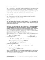
15-9 The case temperature of a power transistor and the
junction-to-case resistance are given. The junction
temperature is to be determined.
Case
Q
Tcase
Rjunction-case
Junction
Tjunction
Assumptions Steady operating conditions exist.
Analysis The rate of heat transfer between the
junction and the case in steady operation is
T junction − Tcase
⎛ ΔT ⎞
=
Q& = ⎜
⎟
R junction − case
⎝ R ⎠ junction − case
Then the junction temperature is determined to be
T junction = Tcase + Q& R junction − case = 60°C + (12 W)(5°C/W) = 120°C
15-10 The power dissipated by an electronic component
as well as the junction and case temperatures are
measured. The junction-to-case resistance is to be
determined.
Case
Q
Tcase
Rjunction-case
Assumptions Steady operating conditions exist.
Junction
Tjunction
Analysis The rate of heat transfer from the component is
W& e = Q& = VI = (12 V)(0.15 A) = 1.8 W
Then the junction-to-case thermal resistance of this
component becomes
R junction − case =
T junction − Tcase (80 − 55)°C
=
= 13.9°C/W
1.8 W
Q&
15-11 A logic chip dissipates 6 W power. The amount of heat this chip dissipates during a 10-h period and
the heat flux on the surface of the chip are to be determined.
Assumptions 1 Steady operating conditions exist. 2 Heat transfer from the surface is uniform.
Analysis (a) The amount of heat this chip dissipates
during an eight-hour workday is
Q&
Q = Q& Δt = (0.006 kW)(8 h) = 0.048 kWh
(b) The heat flux on the surface of the chip is
Q&
6W
= 18.8 W/cm 2
q& = =
A 0.32 cm 2
6W
Chip
A = 0.32 cm2
PROPRIETARY MATERIAL. © 2007 The McGraw-Hill Companies, Inc. Limited distribution permitted only to teachers and
educators for course preparation. If you are a student using this Manual, you are using it without permission.
15-3
15-12 A circuit board houses 90 closely spaced logic chips, each dissipating 0.1 W. The amount of heat
this chip dissipates in 10 h and the heat flux on the surface of the circuit board are to be determined.
Assumptions 1 Steady operating conditions exist. 2 The heat
transfer from the back surface of the board is negligible.
Analysis (a) The rate of heat transfer and the amount of heat this
circuit board dissipates during a ten-hour period are
Q&
= (90)(0.1 W) = 9 W
Chips
total
Q& = 9 W
Qtotal = Q& total Δt = (0.009 kW)(10 h) = 0.09 kWh
(b) The average heat flux on the surface of the circuit board is
q& =
Q& total
9W
=
= 0.03 W/cm 2
(15 cm)(20 cm)
As
15-13E The total thermal resistance and the temperature of
a resistor are given. The power at which it can operate
safely in a particular environment is to be determined.
Assumptions Steady operating conditions exist.
Resistor
Q&
Tresistor
Analysis The power at which this resistor can be operate
safely is determined from
T∞
Rtotal
− Tambient (360 − 120)°F
T
=
= 1.85 W
Q& = resistor
130°F/W
Rtotal
15-14 The surface-to-ambient thermal resistance and the surface temperature of a resistor are given. The
power at which it can operate safely in a particular environment is to be determined.
Assumptions Steady operating conditions exist.
Analysis The power at which this resistor can operate
safely is determined from
− Tambient (150 − 30)°C
T
=
= 0.4 W
Q& = resistor
300°C/W
Rtotal
At specified conditions, the resistor dissipates
2
2
V
(7.5 V)
Q& =
=
= 0.5625 W
R
(100 Ω)
Resistor
Q&
Tresistor
T∞
Rtotal
of power. Therefore, the current operation is not safe.
PROPRIETARY MATERIAL. © 2007 The McGraw-Hill Companies, Inc. Limited distribution permitted only to teachers and
educators for course preparation. If you are a student using this Manual, you are using it without permission.
15-4
15-15 EES Prob. 15-14 is reconsidered. The power at which the resistor can operate safely as a function of
the ambient temperature is to be plotted.
Analysis The problem is solved using EES, and the solution is given below.
"GIVEN"
R_electric=100 [ohm]
R_thermal=300 [C/W]
V=7.5 [volts]
T_resistor=150 [C]
T_ambient=30 [C]
"ANALYSIS"
Q_dot_safe=(T_resistor-T_ambient)/R_thermal
Qsafe [W]
0.4333
0.43
0.4267
0.4233
0.42
0.4167
0.4133
0.41
0.4067
0.4033
0.4
0.3967
0.3933
0.39
0.3867
0.3833
0.38
0.3767
0.3733
0.37
0.3667
0.44
0.43
0.42
0.41
Q safe [W ]
Tambient [C]
20
21
22
23
24
25
26
27
28
29
30
31
32
33
34
35
36
37
38
39
40
0.4
0.39
0.38
0.37
0.36
20
24
28
32
36
T am bient [C]
PROPRIETARY MATERIAL. © 2007 The McGraw-Hill Companies, Inc. Limited distribution permitted only to teachers and
educators for course preparation. If you are a student using this Manual, you are using it without permission.
40
15-5
Manufacturing of Electronic Equipment
15-16C The thermal expansion coefficient of the plastic is about 20 times that of silicon. Therefore,
bonding the silicon directly to the plastic case will result in such large thermal stresses that the reliability
would be seriously jeopardized. To avoid this problem, a lead frame made of a copper alloy with a thermal
expansion coefficient close to that of silicon is used as the bonding surface.
15-17C The schematic of chip carrier is given
in the figure. Heat generated at the junction is
transferred through the chip to the led frame,
then through the case to the leads. From the
leads heat is transferred to the ambient or to the
medium the leads are connected to.
Lid
Air gap
Junction
Bond wires
Case
Leads
Chip
Lead frame
Bond
15-18C The cavity of the chip carrier is filled with a gas which is a poor conductor of heat. Also, the case
is often made of materials which are also poor conductors of heat. This results in a relatively large thermal
resistance between the chip and the case, called the junction-to-case thermal resistance. It depends on the
geometry and the size of the chip carrier as well as the material properties of the bonding material and the
case.
15-19C A hybrid chip carrier houses several chips, individual electronic components, and ordinary circuit
elements connected to each other. The result is improved performance due to the shortening of the wiring
lengths, and enhanced reliability. Lower cost would be an added benefit of multi-chip packages if they are
produced in sufficiently large quantities.
15-20C A printed circuit board (PCB) is a properly wired plane board on which various electronic
components such as the ICs, diodes, transistors, resistors, and capacitors are mounted to perform a certain
task. The board of a PCB is made of polymers and glass epoxy materials. The thermal resistance between a
device on the board and edge of the board is called as device-to-PCB edge thermal resistance. This
resistance is usually high (about 20 to 60 °C /W) because of the low thickness of the board and the low
thermal conductivity of the board material.
15-21C The three types of circuit boards are the single-sided, double-sided, and multi-layer boards. The
single-sided PCBs have circuitry lines on one side of the board only, and are suitable for low density
electronic devices (10-20 components). The double-sided PCBs have circuitry on both sides, and are best
suited for intermediate density devices. Multi-layer PCBs contain several layers of circuitry, and they are
suitable for high density devices. They are equivalent to several PCBs sandwiched together.
15-22C The desirable characteristics of the materials used in the fabrication of circuit boards are: (1) being
an effective electrical insulator to prevent electrical breakdown, (2) being a good heat conductor to conduct
the heat generated away, (3) having high material strength to withstand the forces and to maintain
dimensional stability, (4) having a thermal expansion coefficient which closely matches to that of copper to
prevent cracking in the copper cladding during thermal cycling, (5) having a high resistance to moisture
absorption since moisture can effect both mechanical and electrical properties and degrade performance,
(6) stability in properties at temperature levels encountered in electronic applications, (7) ready availability
and manufacturability, and, of course (8) low cost.
PROPRIETARY MATERIAL. © 2007 The McGraw-Hill Companies, Inc. Limited distribution permitted only to teachers and
educators for course preparation. If you are a student using this Manual, you are using it without permission.
15-6
15-23C An electronic enclosure (a case or a cabinet) house the circuit boards and the necessary peripheral
equipment and connectors. It protects them from the detrimental effects of the environment, and may
provide a cooling path. An electronic enclosure can simply be made of sheet metals such as thin gauge
aluminum or steel.
Cooling Load of Electronic Equipment and Thermal Environment
15-24C The heating load of an electronic box which consumes 120 W of power is simply 120 W because
of the conservation of energy principle.
15-25C Superconductor materials will generate hardly any heat and as a result, more components can be
packed into a smaller volume, resulting in enhanced speed and reliability without having to resort to some
exotic cooling techniques.
15-26C The actual power dissipated by a device can be considerably less than its rated power, depending
on its duty cycle (the fraction of time it is on). A 5 W power transistor, for example, will dissipate an
average of 2 W of power if it is active only 40 percent of the time. Then we can treat this transistor as a 2W device when designing a cooling system. This may allow the selection of a simpler and cheaper cooling
mechanism.
15-27C The cyclic variation of temperature of an electronic device during operation is called the
temperature cycling. The thermal stresses caused by temperature cycling undermines the reliability of
electronic devices. The failure rate of electronic devices subjected to deliberate temperature cycling of
more than 20 °C is observed to increase by eight-fold.
15-28C The ultimate heat sink for a TV is the room air with a temperature range of about 10 to 30°C. For
an airplane it is the ambient air with a temperature range of about -50°C to 50°C. The ultimate heat sink for
a ship is the sea water with a temperature range of 0°C to 30°C.
15-29C The ultimate heat sink for a VCR is the room air with a temperature range of about 10 to 30°C. For
a spacecraft it is the ambient air or space with a temperature range of about -273°C to 50°C. The ultimate
heat sink for a communication system on top of a mountain is the ambient air with a temperature range of
about -20°C to 50°C.
Electronics Cooling in Different Applications
15-30C The electronics of short-range missiles do not need any cooling because of their short cruising
times. The missiles reach their destinations before the electronics reach unsafe temperatures. The longrange missiles must be cooled because of their long cruise times (several hours). The electronics in this
case are cooled by passing the liquid fuel they carry through the cold plate of the electronics enclosure as it
flows towards the combustion chamber.
15-31C Dynamic temperature is the rise in the temperature of a fluid as a result of the ramming effect or
the stagnation process. This is due to the conversion of kinetic energy to internal energy which is
significant at high velocities. It is determined from Tdynamic = V 2 /( 2c p ) where V is the velocity and c p is
the specific heat of the fluid. It is significant at velocities above 100 m/s.
PROPRIETARY MATERIAL. © 2007 The McGraw-Hill Companies, Inc. Limited distribution permitted only to teachers and
educators for course preparation. If you are a student using this Manual, you are using it without permission.
15-7
15-32C The electronic equipment in ships and submarines are usually housed in rugged cabinets to protect
them from vibrations and shock during stormy weather. Because of easy access to water, water cooled heat
exchangers are commonly used to cool sea-born electronics. Often air in a closed or open loop is cooled in
an air-to-water heat exchanger, and is forced to the electronic cabinet by a fan.
15-33C The electronics of communication systems operate for long periods of time under adverse
conditions such as rain, snow, high winds, solar radiation, high altitude, high humidity, and too high or too
low temperatures. Large communication systems are housed in specially built shelters. Sometimes it is
necessary to air-condition these shelters to safely dissipate the large quantities of heat generated by the
electronics of communication systems.
15-34C The electronic components used in the high power microwave equipment such as radars generate
enormous amounts of heat because of the low conversion efficiency of electrical energy to microwave
energy. The klystron tubes of high power radar systems where radio frequency (RF) energy is generated
can yield local heat fluxes as high as 2000 W/cm 2 . The safe and reliable dissipation of such high heat
fluxes usually require the immersion of such equipment into a suitable dielectric fluid which can remove
large quantities of heat by boiling.
15-35C The electronic equipment in space vehicles are usually cooled by a liquid circulated through the
components where heat is picked up, and then through a space radiator where the waste heat is radiated
into deep space at 0 K. In such systems it may be necessary to run a fan in the box to circulate the air since
there is no natural convection currents in space because of the absence of a gravity field.
15-36 An airplane cruising in the air at a temperature of
-25°C at a velocity of 850 km/h is considered. The
temperature rise of air is to be determined.
V = 850 km/h
Assumptions Steady operating conditions exist.
Analysis The temperature rise of air (dynamic
temperature) at this speed is
Tdynamic =
(850 × 1000 / 3600 m/s) 2
V2
=
2c p
(2)(1003 J/kg.°C)
⎛ 1 J/kg ⎞
⎜
⎟ = 27.8°C
⎝ 1 m 2 /s 2 ⎠
15-37 The temperature of air in the wind at a wind velocity of 90 km/h is
measured to be 12°C. The true temperature of air is to be determined.
Assumptions Steady operating conditions exist.
Analysis The temperature rise of air (dynamic temperature) at this speed is
Tdynamic
(90 × 1000 / 3600 m/s) 2
V2
=
=
2c p
(2)(1005 J/kg.°C)
⎛ 1 J/kg ⎞
⎜
⎟ = 0.3°C
⎝ 1 m 2 /s 2 ⎠
Wind
V = 90 km/h
Therefore, the true temperature of air is
Ttrue = Tmeasured − Tdynamic = (12 − 0.3)°C = 11.7°C
PROPRIETARY MATERIAL. © 2007 The McGraw-Hill Companies, Inc. Limited distribution permitted only to teachers and
educators for course preparation. If you are a student using this Manual, you are using it without permission.
15-8
15-38 EES Prob. 15-37 is reconsidered. The true temperature of air as a function of the wind velocity is to
be plotted.
Analysis The problem is solved using EES, and the solution is given below.
"GIVEN"
T_measured=12 [C]
Vel=90 [km/h]
"PROPERTIES"
C_p=CP(air, T=T_measured)*Convert(kJ/kg-C, J/kg-C)
"ANALYSIS"
T_dynamic=(Vel*Convert(km/h, m/s))^2/(2*C_p)*Convert(m^2/s^2, J/kg)
T_true=T_measured-T_dynamic
Ttrue [C]
11.98
11.98
11.97
11.95
11.94
11.92
11.9
11.88
11.86
11.84
11.81
11.78
11.75
11.72
11.69
11.65
11.62
11.58
11.54
11.49
11.45
12
11.9
11.8
T true [C]
Vel [km/h]
20
25
30
35
40
45
50
55
60
65
70
75
80
85
90
95
100
105
110
115
120
11.7
11.6
11.5
11.4
20
40
60
80
100
120
Vel [km /h]
PROPRIETARY MATERIAL. © 2007 The McGraw-Hill Companies, Inc. Limited distribution permitted only to teachers and
educators for course preparation. If you are a student using this Manual, you are using it without permission.
15-9
15-39 Air at 25°C is flowing in a channel. The temperature a stationary probe inserted into the channel will
read is to be determined for different air velocities.
Assumptions Steady operating conditions exist.
Analysis (a) The temperature rise of air (dynamic temperature) for an air velocity of 1 m/s is
Tdynamic =
(1 m/s) 2
V2
⎛ 1 J/kg ⎞
=
⎜
⎟ = 0.0005°C
2c p (2)(1005 J/kg.°C) ⎝ 1 m 2 /s 2 ⎠
Then the temperature which a stationary probe will read becomes
Tmeasured = Ttrue + Tdynamic = 25 + 0.0005 = 25.0005°C
(b) For an air velocity of 10 m/s the temperature rise is
Tdynamic =
Then,
(10 m/s) 2
V2
⎛ 1 J/kg ⎞
=
⎜
⎟ = 0.05°C
2c p (2)(1005 J/kg.°C) ⎝ 1 m 2 /s 2 ⎠
Tmeasured = Ttrue + Tdynamic = 25 + 0.05 = 25.05°C
(c) For an air velocity of 100 m/s the temperature rise is
Tdynamic =
Then,
Air, V
Ttrue = 25°C
Thermocouple
Tmeasured
(100 m/s) 2
V2
⎛ 1 J/kg ⎞
=
⎜
⎟ = 4.98°C
2c p (2)(1005 J/kg.°C) ⎝ 1 m 2 /s 2 ⎠
Tmeasured = Ttrue + Tdynamic = 25 + 4.98 = 29.98°C
(d) For an air velocity of 1000 m/s the temperature rise is
Tdynamic =
Then,
(1000 m/s) 2 ⎛ 1 J/kg ⎞
V2
=
⎜
⎟ = 497.5°C
2c p (2)(1005 J/kg.°C) ⎝ 1 m 2 /s 2 ⎠
Tmeasured = Ttrue + Tdynamic = 25 + 497.5 = 522.5°C
15-40 Power dissipated by an electronic device as well as its surface area and surface temperature are
given. A suitable cooling technique for this device is to be determined.
Q&
Assumptions Steady operating conditions exist.
Analysis The heat flux on the surface of this electronic device is
Q&
2W
=
= 0.4 W/cm 2
q& =
As 5 cm 2
2W
Chip
A = 5 cm2
For an allowable temperature rise of 50°C, the suitable cooling technique for this device is determined from
Fig. 15-17 to be forced convection with direct air.
PROPRIETARY MATERIAL. © 2007 The McGraw-Hill Companies, Inc. Limited distribution permitted only to teachers and
educators for course preparation. If you are a student using this Manual, you are using it without permission.
15-10
15-41E Power dissipated by a circuit board as well as its surface area
and surface temperature are given. A suitable cooling mechanism is to
be selected.
Assumptions Steady operating conditions exist.
Analysis The heat flux on the surface of this electronic device is
Q&
20 W
=
= 0.065 W/cm 2
q& =
As (6 in × 2.54 cm/in)(8 in × 2.54 cm/in)
Board
6 in × 8 in
Q& =20 W
For an allowable temperature rise of 80°F, the suitable cooling
technique for this device is determined from Fig. 15-17 to be natural
convection with direct air.
Conduction Cooling
15-42C The major considerations in the selection of a cooling technique are the magnitude of the heat
generated, the reliability requirements, the environmental conditions, and the cost.
15-43C Thermal resistance is the resistance of a materiel or device against heat flow through it. It is
analogous to electrical resistance in electrical circuits, and the thermal resistance networks can be analyzed
like electrical circuits.
15-44C If the rate of heat conduction through a medium Q& , and the thermal resistance R of the medium
are known, then the temperature difference across the medium can be determined from ΔT = Q& R .
15-45C The voltage drop across the wire is determined from ΔV = IR . The length of the wire is
proportional to the electrical resistance [ R = L /( ρA) ], which is proportional to the voltage drop. Therefore,
doubling the wire length while the current I is held constant will double the voltage drop.
The temperature drop across the wire is determined from ΔT = Q& R . The length of the wire is
proportional to the thermal resistance [ R = L /(kA) ], which is proportional to the temperature drop.
Therefore, doubling the wire length while the heat flow Q& is held constant will double the temperature
drop.
15-46C A heat frame is a thick metal plate attached to a circuit board. It enhances heat transfer by
providing a low resistance path for the heat flow from the circuit board to the heat sink. The thicker the
heat frame, the lower the thermal resistance and thus the smaller the temperature difference between the
center and the ends of the heat frame. The electronic components at the middle of a PCB operate at the
highest temperature since they are furthest away from the heat sink.
PROPRIETARY MATERIAL. © 2007 The McGraw-Hill Companies, Inc. Limited distribution permitted only to teachers and
educators for course preparation. If you are a student using this Manual, you are using it without permission.
15-11
15-47C Heat flow from the junction to the body of a chip is three-dimensional, but can be approximated as
being one-dimensional by adding a constriction thermal resistance to the thermal resistance network. For a
small heat generation area of diameter a on a considerably larger body, the constriction resistance is given
by Rconstriction = 1 /(2 π ak ) where k is the thermal conductivity of the larger body. The constriction
resistance is analogous to a partially closed valve in fluid flow, and a sudden drop in the cross-sectional
area of an wire in electric flow.
15-48C The junction-to-case thermal resistance of an electronic component is the overall thermal
resistance of all parts of the electronic component between the junction and case. In practice, this value is
determined experimentally. When the junction-to-case resistance, the power dissipation, and the case
temperature are known, the junction temperature of a component is determined from
T junctiion = Tcase + Q& R junction − case
15-49C The case-to-ambient thermal resistance of an electronic device is the total thermal resistance of all
parts of the electronic device between its outer surface and the ambient. In practice, this value is
determined experimentally. Usually, manufacturers list the total resistance between the junction and the
ambient for devices they manufacture for various configurations and ambient conditions likely to be
encountered. When the case-to-ambient resistance, the power dissipation, and the ambient temperature are
known, the junction temperature of the device is determined from T junctiion = Tambient + Q& R junction − ambient
15-50C The junction temperature in this case is determined from
(
)
T junctiion = Tambient + Q& R junction − case + R case − ambient .
When R junction−case > Rcase − ambient , the case temperature will be closer to the ambient temperature.
15-51C The PCBs are made of electrically insulating materials such as glass-epoxy laminates which are
poor conductors of heat. Therefore, the rate of heat conduction along a PCB is very low. Heat conduction
from the mid parts of a PCB to its outer edges can be improved by attaching heat frames or clamping cold
plates to it. Heat conduction across the thickness of the PCB can be improved by planting copper or
aluminum pins across the thickness of the PCB to serve as thermal bridges.
15-52C The thermal expansion coefficients of aluminum and copper are about twice as large as that of the
epoxy-glass. This large difference in the thermal expansion coefficients can cause warping on the PCBs if
the epoxy and the metal are not bonded properly. Warping is a major concern because it decreases
reliability. One way of avoiding warping is to use PCBs with components on both sides.
15-53C The thermal conduction module received a lot of attention from thermal designers because the
thermal design was incorporated at the initial stages of electrical design. The TCM was different from
previous chip designs in that it incorporated both electrical and thermal considerations in early stages of
design. The cavity in the TCM is filled with helium (instead of air) because of its very high thermal
conductivity (about six times that of air).
PROPRIETARY MATERIAL. © 2007 The McGraw-Hill Companies, Inc. Limited distribution permitted only to teachers and
educators for course preparation. If you are a student using this Manual, you are using it without permission.
15-12
15-54 The dimensions and power dissipation of a chip are given. The junction temperature of the chip is to
be determined.
Assumptions 1 Steady operating conditions exist. 2 Heat transfer through various components is onedimensional. 3 Heat transfer through the air gap and the lid on top of the chip is negligible because of the
very large thermal resistance involved along this path.
Analysis The various thermal resistances on the path of primary heat flow are
Rconstriction =
Rchip =
Rbond
1
2 π ak
=
1
2 π (0.5 × 10
−3
m)(120 W/m.°C)
= 4.7°C/W
L
0.5 × 10 -3 m
=
= 0.26°C/W
kA (120 W/m.°C)(0.004 × 0.004)m 2
L
0.05 × 10 -3 m
=
=
= 0.011°C/W
kA (296 W/m.°C)(0.004 × 0.004)m 2
Rconstriction
-3
Rlead =
L
0.25 × 10 m
= 0.04°C/W
=
kA (386 W/m.°C)(0.004 × 0.004)m 2
R plastic =
L
0.3 × 10 -3 m
=
= 66.67°C/W
kA (1 W/m.°C)(18 × 0.001× 0.00025)m 2
Rleads =
L
6 × 10 -3 m
=
= 3.45°C/W
kA (386 W/m.°C)(18 × 0.001× 0.00025)m 2
frame
Junction
Since all resistances are in series, the total thermal resistance between
the junction and the leads is determined by simply adding them up
Rtotal = R junction −lead
Rchip
Rbond
Rlead frame
= Rconstriction + Rchip + Rbond + Rlead + R plastic + Rleads
frame
Rplastic
= 4.7 + 0.26 + 0.011 + 0.04 + 66.67 + 3.45
= 75.13°C/W
Knowing the junction-to-leads thermal
resistance, the junction temperature is
determined from
Q& =
Rleads
T junction − Tleads
R junction − case
T junction = Tleads + Q& R junction − case = 50°C + (0.8 W)(75.13°C/W) = 110.1 °C
PROPRIETARY MATERIAL. © 2007 The McGraw-Hill Companies, Inc. Limited distribution permitted only to teachers and
educators for course preparation. If you are a student using this Manual, you are using it without permission.
15-13
15-55 A plastic DIP with 16 leads is cooled by forced air. Using data supplied by the manufacturer, the
junction temperature is to be determined.
Assumptions Steady operating conditions exist.
Air
25°C
300 m/min
Analysis The junction-to-ambient thermal resistance of
the device with 16 leads corresponding to an air velocity
of 300 m/min is determined from Fig.15-23 to be
R junction− ambient = 50°C/W
2W
Then the junction temperature becomes
Q& =
T junction − Tambient
R junction − ambient
T junction = Tambient + Q& R junction − ambient = 25°C + (2 W)(50°C/W) = 125°C
When the fan fails the total thermal resistance is determined from Fig.15-23 by reading the value for zero
air velocity (the intersection point of the curve with the vertical axis) to be
R junction− ambient = 70°C/W
which yields
Q& =
T junction − Tambient
R junction − ambient
T junction = Tambient + Q& R junction − ambient = 25°C + (2 W)(70°C/W) = 165°C
15-56 A PCB with copper cladding is given. The percentages of heat conduction along the copper and
epoxy layers as well as the effective thermal conductivity of the PCB are to be determined.
Assumptions 1 Steady operating conditions exist. 2 Heat conduction along the PCB is one-dimensional
since heat transfer from side surfaces is negligible. 3 The thermal properties of epoxy and copper layers are
constant.
Analysis Heat conduction along a layer is proportional to
the thermal conductivity-thickness product (kt) which is
determined for each layer and the entire PCB to be
-3
(kt ) copper = (386 W/m.°C)(0.06 × 10 m) = 0.02316 W/°C
PCB
12 cm
12 cm
Q
-3
(kt ) epoxy = (0.26 W/m.°C)(0.5 × 10 m) = 0.00013 W/°C
(kt ) PCB = (kt ) copper + (kt ) epoxy = 0.02316 + 0.00013 = 0.02329 W/°C
Therefore the percentages of heat conduction along the
epoxy board are
f epoxy =
and
(kt ) epoxy
(kt ) PCB
=
0.00013 W/°C
= 0.0056 ≅ 0.6%
0.02316 W/°C
Copper
t = 0.06 mm
Epoxy
t = 0.5 mm
f copper = (100 − 0.6)% = 99.4%
Then the effective thermal conductivity becomes
k eff =
(kt ) epoxy + (kt ) copper
t epoxy + t copper
=
(0.02316 + 0.00013) W/ °C
(0.06 + 0.5) × 10 -3 m
= 41.6 W/m.°C
PROPRIETARY MATERIAL. © 2007 The McGraw-Hill Companies, Inc. Limited distribution permitted only to teachers and
educators for course preparation. If you are a student using this Manual, you are using it without permission.
15-14
15-57 EES Prob. 15-56 is reconsidered. The effect of the thickness of the copper layer on the percentage
of heat conducted along the copper layer and the effective thermal conductivity of the PCB is to be
investigated.
Analysis The problem is solved using EES, and the solution is given below.
"GIVEN"
length=0.12 [m]
width=0.12 [m]
t_copper=0.06 [mm]
t_epoxy=0.5 [mm]
k_copper=386 [W/m-C]
k_epoxy=0.26 [W/m-C]
"ANALYSIS"
kt_copper=k_copper*t_copper*Convert(mm, m)
kt_epoxy=k_epoxy*t_epoxy*Convert(mm, m)
kt_PCB=kt_copper+kt_epoxy
f_copper=kt_copper/kt_PCB*Convert(, %)
f_epoxy=100-f_copper
k_eff=(kt_epoxy+kt_copper)/((t_epoxy+t_copper)*Convert(mm, m))
0.02
0.025
0.03
0.035
0.04
0.045
0.05
0.055
0.06
0.065
0.07
0.075
0.08
0.085
0.09
0.095
0.1
98.34
98.67
98.89
99.05
99.17
99.26
99.33
99.39
99.44
99.48
99.52
99.55
99.58
99.61
99.63
99.65
99.66
keff
[W/mC
]
15.1
18.63
22.09
25.5
28.83
32.11
35.33
38.49
41.59
44.64
47.63
50.57
53.47
56.31
59.1
61.85
64.55
99.8
70
99.6
f copper
60
99.4
50
99.2
k eff
99
40
98.8
30
98.6
20
98.4
98.2
0.02
0.03
0.04
0.05
0.06
0.07
0.08
0.09
10
0.1
t copper [mm ]
PROPRIETARY MATERIAL. © 2007 The McGraw-Hill Companies, Inc. Limited distribution permitted only to teachers and
educators for course preparation. If you are a student using this Manual, you are using it without permission.
k e ff [ W /m -C]
fcopper
[%]
f copper [% ]
Tcopper
[mm]
15-15
15-58 The heat generated in a silicon chip is conducted
to a ceramic substrate to which it is attached. The
temperature difference between the front and back
surfaces of the chip is to be determined.
Assumptions 1 Steady operating conditions exist. 2 Heat
conduction along the chip is one-dimensional.
Q&
3W
Chip
6×6×0.5 mm
Ceramic
substrate
Analysis The thermal resistance of silicon chip is
Rchip =
L
0.5 × 10 -3 m
=
= 0.1068°C/W
kA (130 W/m.°C)(0.006 × 0.006)m 2
Then the temperature difference across the chip becomes
ΔT = Q& R
= (3 W)(0.1068 °C/W) = 0.32°C
chip
15-59E The dimensions of an epoxy glass laminate are given. The
thermal resistances for heat flow along the layers and across the
thickness are to be determined.
Qlength
Assumptions 1 Heat conduction in the laminate is one-dimensional in
either case. 2 Thermal properties of the laminate are constant.
Analysis The thermal resistances of the PCB along the 7 in long side
and across its thickness are
R along
length
7 in
Qthickness
L
=
kA
(7/12) ft
(0.15 Btu/h.ft.°F)(6/12 ft)(0.05/12 ft)
= 1867 h.°F/Btu
=
(a)
R across
(b)
6 in
=
L
kA
=
(0.05/12) ft
= 0.095 h.°F/Btu
(0.15 Btu/h.ft.°F)(7/12 ft)(6/12 ft)
thickness
0.05 in
PROPRIETARY MATERIAL. © 2007 The McGraw-Hill Companies, Inc. Limited distribution permitted only to teachers and
educators for course preparation. If you are a student using this Manual, you are using it without permission.
15-16
15-60 Cylindrical copper fillings are
planted throughout an epoxy glass
board. The thermal resistance of the
board across its thickness is to be
determined.
3 mm
Assumptions 1 Heat conduction along
the board is one-dimensional. 2
Thermal properties of the board are
constant.
Analysis The number of copper
fillings on the board is
Copper
filing
1 mm
3 mm
Epoxy
board
Area of board
Area of one square
(150 mm)(180 mm)
=
= 3000
(3 mm)(3 mm)
n=
The surface areas of the copper fillings and the remaining part of the epoxy layer are
Atotal
πD 2
π (0.001 m) 2
= 0.002356 m 2
4
4
= (length)( width ) = (0.15 m)(0.18 m) = 0.027 m 2
Acopper = n
= (3000)
Aepoxy = Atotal − Acopper = 0.027 − 0.002356 = 0.024644 m 2
The thermal resistance of each material is
0.0014 m
L
=
= 0.00154°C/W
kA (386 W/m.°C)(0.002356 m 2 )
0.0014 m
L
=
=
= 0.2185°C/W
kA (0.26 W/m.°C)(0.024644 m 2 )
Rcopper =
Repoxy
Since these two resistances are in parallel, the equivalent thermal resistance of the entire board is
1
Rboard
=
1
Repoxy
+
1
Rcopper
=
1
1
+
⎯
⎯→ Rboard = 0.00153°C/W
0.2185°C/W 0.00154°C/W
PROPRIETARY MATERIAL. © 2007 The McGraw-Hill Companies, Inc. Limited distribution permitted only to teachers and
educators for course preparation. If you are a student using this Manual, you are using it without permission.
15-17
15-61 EES Prob. 15-60 is reconsidered. The effects of the thermal conductivity and the diameter of the
filling material on the thermal resistance of the epoxy board are to be investigated.
Analysis The problem is solved using EES, and the solution is given below.
"GIVEN"
length=0.18 [m]
width=0.15 [m]
k_epoxy=0.26 [W/m-C]
t_board=1.4/1000 [m]
k_filling=386 [W/m-C]
D_filling=1 [mm]
s=3/1000 [m]
"ANALYSIS"
A_board=length*width
n_filling=A_board/s^2
A_filling=n_filling*pi*(D_filling*Convert(mm, m))^2/4
A_epoxy=A_board-A_filling
R_filling=t_board/(k_filling*A_filling)
R_epoxy=t_board/(k_epoxy*A_epoxy)
1/R_board=1/R_epoxy+1/R_filling
Rboard
[C/W]
0.04671
0.01844
0.01149
0.008343
0.00655
0.005391
0.00458
0.003982
0.003522
0.003157
0.00286
0.002615
0.002408
0.002232
0.00208
0.001947
0.00183
0.001726
0.001634
0.00155
0.001475
0.05
0.04
R board [C/W ]
kfilling
[W/m-C]
10
29.5
49
68.5
88
107.5
127
146.5
166
185.5
205
224.5
244
263.5
283
302.5
322
341.5
361
380.5
400
0.03
0.02
0.01
0
0
50
100
150
200
250
300
350
400
k filling [W /m -C]
PROPRIETARY MATERIAL. © 2007 The McGraw-Hill Companies, Inc. Limited distribution permitted only to teachers and
educators for course preparation. If you are a student using this Manual, you are using it without permission.
15-18
Rboard
[C/W]
0.005977
0.004189
0.003095
0.002378
0.001884
0.001529
0.001265
0.001064
0.0009073
0.0007828
0.0006823
0.0005999
0.0005316
0.0004743
0.0004258
0.0003843
0.006
0.005
0.004
R board [C/W ]
Dfilling
[mm]
0.5
0.6
0.7
0.8
0.9
1
1.1
1.2
1.3
1.4
1.5
1.6
1.7
1.8
1.9
2
0.003
0.002
0.001
0
0.5
0.8
1.1
1.4
1.7
D filling [m m ]
PROPRIETARY MATERIAL. © 2007 The McGraw-Hill Companies, Inc. Limited distribution permitted only to teachers and
educators for course preparation. If you are a student using this Manual, you are using it without permission.
2
15-19
15-62 A circuit board with uniform heat generation is to be conduction cooled by a copper heat frame.
Temperature distribution along the heat frame and the maximum temperature in the PCB are to be
determined.
15 cm × 18 cm
Assumptions 1 Steady operating conditions exist 2
Thermal properties are constant. 3 There is no direct
heat dissipation from the surface of the PCB, and
thus all the heat generated is conducted by the heat
frame to the heat sink.
Epoxy
Heat frame
Analysis The properties and dimensions of various
adhesive
Cold plate
section of the PCB are summarized below as
Section and material
Thermal
Thickness
Heat transfer surface
conductivity
area
Epoxy board
2 mm
0.26 W/m. °C
10 mm × 120 mm
Epoxy adhesive
0.12 mm
1.8 W/m. °C
10 mm × 120 mm
Copper heat frame
1.5 mm
386 W/m. °C
10 mm × 120 mm
(normal to frame)
Copper heat frame
10 mm
386 W/m. °C
15 mm × 120 mm
(along the frame)
Using the values in the table, the various thermal resistances are determined to be
L
0.002 m
Repoxy =
=
= 6.41°C/W
T9
kA (0.26 W/m.°C)(0.01 m × 0.12 m)
L
0.00012 m
R adhesive =
=
= 0.056°C/W
3W
Repox
kA (1.8 W/m.°C)(0.01 m × 0.12 m)
L
0.0015 m
=
= 0.0032°C/W
kA (386 W/m.°C)(0.01 m × 0.12 m)
L
0.01 m
= Rcopper , parallel =
=
= 0.144°C/W
kA (386 W/m.°C)(0.0015 × 0.12 m)
Rcopper ,⊥ =
R frame
22.5 W
19.5 W
T1
T0
16.5 W
T2
13.5 W
T3
T4
10.5 W
T5
7.5 W
4.5 W
T6
T7
1.5 W
T8
Radhesive
Rcopper ⊥
The combined resistance between the electronic components on each strip and the heat frame can be
determined by adding the three thermal resistances in series to be
Rvertical = Repoxy + R adhesive + Rcopper, ⊥ = 6.41 + 0.056 + 0.0032 = 6.469°C/W
The temperatures along the heat frame can be determined from the relation ΔT = Thigh − Tlow = Q& R . Then,
T1 = T0 + Q& 1− 0 R1− 0 = 30°C + (22.5 W)(0.144°C/W) = 33.24°C
T2 = T1 + Q& 2 −1 R 2−1 = 33.24°C + (19.5 W)(0.144°C/W) = 36.05°C
T = T + Q& R
= 36.05°C + (16.5 W)(0.144°C/W) = 38.42°C
3
2
3− 2
3− 2
T4 = T3 + Q& 4 −3 R 4−3 = 38.42°C + (13.5 W)(0.144°C/W) = 40.36°C
T5 = T4 + Q& 5− 4 R5− 4 = 40.36°C + (10.5 W)(0.144°C/W) = 41.87°C
T = T + Q& R
= 41.87°C + (7.5 W)(0.144°C/W) = 42.95°C
6
5
6 −5
6−5
T7 = T6 + Q& 7 − 6 R7 − 6 = 42.95°C + (4.5 W)(0.144°C/W) = 43.60°C
T8 = T7 + Q& 8−7 R8− 7 = 43.88°C + (1.5 W)(0.144°C/W) = 43.81°C
The maximum surface temperature on the PCB is
Tmax = T9 = T8 + Q& vertical Rvertical = 43.81°C + (3 W)(6.469°C/W) = 63.2°C
PROPRIETARY MATERIAL. © 2007 The McGraw-Hill Companies, Inc. Limited distribution permitted only to teachers and
educators for course preparation. If you are a student using this Manual, you are using it without permission.
15-20
15-63 A circuit board with uniform heat generation is to be conduction cooled by aluminum wires inserted
into it. The magnitude and location of the maximum temperature in the PCB is to be determined.
Assumptions 1 Steady operating conditions exist 2 Thermal properties are constant. 3 There is no direct
heat dissipation from the surface of the PCB.
Analysis The number of wires in the board is
Double sided
PCB
12 cm × 15 cm
150 mm
n=
= 75
2 mm
Aluminum
wire,
D = 1 mm
The surface areas of the aluminum wires and the
remaining part of the epoxy layer are
2 mm
π (0.001 m) 2
= (75)
= 0.0000589 m 2
4
4
= (length)( width ) = (0.003 m)(0.15 m) = 0.00045 m 2
Aalu min um = n
Atotal
πD
2
Aepoxy = Atotal − Aalu min um = 0.00045 − 0.0000589 = 0.0003911 m 2
Considering only half of the circuit board because of symmetry, the
thermal resistance of each material per 1-cm length is determined to be
3 mm
15 W
13.5 W
12 W
10.5 W
9W
7.5 W
30°C
6W
4.5 W
3W
1.5 W
Tmax
1 cm
Rboard
L
0.01 m
=
= 0.716°C/W
kA (237 W/m.°C)(0.0000589 m 2 )
L
0.01 m
=
=
= 98.34°C/W
kA (0.26 W/m.°C)(0.0003911 m 2 )
R alu min um =
Repoxy
Since these two resistances are in parallel, the equivalent thermal resistance per cm is determined from
1
1
1
1
1
=
+
=
+
⎯
⎯→ Rboard = 0.711°C/W
Rboard
R epoxy R alu min um 0.716°C/W 98.34°C/W
Maximum temperature occurs in the middle of the plate along the 20 cm length, which is determined to be
Tmax = Tend + ΔTboard ,total = Tend +
∑ Q& R
i
board ,1− cm
= Tend + Rboard ,1−cm
∑ Q&
i
= 30°C + (0.711°C/W)(15 + 13.5 + 12 + 10.5 + 9 + 7.5 + 6 + 4.5 + 3 + 1.5)W = 88.7°C
PROPRIETARY MATERIAL. © 2007 The McGraw-Hill Companies, Inc. Limited distribution permitted only to teachers and
educators for course preparation. If you are a student using this Manual, you are using it without permission.
15-21
15-64 A circuit board with uniform heat generation is to be conduction cooled by copper wires inserted in
it. The magnitude and location of the maximum temperature in the PCB is to be determined.
Assumptions 1 Steady operating conditions exist 2 Thermal properties are constant. 3 There is no direct
heat dissipation from the surface of the PCB.
Analysis The number of wires in the circuit board is
Double sided
PCB
12 cm × 15 cm
150 mm
n=
= 75
2 mm
Copper
wire,
D = 1 mm
The surface areas of the copper wires and the remaining
part of the epoxy layer are
2 mm
π (0.001 m) 2
= (75)
= 0.0000589 m 2
4
4
= (length)( width ) = (0.003 m)(0.15 m) = 0.00045 m 2
Acopper = n
Atotal
πD 2
Aepoxy = Atotal − Acopper = 0.00045 − 0.0000589 = 0.0003911 m 2
Considering only half of the circuit board because of symmetry, the
thermal resistance of each material per 1-cm length is determined to be
3 mm
15 W
13.5 W
12 W
10.5 W
9W
7.5 W
6W
4.5 W
3W
1.5 W
Tmax
30°C
1 cm
Rboard
L
0.01 m
=
= 0.440°C/W
kA (386 W/m.°C)(0.00005 89 m 2 )
L
0.01 m
=
=
= 98.34°C/W
kA (0.26 W/m.°C)(0.00039 11 m 2 )
R copper =
R epoxy
Since these two resistances are in parallel, the equivalent thermal resistance is determined from
1
1
1
1
1
=
+
=
+
⎯
⎯→ Rboard = 0.438°C/W
Rboard
R epoxy R copper 0.440°C/W 98.34°C/W
Maximum temperature occurs in the middle of the plate along the 20 cm length which is determined to be
Tmax = Tend + ΔTboard ,total = Tend +
∑ Q& R
i
board ,1− cm
= Tend + Rboard ,1− cm
∑ Q&
i
= 30° C + (0.438° C / W)(15 +13.5 +12 +10.5 + 9 + 7.5 + 6 + 4.5 + 3 +1.5)W = 66.1° C
PROPRIETARY MATERIAL. © 2007 The McGraw-Hill Companies, Inc. Limited distribution permitted only to teachers and
educators for course preparation. If you are a student using this Manual, you are using it without permission.
15-22
15-65 A circuit board with uniform heat generation is to be conduction cooled by aluminum wires inserted
into it. The magnitude and location of the maximum temperature in the PCB is to be determined.
Assumptions 1 Steady operating conditions exist 2 Thermal properties are constant. 3 There is no direct
heat dissipation from the surface of the PCB.
Analysis The number of wires in the board is
n=
Double sided
PCB
12 cm × 15 cm
150 mm
= 37
4 mm
Aluminum
wire,
D = 1 mm
The surface areas of the aluminum wires and the
remaining part of the epoxy layer are
π (0.001 m)
4 mm
2
= 0.000029 m 2
4
4
= (length)( width) = (0.003 m)(0.15 m) = 0.00045 m 2
Aalu min um = n
Atotal
πD
2
= (37)
Aepoxy = Atotal − Aalu min um = 0.00045 − 0.000029 = 0.000421 m 2
Considering only half of the circuit board because of symmetry, the
thermal resistance of each material per 1-cm length is determined to be
15 W
13.5 W
12 W
10.5 W
9W
7.5 W
6W
3 mm
4.5 W
3W
1.5 W
Tmax
30°C
1 cm
Rboard
0.01 m
L
=
= 1.455°C/W
kA (237 W/m.°C)(0.000029 m 2 )
0.01 m
L
=
=
= 91.36°C/W
kA (0.26 W/m.°C)(0.000421 m 2 )
R alu min um =
R epoxy
Since these two resistances are in parallel, the equivalent thermal resistance is determined from
1
1
1
1
1
=
+
=
+
⎯
⎯→ Rboard = 1.432°C/W
Rboard
R epoxy R alu min um 1.455°C/W 91.36°C/W
Maximum temperature occurs in the middle of the plate along the 20 cm length which is determined to be
Tmax = Tend + ΔTboard ,total = Tend +
∑ Q& R
i
board ,1− cm
= Tend + Rboard ,1−cm
∑ Q&
i
= 30°C + (1.432°C/W)(15 + 13.5 + 12 + 10.5 + 9 + 7.5 + 6 + 4.5 + 3 + 1.5)W = 148.1°C
PROPRIETARY MATERIAL. © 2007 The McGraw-Hill Companies, Inc. Limited distribution permitted only to teachers and
educators for course preparation. If you are a student using this Manual, you are using it without permission.
15-23
15-66 A thermal conduction module with 80 chips is cooled by water.
The junction temperature of the chip is to be determined.
Junction
Assumptions 1 Steady operating conditions exist 2 Heat transfer
through various components is one-dimensional.
Rchip
4W
Analysis The total thermal resistance between the junction and
cooling water is
Rinternal
Rtotal = R junction− water = Rchip + Rint ernal + Rexternal = 1.2 + 9 + 7 = 17.2°C
Rexternal
Then the junction temperature becomes
T junction = T water + Q& R junction − water = 18°C + (4 W)(17.2 °C/W) = 86.8°C
Cooling water
15-67 A layer of copper is attached to the back surface of an epoxy board. The effective thermal
conductivity of the board and the fraction of heat conducted through copper are to be determined.
Assumptions 1 Steady operating conditions exist 2 Heat
transfer is one-dimensional.
Analysis Heat conduction along a layer is proportional
to the thermal conductivity-thickness product (kt) which
is determined for each layer and the entire PCB to be
PCB
15 cm
20 cm
Q
(kt ) copper = (386 W/m.°C)(0.0001 m) = 0.0386 W/°C
(kt ) epoxy = (0.26 W/m.°C)(0.0003 m) = 0.000078 W/°C
(kt ) PCB = (kt ) copper + (kt ) epoxy = 0.0386 + 0.000078 = 0.038678 W/°C
The effective thermal conductivity can be determined from
k eff =
(kt ) epoxy + (kt ) copper
t epoxy + t copper
=
Copper,
t = 0.1 mm
Epoxy,
t = 0.3 mm
(0.0386 + 0.000078) W/ °C
= 96.7 W/m.°C
(0.0003 m + 0.0001 m)
Then the fraction of the heat conducted along the copper becomes
f =
(kt ) copper
(kt ) PCB
=
0.0386 W/°C
= 0.998 = 99.8%
0.038678 W/°C
Discussion Note that heat is transferred almost entirely through the copper layer.
PROPRIETARY MATERIAL. © 2007 The McGraw-Hill Companies, Inc. Limited distribution permitted only to teachers and
educators for course preparation. If you are a student using this Manual, you are using it without permission.
15-24
15-68 A copper plate is sandwiched between two epoxy boards. The effective thermal conductivity of the
board and the fraction of heat conducted through copper are to be determined.
Assumptions 1 Steady operating conditions exist 2 Heat
transfer is one-dimensional.
Copper,
t = 0.5 mm
12 cm
Analysis Heat conduction along a layer is proportional
to the thermal conductivity-thickness product (kt) which
is determined for each layer and the entire PCB to be
(kt ) copper = (386 W/m.°C)(0.0005 m) = 0.193 W/°C
(kt ) epoxy = (2)(0.26 W/m.°C)(0.003 m) = 0.00156 W/°C
(kt ) PCB = (kt ) copper + (kt ) epoxy = 0.193 + 0.00156 = 0.19456 W/°C
Q
The effective thermal conductivity can be determined from
k eff =
(kt ) epoxy + (kt ) copper
t epoxy + t copper
=
(0.00156 + 0.193) W/ °C
= 29.9 W/m.°C
[(2 × 0.003 m) + 0.0005 m]
Then the fraction of the heat conducted along the copper becomes
f =
(kt ) copper
(kt ) PCB
=
Epoxy,
t = 3 mm
0.193 W/°C
= 0.992 = 99.2%
0.19456 W/°C
15-69E A copper heat frame is used to conduct heat generated in a PCB. The temperature difference
between the mid section and either end of the heat frame is to be determined.
Assumptions 1 Steady operating conditions exist 2 Heat
transfer is one-dimensional.
PCB
6 in × 8 in
Analysis We assume heat is generated uniformly on the
6 in × 8 in board, and all the heat generated is
conducted by the heat frame along the 8-in side. Noting
that the rate of heat transfer along the heat frame is
variable, we consider 1 in × 8 in strips of the board. The
rate of heat generation in each strip is (20 W)/8 = 2.5
W, and the thermal resistance along each strip of the
heat frame is
R frame =
L
kA
Heat
Cold plate
10 W
(1/12) ft
(223 Btu/h.ft.°F)(6/12 ft)(0.06/12 ft)
= 0.149 h.°F/Btu
=
Tend
7.5 W
∑ Q& R
i
frame,1− in
5W
2.5
Tmid
1 in
Rboard
Maximum temperature occurs in the middle of the plate
along the 20 cm length. Then the temperature difference
between the mid section and either end of the heat
frame becomes
ΔTmax = ΔTmid section - edge of frame =
8 in
= R frame,1−in
∑ Q&
i
= (0.149°F.h/Btu)(10 + 7.5 + 5 + 2.5 W)(3.4121 Btu/h.W) = 12.8°F
PROPRIETARY MATERIAL. © 2007 The McGraw-Hill Companies, Inc. Limited distribution permitted only to teachers and
educators for course preparation. If you are a student using this Manual, you are using it without permission.
15-25
15-70 A power transistor is cooled by mounting it on an aluminum bracket that is attached to a liquidcooled plate. The temperature of the transistor case is to be determined.
Assumptions 1 Steady operating conditions exist
2 Conduction heat transfer is one-dimensional.
Analysis The rate of heat transfer by conduction is
Liquid
channels
Q& conduction = (0.80)(12 W) = 9.6 W
The thermal resistance of aluminum bracket and epoxy adhesive are
0.01 m
L
=
= 0.703°C/W
kA (237 W/m.°C)(0.003 m)(0.02 m)
L
0.0002 m
=
=
= 1.852°C/W
kA (1.8 W/m.°C)(0.003 m)(0.02 m)
Transistor
2 cm
2 cm
R alu min um =
Repoxy
Aluminum
bracket
The total thermal resistance between the transistor and the cold plate is
Rtotal = Rcase−cold
plate
= R plastic + Repoxy + R alu min um = 2.5 + 1.852 + 0.703 = 5.055°C/W
Then the temperature of the transistor case is determined from
Tcase = Tcold + Q& Rcase−cold plate = 50°C + (9.6 W)(5.055°C/W) = 98.5°C
plate
PROPRIETARY MATERIAL. © 2007 The McGraw-Hill Companies, Inc. Limited distribution permitted only to teachers and
educators for course preparation. If you are a student using this Manual, you are using it without permission.