solution manual heat and mass transfer a practical approach 3rd edition cengel chapter 16
Bạn đang xem bản rút gọn của tài liệu. Xem và tải ngay bản đầy đủ của tài liệu tại đây (1.55 MB, 82 trang )
16-1
Chapter 16
HEATING AND COOLING OF BUILDINGS
A Brief History
16-1C Ice can be made by evacuating the air in a water tank. During evacuation, vapor is also thrown out,
and thus the vapor pressure in the tank drops, causing a difference between the vapor pressures at the water
surface and in the tank. This pressure difference is the driving force of vaporization, and forces the liquid
to evaporate. But the liquid must absorb the heat of vaporization before it can vaporize, and it absorbs it
from the liquid and the air in the neighborhood, causing the temperature in the tank to drop. The process
continues until water starts freezing. The process can be made more efficient by insulating the tank well so
that the entire heat of vaporization comes essentially from the water.
16-2C The first ammonia absorption refrigeration system was developed in 1851 by Ferdinand Carre. The
formulas related to dry-bulb, wet-bulb, and dew-point temperatures were developed by Willis Carrier in
1911.
16-3C The concept of heat pump was conceived by Sadi Carnot in 1824. The first heat pump was built by
T. G. N. Haldane in 1930, and the heat pumps were mass produced in 1952.
Human Body and Thermal Comfort
16-4C The metabolism refers to the burning of foods such as carbohydrates, fat, and protein in order to
perform the necessary bodily functions. The metabolic rate for an average man ranges from 108 W while
reading, writing, typing, or listening to a lecture in a classroom in a seated position to 1250 W at age 20
(730 at age 70) during strenuous exercise. The corresponding rates for women are about 30 percent lower.
Maximum metabolic rates of trained athletes can exceed 2000 W. We are interested in metabolic rate of the
occupants of a building when we deal with heating and air conditioning because the metabolic rate
represents the rate at which a body generates heat and dissipates it to the room. This body heat contributes
to the heating in winter, but it adds to the cooling load of the building in summer.
16-5C The metabolic rate is proportional to the size of the body, and the metabolic rate of women, in
general, is lower than that of men because of their smaller size. Clothing serves as insulation, and the
thicker the clothing, the lower the environmental temperature that feels comfortable.
16-6C Asymmetric thermal radiation is caused by the cold surfaces of large windows, uninsulated walls, or
cold products on one side, and the warm surfaces of gas or electric radiant heating panels on the walls or
ceiling, solar heated masonry walls or ceilings on the other. Asymmetric radiation causes discomfort by
exposing different sides of the body to surfaces at different temperatures and thus to different rates of heat
loss or gain by radiation. A person whose left side is exposed to a cold window, for example, will feel like
heat is being drained from that side of his or her body.
PROPRIETARY MATERIAL. © 2007 The McGraw-Hill Companies, Inc. Limited distribution permitted only to teachers and
educators for course preparation. If you are a student using this Manual, you are using it without permission.
16-2
16-7C (a) Draft causes undesired local cooling of the human body by exposing parts of the body to high
heat transfer coefficients. (b) Direct contact with cold floor surfaces causes localized discomfort in the feet
by excessive heat loss by conduction, dropping the temperature of the bottom of the feet to uncomfortable
levels.
16-8C Stratification is the formation of vertical still air layers in a room at difference temperatures, with
highest temperatures occurring near the ceiling. It is likely to occur at places with high ceilings. It causes
discomfort by exposing the head and the feet to different temperatures. This effect can be prevented or
minimized by using destratification fans (ceiling fans running in reverse).
16-9C It is necessary to ventilate buildings to provide adequate fresh air and to get rid of excess carbon
dioxide, contaminants, odors, and humidity. Ventilation increases the energy consumption for heating in
winter by replacing the warm indoors air by the colder outdoors air. Ventilation also increases the energy
consumption for cooling in summer by replacing the cold indoors air by the warm outdoors air. It is not a
good idea to keep the bathroom fans on all the time since they will waste energy by expelling conditioned
air (warm in winter and cool in summer) by the unconditioned outdoor air.
Heat Transfer from the Human Body
16-10C Yes, roughly one-third of the metabolic heat generated by a person who is resting or doing light
work is dissipated to the environment by convection, one-third by evaporation, and the remaining one-third
by radiation.
16-11C Sensible heat is the energy associated with a temperature change. The sensible heat loss from a
human body increases as (a) the skin temperature increases, (b) the environment temperature decreases,
and (c) the air motion (and thus the convection heat transfer coefficient) increases.
16-12C Latent heat is the energy released as water vapor condenses on cold surfaces, or the energy
absorbed from a warm surface as liquid water evaporates. The latent heat loss from a human body increases
as (a) the skin wettedness increases and (b) the relative humidity of the environment decreases. The rate of
evaporation from the body is related to the rate of latent heat loss by Q& latent = m& vapor h fg where hfg is the
latent heat of vaporization of water at the skin temperature.
16-13C The insulating effect of clothing is expressed in the unit clo with 1 clo = 0.155 m2.°C/W = 0.880
ft2.°F.h/Btu. Clothing serves as insulation, and thus reduces heat loss from the body by convection,
radiation, and evaporation by serving as a resistance against heat flow and vapor flow. Clothing decreases
heat gain from the sun by serving as a radiation shield.
16-14C (a) Heat is lost through the skin by convection, radiation, and evaporation. (b) The body loses both
sensible heat by convection and latent heat by evaporation from the lungs, but there is no heat transfer in
the lungs by radiation.
PROPRIETARY MATERIAL. © 2007 The McGraw-Hill Companies, Inc. Limited distribution permitted only to teachers and
educators for course preparation. If you are a student using this Manual, you are using it without permission.
16-3
16-15C The operative temperature Toperative is the average of the mean radiant and ambient temperatures
weighed by their respective convection and radiation heat transfer coefficients, and is expressed as
Toperative =
hconv Tambient + hrad Tsurr Tambient + Tsurr
≅
hconv + hrad
2
When the convection and radiation heat transfer coefficients are equal to each other, the operative
temperature becomes the arithmetic average of the ambient and surrounding surface temperatures. Another
environmental index used in thermal comfort analysis is the effective temperature, which combines the
effects of temperature and humidity.
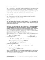
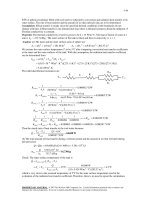
16-16 The convection heat transfer coefficient for a clothed person while walking in still air at a velocity
of 0.5 to 2 m/s is given by h = 8.6V 0.53 where V is in m/s and h is in W/m2.°C. The convection coefficients
in that range vary from 5.96 W/m2.°C at 0.5 m/s to 12.42 W/m2.°C at 2 m/s. Therefore, at low velocities,
the radiation and convection heat transfer coefficients are comparable in magnitude. But at high velocities,
the convection coefficient is much larger than the radiation heat transfer coefficient.
13.0
.
h = 8.6V0.53
12.0
2
m/s
W/m .°C
0.50
5.96
0.75
7.38
1.00
8.60
1.25
9.68
1.50
10.66
1.75
11.57
2.00
12.42
11.0
10.0
9.0
h
Velocity,
8.0
7.0
6.0
5.0
0.4
0.6
0.8
1.0
1.2
V
1.4
1.6
1.8
PROPRIETARY MATERIAL. © 2007 The McGraw-Hill Companies, Inc. Limited distribution permitted only to teachers and
educators for course preparation. If you are a student using this Manual, you are using it without permission.
2.0
16-4
16-17 A man wearing summer clothes feels comfortable in a room at 20°C. The room temperature at
which this man would feel thermally comfortable when unclothed is to be determined.
Assumptions 1 Steady conditions exist. 2 The latent heat loss from the person remains the same. 3 The heat
transfer coefficients remain the same. 4 The air in the room is still (there are no winds or running fans). 5
The surface areas of the clothed and unclothed person are the same.
Analysis At low air velocities, the convection heat transfer coefficient
for a standing man is given in Table 13-3 to be 4.0 W/m2.°C. The
radiation heat transfer coefficient at typical indoor conditions is 4.7
W/m2.°C. Therefore, the heat transfer coefficient for a standing person
for combined convection and radiation is
Troom= 20°C
Tskin= 33°C
hcombined = hconv + hrad = 4.0 + 4.7 = 8.7 W/m 2 .°C
The thermal resistance of the clothing is given to be
2
2
Rcloth = 1.1 clo = 1.1× 0.155 m .°C/W = 0.171 m .°C/W
Clothed
person
Noting that the surface area of an average man is 1.8 m2, the sensible
heat loss from this person when clothed is determined to be
A (T
− Tambient )
(1.8 m 2 )(33 − 20)°C
Q& sensible,clothed = s skin
=
= 82 W
1
1
2
Rcloth +
0.171 m .°C/W +
hcombined
8.7 W/m 2 .°C
From heat transfer point of view, taking the clothes off is equivalent to removing the clothing insulation or
setting Rcloth = 0. The heat transfer in this case can be expressed as
A (T
− Tambient ) (1.8 m 2 )(33 − Tambient )°C
Q& sensible,unclothed = s skin
=
1
1
hcombined
8.7 W/m 2 .°C
To maintain thermal comfort after taking the clothes off, the skin temperature of the person and the rate of
heat transfer from him must remain the same. Then setting the equation above equal to 82 W gives
Tambient = 27.8°C
Therefore, the air temperature needs to be raised from 22 to 27.8°C to ensure that the person will feel
comfortable in the room after he takes his clothes off. Note that the effect of clothing on latent heat is
assumed to be negligible in the solution above. We also assumed the surface area of the clothed and
unclothed person to be the same for simplicity, and these two effects should counteract each other.
PROPRIETARY MATERIAL. © 2007 The McGraw-Hill Companies, Inc. Limited distribution permitted only to teachers and
educators for course preparation. If you are a student using this Manual, you are using it without permission.
16-5
16-18E An average person produces 0.50 lbm of moisture while
taking a shower. The contribution of showers of a family of four to
the latent heat load of the air-conditioner per day is to be determined.
Moisture
0.5 lbm
Assumptions All the water vapor from the shower is condensed by
the air-conditioning system.
Properties The latent heat of vaporization of water is given to be 1050
Btu/lbm.
Analysis The amount of moisture produced per day is
m& vapor = ( Moisture produced per person)(No. of persons)
= (0.5 lbm/person)(4 persons/day) = 2 lbm/day
Then the latent heat load due to showers becomes
Q& latent = m& vapor h fg = ( 2 lbm/day)(1050 Btu/lbm) = 2100 Btu/day
16-19 There are 100 chickens in a breeding room. The rate of total heat generation and the rate of moisture
production in the room are to be determined.
Assumptions All the moisture from the chickens is
condensed by the air-conditioning system.
Properties The latent heat of vaporization of water is given
to be 2430 kJ/kg. The average metabolic rate of chicken
during normal activity is 10.2 W (3.78 W sensible and 6.42
W latent).
100
Chickens
10.2 W
Analysis The total rate of heat generation of the chickens
in the breeding room is
Q&
= q&
(No. of chickens)
gen, total
gen, total
= (10.2 W/chicken)(100 chickens) = 1020 W
The latent heat generated by the chicken and the rate of moisture production are
Q& gen, latent = q& gen, latent (No. of chickens)
= (6.42 W/chicken)(100 chickens) = 642 W
= 0.642 kW
m& moisture =
Q& gen, latent
h fg
=
0.642 kJ/s
= 0.000264 kg/s = 0.264 g/s
2430 kJ/kg
PROPRIETARY MATERIAL. © 2007 The McGraw-Hill Companies, Inc. Limited distribution permitted only to teachers and
educators for course preparation. If you are a student using this Manual, you are using it without permission.
16-6
16-20 Chilled air is to cool a room by removing the heat generated in a large insulated classroom by lights
and students. The required flow rate of air that needs to be supplied to the room is to be determined.
Assumptions 1 The moisture produced by the bodies leave the room as vapor without any condensing, and
thus the classroom has no latent heat load. 2 Heat gain through the walls and the roof is negligible.
Properties The specific heat of air at room temperature is 1.00 kJ/kg⋅°C (Table A-15). The average rate of
metabolic heat generation by a person sitting or doing light work is 115 W (70 W sensible, and 45 W
latent).
Analysis The rate of sensible heat generation by the
people in the room and the total rate of sensible internal
heat generation are
Return
air
Chilled
air
Q& gen, sensible = q& gen, sensible (No. of people)
Q& total, sensible
= (70 W/person)(90 persons) = 6300 W
= Q&
+ Q&
gen, sensible
lighting
= 6300 + 2000 = 8300 W
Then the required mass flow rate of chilled air becomes
Q& total, sensible
m& air =
c p ΔT
=
15°C
Lights
2 kW
25°C
90 Students
8.3 kJ/s
= 0.83 kg/s
(1.0 kJ/kg ⋅ °C)(25 − 15)°C
Discussion The latent heat will be removed by the air-conditioning system as the moisture condenses
outside the cooling coils.
16-21 A smoking lounge that can accommodate 15 smokers is considered. The required minimum flow rate
of air that needs to be supplied to the lounge is to be determined.
Assumptions Infiltration of air into the smoking lounge
is negligible.
V&air
Properties The minimum fresh air requirements for a
smoking lounge is 30 L/s per person (Table 16-2).
Analysis The required minimum flow rate of air that
needs to be supplied to the lounge is determined directly
from
V&
air
= V&
air per person ( No. of
persons)
= (30 L/s ⋅ person)(15 persons)
SMOKING
LOUNGE
15 smokers
3
= 450 L/s = 0.45 m /s
PROPRIETARY MATERIAL. © 2007 The McGraw-Hill Companies, Inc. Limited distribution permitted only to teachers and
educators for course preparation. If you are a student using this Manual, you are using it without permission.
16-7
16-22 The average mean radiation temperature during a cold day drops to 18°C. The required rise in the
indoor air temperature to maintain the same level of comfort in the same clothing is to be determined.
Assumptions 1 Air motion in the room is negligible. 2 The average clothing and exposed skin temperature
remains the same. 3 The latent heat loss from the body remains constant. 4 Heat transfer through the lungs
remain constant.
Properties The emissivity of the person is 0.95 (Table A-15).
The convection heat transfer coefficient from the body in still
air or air moving with a velocity under 0.2 m/s is hconv = 3.1
W/m2⋅°C (Table 16-3).
22°C
22°C
Analysis The total rate of heat transfer from the body is the
sum of the rates of heat loss by convection, radiation, and
evaporation,
Q& body, total = Q& sensible + Q& latent + Q& lungs
= (Q& conv + Q rad ) + Q& latent + Q& lungs
Noting that heat transfer from the skin by evaporation and from the lungs remains constant, the sum of the
convection and radiation heat transfer from the person must remain constant.
4
4
4
Q& sensible,old = hA(Ts − Tair, old ) + εAσ (Ts4 − Tsurr,
old ) = hA(Ts − 22) + 0.95 Aσ [(Ts + 273) − (22 + 273) ]
4
4
4
Q& sensible,new = hA(Ts − Tair, new ) + εAσ (Ts4 − Tsurr,
new ) = hA(Ts − Tair, new ) + 0.95 Aσ [(Ts + 273) − (18 + 273) ]
Setting the two relations above equal to each other, canceling the surface area A, and simplifying gives
− 22h − 0.95σ (22 + 273) 4 = − hTair, new − 0.95σ (18 + 273) 4
3.1(Tair, new − 22) + 0.95 × 5.67 × 10 −8 ( 2914 − 295 4 ) = 0
Solving for the new air temperature gives
Tair, new = 29.0°C
Therefore, the air temperature must be raised to 29°C to counteract the increase in heat transfer by
radiation.
PROPRIETARY MATERIAL. © 2007 The McGraw-Hill Companies, Inc. Limited distribution permitted only to teachers and
educators for course preparation. If you are a student using this Manual, you are using it without permission.
16-8
16-23 A car mechanic is working in a shop heated by radiant heaters in winter. The lowest ambient
temperature the worker can work in comfortably is to be determined.
Assumptions 1 The air motion in the room is negligible, and the mechanic is standing. 2 The average
clothing and exposed skin temperature of the mechanic is 33°C.
Properties The emissivity and absorptivity of the person is given to be 0.95. The convection heat transfer
coefficient from a standing body in still air or air moving with a velocity under 0.2 m/s is hconv = 4.0
W/m2⋅°C (Table 13-3).
Analysis The equivalent thermal resistance of clothing is
Rcloth = 0.7 clo = 0.7 × 0.155 m 2 .°C/W = 0.1085 m 2 .°C/W
Radiation from the heaters incident on the person and the rate
of sensible heat generation by the person are
Radiant
heater
Q& rad, incident = 0.05 × Q& rad, total = 0.05(4 kW) = 0.2 kW = 200 W
Q& gen, sensible = 0.5 × Q& gen, total = 0.5(350 W) = 175 W
Under steady conditions, and energy balance on the body can
be expressed as
E& in − E& out + E& gen = 0
Q& rad from heater − Q& conv + rad from body + Q& gen, sensible = 0
or
4
αQ& rad, incident − hconv As (Ts − Tsurr ) − εAsσ (Ts4 − Tsurr
) + Q& gen, sensible = 0
0.95(200 W) − (4.0 W/m 2 ⋅ K)(1.8 m 2 )(306 − Tsurr )
4
− 0.95(1.8 m 2 )(5.67 × 10⁻⁸ W/m 2 ⋅ K 4 )[(306 K) 4 − Tsurr
) + 175 W = 0
Solving the equation above gives
Tsurr = 284.8 K = 11.8°C
Therefore, the mechanic can work comfortably at temperatures as low as 12°C.
PROPRIETARY MATERIAL. © 2007 The McGraw-Hill Companies, Inc. Limited distribution permitted only to teachers and
educators for course preparation. If you are a student using this Manual, you are using it without permission.
16-9
Design conditions for Heating and Cooling
16-24C The extreme outdoor temperature under which a heating or cooling system must be able to
maintain a building at the indoor design conditions is called the outdoor design temperature. It differs from
the average winter temperature in that the average temperature represents the arithmetic average of the
hourly outdoors temperatures. The 97.5% winter design temperature ensures that the heating system will
provide thermal comfort 97.5 percent of the time, but may fail to do so during 2.5 percent of the time. The
99% winter design temperature, on the other hand, ensures that the heating system will provide thermal
comfort 99 percent of the time, but may fail to do so during 1 percent of the time in an average year.
16-25C Yes, it is possible for a city A to have a lower winter design temperature but a higher average
winter temperature than another city B. In that case, a house in city A will require a larger heating system,
but it will use less energy during a heating season.
16-26C The solar radiation has no effect on the design heating load in winter since the coldest outdoor
temperatures occur before sunrise, but it may reduce the annual energy consumption for heating
considerably. Similarly, the heat generated by people, lights, and appliances has no effect on the design
heating load in winter since the heating system should be able to meet the heating load of a house even
when there is no internal heat generation, but it will reduce the annual energy consumption for heating.
16-27C The solar radiation constitutes a major part of the cooling load, and thus it increases both the
design cooling load in summer and the annual energy consumption for cooling. Similarly, the heat
generated by people, lights, and appliances constitute a significant part of the cooling load, and thus it
increases both the design cooling load in summer and the annual energy consumption for cooling.
16-28C The moisture level of the outdoor air contributes to the latent heat load, and it affects the cooling
load in summer. This is because the humidity ratio of the outdoor air is higher than that of the indoor air in
summer, and the outdoor air that infiltrates into the building increases the amount of moisture inside. This
excess moisture must be removed by the air-conditioning system. The moisture level of the outdoor air, in
general, does affect the heating load in winter since the humidity ratio of the outdoor air is much lower
than that of the indoor air in winter, and the moisture production in the building is sufficient to keep the air
moist. However, in some cases, it may be necessary to add moisture to the indoor air. The heating load in
this case will increase because of the energy needed to vaporize the water.
16-29C The reason for different values of recommended design heat transfer coefficients for combined
convection and radiation on the outer surface of a building in summer and in winter is the wind velocity. In
winter, the wind velocity and thus the heat transfer coefficient is higher.
16-30C The sol-air temperature is defined as the equivalent outdoor air temperature that gives the same
rate of heat flow to a surface as would the combination of incident solar radiation, convection with the
ambient air, and radiation exchange with the sky and the surrounding surfaces. It is used to account for the
effect of solar radiation by considering the outside temperature to be higher by an amount equivalent to the
effect of solar radiation. The higher the solar absorptivity of the outer surface of a wall, the higher is the
amount of solar radiation absorption and thus the sol-air temperature.
16-31C Most of the solar energy absorbed by the walls of a brick house will be transferred to the outdoors
since the thermal resistance between the outer surface and the indoor air (the wall resistance + the
convection resistance on the inner surface) is much larger than the thermal resistance between the outer
surface and the outdoor air (just the convection resistance).
PROPRIETARY MATERIAL. © 2007 The McGraw-Hill Companies, Inc. Limited distribution permitted only to teachers and
educators for course preparation. If you are a student using this Manual, you are using it without permission.
16-10
16-32 The climatic conditions for major cities in the U.S. are listed in Table 16-4, and for the indicated
design levels we read
Winter:
Toutdoor = -19°C
Summer:
Toutdoor = 35°C
Twet-bulb = 23°C
(97.5 percent level)
(2.5 percent level)
Therefore, the heating and cooling systems in Lincoln, Nebraska for common applications should be sized
for these outdoor conditions. Note that when the wet-bulb and ambient temperatures are available, the
relative humidity and the humidity ratio of air can be determined from the psychrometric chart.
16-33 The climatic conditions for major cities in the U.S. are listed in Table 16-4, and for the indicated
design levels we read
Winter:
Toutdoor = -16°C
Summer:
Toutdoor = 37°C
Twet-bulb = 23°C
(99 percent level)
(2.5 percent level)
Therefore, the heating and cooling systems in Wichita, Kansas for common applications should be sized
for these outdoor conditions. Note that when the wet-bulb and ambient temperatures are available, the
relative humidity and the humidity ratio of air can be determined from the psychrometric chart.
PROPRIETARY MATERIAL. © 2007 The McGraw-Hill Companies, Inc. Limited distribution permitted only to teachers and
educators for course preparation. If you are a student using this Manual, you are using it without permission.
16-11
16-34 The south wall of a house is subjected to solar radiation at summer design conditions. The design
heat gain, the fraction of heat gain due to solar heating, and the fraction of solar radiation that is transferred
to the house are to be determined.
Assumptions 1 Steady conditions exist. 2 Thermal properties
of the wall and the heat transfer coefficients are constant.
Properties The overall heat transfer coefficient of the wall is
given to be 1.6 W/m2⋅°C.
Analysis (a) The house is located at 40°N latitude, and thus we
can use the sol-air temperature data directly from Table 16-7.
At 15:00 the tabulated air temperature is 35°C, which is
identical to the air temperature given in the problem.
Therefore, the sol-air temperature on the south wall in this case
is 43.6°C, and the heat gain through the wall is determined to
be
Brick
Air
space Plaster
Sun
22°C
35°C
Q& wall = UA(Tsol-air − Tinside ) = (1.6 W/m 2 ⋅ °C)(20 m 2 )(43.6 − 22)°C = 691.2 W
(b) Heat transfer is proportional to the temperature difference, and the overall temperature difference in this
case is 43.6 - 22 = 21.6°C. Also, the difference between the sol-air temperature and the ambient air
temperature is
ΔTsolar = Tsol-air − Tambient = 43.6 − 35 = 8.6°C
which is the equivalent temperature rise of the ambient air due to solar heating. The fraction of heat gain
due to solar heating is equal to the fraction of the solar temperature difference to the overall temperature
difference, and is determined to be
Solar fraction =
Q& wall,solar UAΔTsolar ΔTsolar
8.6°C
=
=
=
= 0.40 (or 40%)
&
Q wall,total UAΔTtotal ΔTtotal 21.6°C
Therefore, almost half of the heat gain through the west wall in this case is due to solar heating of the wall.
(c) The outer layer of the wall is made of red brick which is dark colored. Therefore, the value of α s / ho is
0.052 m2.°C/W. Then the fraction of incident solar energy transferred to the interior of the house is
determined directly from Eq. 16-20 to be
Solar fraction tranferred = U
αs
ho
= (1.6 W/m 2 ⋅ °C)(0.052 m 2 ⋅ °C/W ) = 0.0832
Discussion Less than 10 percent of the solar energy incident on the surface will be transferred to the house
in this case. Note that a glass wall would transmit about 10 times more energy into the house.
PROPRIETARY MATERIAL. © 2007 The McGraw-Hill Companies, Inc. Limited distribution permitted only to teachers and
educators for course preparation. If you are a student using this Manual, you are using it without permission.
16-12
16-35E The west wall of a house is subjected to solar radiation at summer design conditions. The design
heat gain and the fraction of heat gain due to solar heating are to be determined.
Assumptions 1 Steady conditions exist. 2 Thermal properties of the wall and the heat transfer coefficients
are constant.
Properties The overall heat transfer coefficient of the
wall is given to be 0.14 Btu/h⋅ft2⋅°F.
Analysis (a) The house is located at 40°N latitude,
and thus we can use the sol-air temperature data
directly from Table 16-7. At 15:00 the tabulated air
temperature is 94°F, which is 8°F higher than the air
temperature given in the problem. But we can still
use the data in that table provided that we subtract 8
°F from all temperatures. Therefore, the sol-air
temperature on the west wall in this case is 159 - 8 =
151°F, and the heat gain through the wall is
determined to be
Gypsum board
Concrete block
Brick
Sun
72°F
Q& wall
Tambient= 86°F
U=0.14 Btu/h.ft².°F
Q& wall = UA(Tsol-air − Tinside ) = (0.14 Btu/h ⋅ ft 2 ⋅ °F)(150 ×12 ft 2 )(151 − 72)°F = 19,908 Btu/h
(b) Heat transfer is proportional to the temperature difference, and the overall temperature difference in this
case is 151 - 72 = 79°F. Also, the difference between the sol-air temperature and the ambient air
temperature is
ΔTsolar = Tsol-air − Tambient = 151 − 86 = 65°F
which is the equivalent temperature rise of the ambient air due to solar heating. The fraction of heat gain
due to solar heating is equal to the ratio of the solar temperature difference to the overall temperature
difference, and is determined to be
Solar fraction =
Q& wall,solar UAΔTsolar ΔTsolar 65°F
=
=
=
= 0.823 (or 82.3%)
Q& wall,total UAΔTtotal ΔTtotal 79°F
Therefore, almost the entire heat gain through the west wall in this case is due to solar heating of the wall.
PROPRIETARY MATERIAL. © 2007 The McGraw-Hill Companies, Inc. Limited distribution permitted only to teachers and
educators for course preparation. If you are a student using this Manual, you are using it without permission.
16-13
16-36 The roof of a house is subjected to solar radiation at summer design conditions. The design heat gain
and the fraction of heat gain due to solar heating are to be determined.
Assumptions 1 Steady conditions exist. 2 Thermal properties of the wall and the heat transfer coefficients
are constant.
Properties The overall heat transfer coefficient of the roof is given to be 1.8 W/m2⋅°C.
Analysis (a) The house is located at 40°N latitude, and
thus we can use the sol-air temperature data directly
from Table 16-7. At 16:00 the tabulated air temperature
is 34.7°C, which is 4.7°C higher than the air
temperature given in the problem. But we can still use
the data in that table provided that we subtract 4.7°C
from all temperatures. Therefore, the sol-air temperature
on the roof in this case is 42.7 - 4.7 = 38.0°C, and the
heat gain through the roof is determined to be
Q&
= UA(T
−T
)
roof
sol -air
2
Sun
30°C
White
Concrete
22°C
inside
Plaster
2
= (1.8 W/m ⋅ °C)(150 m )(38 − 22)°C = 4320 W
(b) Heat transfer is proportional to the temperature
difference, and the overall temperature difference in this
case is 38 - 22 = 16°C. Also, the difference between the
sol-air temperature and the ambient air temperature is
ΔTsolar = Tsol-air − Tambient = 38 − 30 = 8°C
which is the equivalent temperature rise of the ambient air due to solar heating. The fraction of heat gain
due to solar heating is equal to the ratio of the solar temperature difference to the overall temperature
difference, and is determined to be
Solar fraction =
Q& wall,solar UAΔTsolar ΔTsolar
8°C
=
=
=
= 0.50 (or 50%)
&
Q wall,total UAΔTtotal ΔTtotal 16°C
Therefore, half of the heat gain through the roof in this case is due to solar heating of the roof.
PROPRIETARY MATERIAL. © 2007 The McGraw-Hill Companies, Inc. Limited distribution permitted only to teachers and
educators for course preparation. If you are a student using this Manual, you are using it without permission.
16-14
Heat Gain from People, Lights, and Appliances
16-37C The heat given off by people in a concert hall is an important consideration in the sizing of the
air-conditioning system for that building because of the high density of people in the hall, and the heat
generation from the people contributes a significant amount to the cooling load.
16-38C By replacing the incandescent lamps of a building by high-efficiency fluorescent lamps, (a) the
design cooling load will decrease, (b) annual energy consumption for cooling will also decrease, and (c)
annual energy consumption for heating for the building will increase since fluorescent lamps generate
much less heat than incandescent lamps for the same light output.
16-39C It is usually a good idea to replace incandescent light bulbs by compact fluorescent bulbs that may
cost 40 times as much to purchase since incandescent lights waste energy by (1) consuming more
electricity for the same amount of lighting, and (2) making the cooling system work harder and longer to
remove the heat given off.
16-40C The motors and appliances in a building generate heat, and thus (a) they increase the design
cooling load, (b) they increase the annual energy consumption for cooling, and (c) they reduce the annual
energy consumption for heating of the building.
16-41C The motor efficiency ηmotor is defined as the ratio of the shaft power delivered to the electrical
power consumed by the motor. The higher the motor efficiency, the lower is the amount of heat generated
by the motor. Therefore, high efficiency motors decrease the design cooling load of a building and the
annual energy consumption for cooling.
16-42C The heat generated by a hooded range in a kitchen with a powerful fan that exhausts all the air
heated and humidified by the range still needs to be considered in the determination of the cooling load of
the kitchen although all the heated air is exhausted since part of the energy (32% of it) is radiated to the
surroundings from the hot surfaces.
PROPRIETARY MATERIAL. © 2007 The McGraw-Hill Companies, Inc. Limited distribution permitted only to teachers and
educators for course preparation. If you are a student using this Manual, you are using it without permission.
16-15
16-43 A hooded electric open burner and a gas burner are considered. The amount of the electrical energy
used directly for cooking, the cost of energy per “utilized” kWh, and the contribution of this burner to the
design cooling load are to be determined.
Analysis The efficiency of the electric heater is given to be 78 percent.
Therefore, a burner that consumes 3-kW of electrical energy will supply
Q& utilized = (Energy input) × (Efficiency) = (3 kW)(0.73) = 2.19 kW
of useful energy. The unit cost of utilized energy is inversely proportional to
the efficiency, and is determined from
Cost of utilized energy =
Cost of energy input $0.09 / kWh
=
= $0.123/kWh
Efficiency
0.73
The design heat gain from a hooded appliance is taken to be 32% of the half of its
rated energy consumption, and is determined to be
Q& hooded appliance = 0.5 × 0.32Q& appliance, input = 0.5 × 0.32 × (3 kW ) = 0.48 kW (electric burner)
Noting that the efficiency of a gas burner is 38 percent, the energy input to a gas burner that supplies
utilized energy at the same rate (2.19 kW) is
Q& utilized
2.19 kW
Q& input, gas =
=
= 5.76 kW (= 19,660 Btu/h)
Efficiency
0.38
since 1 kW = 3412 Btu/h. Therefore, a gas burner should have a rating of at least 19,660 Btu/h to perform
as well as the electric unit.
Noting that 1 therm = 29.3 kWh, the unit cost of utilized energy in the case of gas burner is
determined the same way to be
Cost of utilized energy =
Cost of energy input $1.10 /( 29.3 kWh)
=
= $0.099/kWh
Efficiency
0.38
which is about 20 percent less than the unit cost of utilized electricity. The design heat gain from this
hooded gas burner is determined similarly to be
Q&
= 0.5 × 0.32Q&
= 0.5 × 0.32 × (5.76 kW ) = 0.922 kW (gas burner)
unhooded appliance
appliance, input
which is almost twice as much as that of the electric burner. Therefore, a hooded gas appliance will
contribute more to the heat gain than a comparable electric appliance.
PROPRIETARY MATERIAL. © 2007 The McGraw-Hill Companies, Inc. Limited distribution permitted only to teachers and
educators for course preparation. If you are a student using this Manual, you are using it without permission.
16-16
16-44 Several people are working out in an exercise room. The rate of heat gain from people and the
equipment, and the fraction of that heat in the latent form are to be determined.
Analysis The 8 weight lifting machines do not have any motors, and thus they do not contribute to the
internal heat gain directly. The usage factors of the motors of the treadmills are taken to be unity since they
are used constantly during peak periods. Noting that 1 hp = 746 W, the total heat generated by the motors
is
Q& motors = ( No. of motors ) × W& motor × f load × f usage / η motor = 4 × ( 2.5 × 746 W) × 0.70 × 1.0/0.77 = 6782 W
The average rate of heat dissipated by people in an exercise room is
given in Table 16-8 to be 525 W, of which 315 W is in latent form.
Therefore, the heat gain from 14 people is
Q&
= ( No. of people) × Q&
= 14 × (525 W) = 7350 W
people
person
Then the total rate of heat gain (or the internal heat load) of the
exercise room during peak period becomes
Q&
= Q&
+ Q&
= 6782 + 7350 = 14,132 W
total
motors
people
The entire heat given off by the motors is in sensible form. Therefore,
the latent heat gain is due to people only, which is determined to be
Q&
= ( No. of people) × Q&
= 14 × (315 W) = 4410 W
latent
latent, per person
The remaining 14,132 - 4410 = 9722 W of heat gain is in the sensible form.
16-45 A worn out standard motor is replaced by a high efficiency one. The reduction in the internal heat
gain due to higher efficiency under full load conditions is to be determined.
Assumptions 1 The motor and the equipment driven by the motor are in
the same room. 2 The motor operates at full load so that fload = 1.
Analysis The heat generated by a motor is due to its inefficiency, and the
difference between the heat generated by two motors that deliver the
same shaft power is simply the difference between the electric power
drawn by the motors,
/η
W&
= W&
= (75 × 746 W)/0.91 = 61,484 W
in, electric, standard
shaft
motor
W& in, electric, efficient = W& shaft / η motor = (75 × 746 W)/0.954 = 58,648 W
Q&
91%
efficient
Motor
75 hp
Then the reduction in heat generation becomes
Q& reduction = W& in, electric, standard − W& in, electric, efficient = 61,484 − 58,648 = 2836 W
PROPRIETARY MATERIAL. © 2007 The McGraw-Hill Companies, Inc. Limited distribution permitted only to teachers and
educators for course preparation. If you are a student using this Manual, you are using it without permission.
16-17
16-46 An electric hot plate and a gas hot plate are considered. For the same amount of “utilized” energy,
the ratio of internal heat generated by gas hot plates to that by electric ones is to be determined.
Assumptions Hot plates are not hooded and thus the entire
energy they consume is dissipated to the room they are in.
23%
48%
Analysis The utilized energy can be expressed in terms of
the energy input and the efficiency as
E&
= (Energy input) × (Efficiency)
utilized
= E& in ×η
→ E& in = E& utilized / η
Noting that the utilized energy is the same for both the
electric and gas hot plates, the ratio of internal heat
generated by gas hot plates to that by electric ones is
determined to be
Gas
&
&
E in, gas
E utilized / η gas
η
0.48
=
= electric =
= 2.07
Ratio of heat generation =
&
&
0.23
η gas
E in, electric
E utilized / η electric
Electric
Therefore, the gas hot plate will contribute twice as much to the internal heat gain of the room.
16-47 A classroom has 40 students, one instructor, and 18 fluorescent light bulbs. The rate of internal heat
generation in this classroom is to be determined.
Assumptions 1 There is a mix of men, women, and children in the classroom. 2 The amount of light (and
thus energy) leaving the room through the windows is negligible.
Properties The average rate of heat generation from people seated in a room/office is 115 W (Table 16-8).
Analysis The amount of heat dissipated by the lamps is equal to the
amount of electrical energy consumed by the lamps, including the 10%
additional electricity consumed by the ballasts. Therefore,
Q& lighting = (Energy consumed per lamp) × (No. of lamps)
= (40 W)(1.1)(18) = 792 W
&
Q people = ( No. of people) × Q& person = 41× (115 W) = 4715 W
40 Students
Classroom
Then the total rate of heat gain (or the internal heat load) of the
classroom from the lights and people become
Q&
= Q&
+ Q&
= 792 + 4715 = 5507 W
total
lighting
people
PROPRIETARY MATERIAL. © 2007 The McGraw-Hill Companies, Inc. Limited distribution permitted only to teachers and
educators for course preparation. If you are a student using this Manual, you are using it without permission.
16-18
16-48 An electric car is powered by an electric motor mounted in the engine compartment. The rate of heat
supply by the motor to the engine compartment at full load conditions is to be determined.
Assumptions The motor operates at full load so that fload = 1.
Analysis The heat generated by a motor is due to its
inefficiency, and the heat generated by a motor is equal to
the difference between the electrical energy it consumes
and the shaft power it delivers,
Electric
Motor
η= 88%
W& in, electric = W& shaft / η motor = (60 hp)/0.88 = 68.18 hp
Q& generation = W& in, electric − W& shaft out
Heat
= 68.18 − 60 = 8.18 hp = 6.10 kW
since 1 hp = 0.746 kW.
Discussion The motor will supply as much heat to the compartment as a 6.1 kW resistance heater.
16-49 A room is cooled by circulating chilled water, and the air is circulated through the heat exchanger by
a fan. The contribution of the fan-motor assembly to the cooling load of the room is to be determined.
Assumptions The fan motor operates at full load so that fload = 1.
Analysis The entire electrical energy consumed by the
motor, including the shaft power delivered to the fan, is
eventually dissipated as heat. Therefore, the contribution of
the fan-motor assembly to the cooling load of the room is
equal to the electrical energy it consumes,
Q&
= W&
= W&
/η
internal generation
in, electric
shaft
motor
= (0.25 hp)/0.54 = 0.463 hp = 345 W
ROOM
η = 0.54
Q&
91%
0.25 hp
Motor 0.25 hp
since 1 hp = 746 W.
PROPRIETARY MATERIAL. © 2007 The McGraw-Hill Companies, Inc. Limited distribution permitted only to teachers and
educators for course preparation. If you are a student using this Manual, you are using it without permission.
16-19
16-50 An office that is being cooled adequately by a 12,000 Btu/h window air-conditioner is converted to a
computer room. The number of additional air-conditioners that need to be installed is to be determined.
Assumptions 1 The computer are operated by 4 adult men. 2 The computers consume 40 percent of their
rated power at any given time.
Properties The average rate of heat generation from a man seated in a room/office is 130 W (Table 16-8).
Analysis The amount of heat dissipated by the computers is
equal to the amount of electrical energy they consume.
Therefore,
Q&
= (Rated power) × (Usage factor)
computers
Q& people
Q& total
= (3.5 kW)(0.4) = 1.4 kW
= ( No. of people) × Q&
person
= 4 × (130 W) = 520 W
= Q&
+ Q&
computers
3.5 kW
Computers
A/C
12,000
Btu/h
people
= 1400 + 520 = 1920 W = 6551 Btu/h
since 1 W = 3.412 Btu/h. Then noting that each available
air conditioner provides 4,000 Btu/h cooling, the number of
air-conditioners needed becomes
No. of air conditioners =
Cooling load
6551 Btu/h
=
= 1.6 ≈ 2 Air conditioners
Cooling capacity of A/C 4000 Btu/h
16-51 A restaurant purchases a new 8-kW electric range for its kitchen. The increase in the design cooling
load is to be determined for the cases of hooded and unhooded range.
68%
Assumptions 1 The contribution of an appliance to the design
Hot
and
humid
cooling is half of its rated power. 2 The hood of an appliance
removes all the heated air and moisture generated, except the
radiation heat that constitutes 38 percent of the heat generated.
Analysis The design cooling load due to an unhooded range is
half of its rated power, and the design cooling of a hooded
range is half of the radiation component of heat dissipation,
which is taken to be 38 percent. Then the increase in the design
cooling load for both cases becomes
32%
Radiation
Q& unhooded appliance = 0.5 × Q& appliance, input = 0.5 × (8 kW ) = 4 kW
Q& hooded appliance = 0.5 × 0.32Q& appliance, input = 0.5 × 0.32 × (8 kW ) = 1.28 kW
PROPRIETARY MATERIAL. © 2007 The McGraw-Hill Companies, Inc. Limited distribution permitted only to teachers and
educators for course preparation. If you are a student using this Manual, you are using it without permission.
16-20
16-52 A department store expects to have 95 people at peak times in summer. The contribution of people to
the sensible, latent, and total cooling load of the store is to be determined.
Assumptions There is a mix of men, women, and children in the classroom.
Properties The average rate of heat generation from people in a
shopping center is 130 W, and 75 W of it is in sensible form and
55 W in latent form (Table 16-8).
Analysis The contribution of people to the sensible, latent, and
total cooling load of the store are
Q&
= ( No. of people) × Q&
= 95 × (130 W) = 12,350 W
people, total
person, total
Q& people, sensible = ( No. of people) × Q& person, sensible = 95 × (70 W) = 7125 W
Q& people
DEPARMENT
STORE
80 Customers
15 Employees
Q& people, latent = ( No. of people) × Q& person, latent = 95 × (35 W) = 5225 W
16-53E There are 500 people in a movie theater in winter. It is to be determined if the theater needs to be
heated or cooled.
Assumptions There is a mix of men, women, and children in the classroom.
Properties The average rate of heat generation from people in a movie theater is 105 W, and 70 W of it is
in sensible form and 35 W in latent form (Table 16-8).
Analysis Noting that only the sensible heat from a
person contributes to the heating load of a building, the
contribution of people to the heating of the building is
150,000 Btu/h
Q& people, sensible = ( No. of people) × Q& person, sensible
= 500 × (70 W) = 35,000 W
= 119,420 Btu/h
since 1 W = 3.412 Btu/h. The building needs to be
heated since the heat gain from people is less than the
rate of heat loss of 150,000 Btu/h from the building.
MOVIE
THEATER
500 people
PROPRIETARY MATERIAL. © 2007 The McGraw-Hill Companies, Inc. Limited distribution permitted only to teachers and
educators for course preparation. If you are a student using this Manual, you are using it without permission.
16-21
Heat Transfer through the Walls and Roofs
16-54C The R-value of a wall is the thermal resistance of the wall per unit surface area. It is the same as
the unit thermal resistance of the wall. It is the inverse of the U-factor of the wall, R = 1/U.
16-55C The effective emissivity for a plane-parallel air space is the “equivalent” emissivity of one surface
for use in the relation Q& rad = ε effectiveσA(T24 − T14 ) that results in the same rate of radiation heat transfer
between the two surfaces across the air space. It is determined from
1
ε effective
=
1
ε1
+
1
ε2
−1
where ε1 and ε2 are the emissivities of the surfaces of the air space. When the effective emissivity is
known, the radiation heat transfer through the air space is determined from the Q& rad relation above.
16-56C The unit thermal resistances (R-value) of both 40-mm and 90-mm vertical air spaces are given to
be the same, which implies that more than doubling the thickness of air space in a wall has no effect on
heat transfer through the wall. This is not surprising since the convection currents that set in in the thicker
air space offset any additional resistance due to a thicker air space.
16-57C Radiant barriers are highly reflective materials that minimize the radiation heat transfer between
surfaces. Highly reflective materials such as aluminum foil or aluminum coated paper are suitable for use
as radiant barriers. Yes, it is worthwhile to use radiant barriers in the attics of homes by covering at least
one side of the attic (the roof or the ceiling side) since they reduce radiation heat transfer between the
ceiling and the roof considerably.
16-58C The roof of a house whose attic space is ventilated effectively so that the air temperature in the
attic is the same as the ambient air temperature at all times will still have an effect on heat transfer through
the ceiling since the roof in this case will act as a radiation shield, and reduce heat transfer by radiation.
PROPRIETARY MATERIAL. © 2007 The McGraw-Hill Companies, Inc. Limited distribution permitted only to teachers and
educators for course preparation. If you are a student using this Manual, you are using it without permission.
16-22
16-59 The R-value and the U-factor of a wood frame wall are to be determined.
Assumptions 1 Steady operating conditions exist. 2 Heat transfer through the wall is one-dimensional. 3
Thermal properties of the wall and the heat transfer coefficients are constant.
Properties The R-values of different materials are given in Table 16-10.
Analysis The schematic of the wall as well as the different elements used in its construction are shown
below. Heat transfer through the insulation and through the studs will meet different resistances, and thus
we need to analyze the thermal resistance for each path separately. Once the unit thermal resistances and
the U-factors for the insulation and stud sections are available, the overall average thermal resistance for
the entire wall can be determined from
Roverall = 1/Uoverall
where Uoverall = (Ufarea )insulation + (Ufarea )stud
and the value of the area fraction farea is 0.80 for insulation section and 0.20 for stud section since the
headers that constitute a small part of the wall are to be treated as studs. Using the available R-values from
Table 16-10 and calculating others, the total R-values for each section is determined in the table below.
R-value, m2.°C/W
Construction
Between
studs
At studs
1. Outside surface, 12 km/h wind
0.044
0.044
2. Wood bevel lapped siding
0.14
0.14
3. Fiberboard sheathing, 13 mm
0.23
0.23
4a. Mineral fiber insulation, 140 mm
3.696
--
4b. Wood stud, 38 mm by 140 mm
--
0.98
5. Gypsum wallboard, 13 mm
0.079
0.079
6. Inside surface, still air
0.12
0.12
Total unit thermal resistance of each section, R (in m2.°C/W)
4b
6
4a
3
5
1
4.309
1.593
The U-factor of each section, U = 1/R, in W/m .°C
0.232
0.628
Area fraction of each section, farea
0.80
2
0.20
2
Overall U-factor, U = Σfarea,iUi = 0.80×0.232+0.20×0.628
0.311 W/m .°C
Overall unit thermal resistance, R = 1/U
3.213 m2.°C/W
Therefore, the R-value and U-factor of the wall are R = 3.213 m2.°C/W and U = 0.311 W/m2.°C.
PROPRIETARY MATERIAL. © 2007 The McGraw-Hill Companies, Inc. Limited distribution permitted only to teachers and
educators for course preparation. If you are a student using this Manual, you are using it without permission.
16-23
16-60 The change in the R-value of a wood frame wall due to replacing fiberwood sheathing in the wall by
rigid foam sheathing is to be determined.
Assumptions 1 Steady operating conditions exist. 2 Heat transfer through the wall is one-dimensional. 3
Thermal properties of the wall and the heat transfer coefficients are constant.
Properties The R-values of different materials are given in Table 16-10.
Analysis The schematic of the wall as well as the different elements used in its construction are shown
below. Heat transfer through the insulation and through the studs will meet different resistances, and thus
we need to analyze the thermal resistance for each path separately. Once the unit thermal resistances and
the U-factors for the insulation and stud sections are available, the overall average thermal resistance for
the entire wall can be determined from
Roverall = 1/Uoverall
where Uoverall = (Ufarea )insulation + (Ufarea )stud
and the value of the area fraction farea is 0.80 for insulation section and 0.20 for stud section since the
headers that constitute a small part of the wall are to be treated as studs. Using the available R-values from
Table 16-10 and calculating others, the total R-values for each section of the existing wall is determined in
the table below.
4b
R -value, m2.°C/W
Construction
Between
studs
At studs
1. Outside surface, 12 km/h wind
0.044
0.044
2. Wood bevel lapped siding
0.14
0.14
3. Rigid foam, 25 mm
0.98
0.98
4a. Mineral fiber insulation, 140 mm
3.696
--
4b. Wood stud, 38 mm by 140 mm
--
0.98
5. Gypsum wallboard, 13 mm
0.079
0.079
6. Inside surface, still air
0.12
0.12
Total unit thermal resistance of each section, R (in m2.°C/W)
3
1
5.059
2.343
The U-factor of each section, U = 1/R, in W/m .°C
0.198
0.426
Area fraction of each section, farea
0.80
0.20
Overall U-factor, U = Σfarea,iUi = 0.80×0.232+0.20×0.628
0.2436 W/m2.°C
Overall unit thermal resistance, R = 1/U
4.105 m2.°C/W
2
4a
5
2
The R-value of the existing wall is R = 3.213 m2.°C/W. Then the change in the R-value becomes
% Change =
ΔR − value
4.105 − 3.213
=
= 0.217 (or 21.7%)
R − value, old
4.105
PROPRIETARY MATERIAL. © 2007 The McGraw-Hill Companies, Inc. Limited distribution permitted only to teachers and
educators for course preparation. If you are a student using this Manual, you are using it without permission.
6
16-24
16-61E The R-value and the U-factor of a masonry cavity wall are to be determined.
Assumptions 1 Steady operating conditions exist. 2 Heat transfer through the wall is one-dimensional. 3
Thermal properties of the wall and the heat transfer coefficients are constant.
Properties The R-values of different materials are given in Table 16-10.
Analysis The schematic of the wall as well as the different elements used in its construction are shown
below. Heat transfer through the air space and through the studs will meet different resistances, and thus
we need to analyze the thermal resistance for each path separately. Once the unit thermal resistances and
the U-factors for the air space and stud sections are available, the overall average thermal resistance for the
entire wall can be determined from
Roverall = 1/Uoverall
where Uoverall = (Ufarea )air space +
(Ufarea )stud
and the value of the area fraction farea is 0.80 for air space and 0.20 for the ferrings and similar structures.
Using the available R-values from Table 16-10 and calculating others, the total R-values for each section of
the existing wall is determined in the table below.
R-value, h.ft2.°F/Btu
Construction
Between
furring
At
furring
1. Outside surface, 15 mph wind
0.17
0.17
2. Face brick, 4 in
0.43
0.43
3. Cement mortar, 0.5 in
0.10
0.10
4. Concrete block, 4-in
1.51
1.51
5a. Air space, 3/4-in, nonreflective
2.91
--
5b. Nominal 1 × 3 vertical furring
--
0.94
6. Gypsum wallboard, 0.5 in
0.45
0.45
7. Inside surface, still air
0.68
0.68
Total unit thermal resistance of each section, R
5b
6
1
2
6.25
4.28
The U-factor of each section, U = 1/R, in Btu/h.ft .°F
0.160
0.234
Area fraction of each section, farea
0.80
0.20
Overall U-factor, U = Σfarea,iUi = 0.80×0.160+0.20×0.234
0.175 Btu/h.ft2.°F
Overall unit thermal resistance, R = 1/U
5.72 h.ft2.°F/Btu
2
3
4
7
5a
Therefore, the overall unit thermal resistance of the wall is R = 5.72 h.ft2.°F/Btu and the overall U-factor is
U = 0.175 Btu/h.ft2.°F. These values account for the effects of the vertical ferring.
PROPRIETARY MATERIAL. © 2007 The McGraw-Hill Companies, Inc. Limited distribution permitted only to teachers and
educators for course preparation. If you are a student using this Manual, you are using it without permission.
16-25
16-62 The winter R-value and the U-factor of a flat ceiling with an air space are to be determined for the
cases of air space with reflective and nonreflective surfaces.
Assumptions 1 Steady operating conditions exist. 2 Heat transfer through the ceiling is one-dimensional. 3
Thermal properties of the ceiling and the heat transfer coefficients are constant.
Properties The R-values of different materials are given in Table 16-10. The R-values of different air
layers are given in Table 16-13.
Analysis The schematic of the ceiling as well as the different elements used in its construction are shown
below. Heat transfer through the air space and through the studs will meet different resistances, and thus
we need to analyze the thermal resistance for each path separately. Once the unit thermal resistances and
the U-factors for the air space and stud sections are available, the overall average thermal resistance for the
entire wall can be determined from
Roverall = 1/Uoverall where Uoverall = (Ufarea )air space + (Ufarea )stud
and the value of the area fraction farea is 0.82 for air space and 0.18 for stud section since the headers
which constitute a small part of the wall are to be treated as studs.
1
1
(a) Nonreflective surfaces, ε 1 = ε 2 = 0.9 and thus ε effective =
=
= 0.82
1 / ε 1 + 1 / ε 2 − 1 1 / 0.9 + 1 / 0.9 − 1
Construction
1. Still air above ceiling
2. Linoleum (R = 0.009 m2.°C/W)
3. Felt (R = 0.011 m2.°C/W)
4. Plywood, 13 mm
5. Wood subfloor (R = 0.166 m2.°C/W)
6a. Air space, 90 mm, nonreflective
6b. Wood stud, 38 mm by 90 mm
7. Gypsum wallboard, 13 mm
8. Still air below ceiling
R -value, m2.°C/W
Between At studs
studs
0.12
0.044
0.009
0.14
0.011
0.23
0.11
0.166
0.16
----0.63
0.079
0.079
0.12
0.12
1
2
3
4
5
6
7
8
Total unit thermal resistance of each section, R (in m2.°C/W)
The U-factor of each section, U = 1/R, in W/m2.°C
Area fraction of each section, farea
Overall U-factor, U = Σfarea,iUi = 0.82×1.290+0.18×0.805
Overall unit thermal resistance, R = 1/U
(b) One-reflective surface, ε 1 = 0.05 and ε 2 = 0.9 → ε effective
0.775
1.243
1.290
0.805
0.82
0.18
2
1.203 W/m .°C
0.831 m2.°C/W
1
1
=
=
= 0.05
1 / ε 1 + 1 / ε 2 − 1 1 / 0.05 + 1 / 0.9 − 1
In this case we replace item 6a from 0.16 to 0.47 m2.°C/W. It gives R = 1.085 m2.°C/W and U = 0.922 W/
m2.°C for the air space. Then,
Overall U-factor, U = Σfarea,iUi = 0.82×1.085+0.18×0.805
1.035 W/m2.°C
Overall unit thermal resistance, R = 1/U
0.967 m2.°C/W
1
1
(c) Two-reflective surface, ε 1 = ε 2 = 0.05 → ε effective =
=
= 0.03
1 / ε 1 + 1 / ε 2 − 1 1 / 0.05 + 1 / 0.05 − 1
In this case we replace item 6a from 0.16 to 0.49 m2.°C/W. It gives R = 1.105 m2.°C/W and U = 0.905 W/
m2.°C for the air space. Then,
Overall U-factor, U = Σfarea,iUi = 0.82×1.105+0.18×0.805
1.051 W/m2.°C
Overall unit thermal resistance, R = 1/U
0.951 m2.°C/W
PROPRIETARY MATERIAL. © 2007 The McGraw-Hill Companies, Inc. Limited distribution permitted only to teachers and
educators for course preparation. If you are a student using this Manual, you are using it without permission.