truyền thông Đồng hồ nhiệt độ E5CC với PLC
Bạn đang xem bản rút gọn của tài liệu. Xem và tải ngay bản đầy đủ của tài liệu tại đây (6.84 MB, 186 trang )
1
Communications
Methods
2
CompoWay/F Communications Procedures
Digital Temperature Controllers
3
Communications
Data for CompoWay/F
4
Communications Manual
E5@C
Modbus Communications Procedure
5
Communications
Data for Modbus
6
Programless
Communications
7
Component
Communications
A
Appendices
I
Index
H175-E1-08
Preface
Preface
This Communications Manual describes the communications capabilities supported by the E5@C Digital Controllers.
Read and understand this manual before using communications with the E5@C Digital Controllers and
be sure you are performing communications correctly.
Keep this manual in a safe location where it will be available when needed.
© OMRON, 2011
All rights reserved. No part of this publication may be reproduced, stored in a retrieval system or transmitted, in any form,
or by any means, mechanical, electronic, photocopying, recording, or otherwise, without the prior written permission of
OMRON.
No patent liability is assumed with respect to the use of the information contained herein. Moreover, because OMRON is
constantly striving to improve its high-quality products, the information contained in this manual is subject to change
without notice. Every precaution has been taken in the preparation of this manual. Nevertheless, OMRON assumes no
responsibility for errors or omissions. Neither is any liability assumed for damages resulting from the use of the information
contained in this publication.
E5@C Digital Temperature Controllers Communications Manual (H175)
1
Terms and Conditions Agreement
Terms and Conditions Agreement
Warranty, Limitations of Liability
Warranties
z Exclusive Warranty
Omron’s exclusive warranty is that the Products will be free from defects in materials and
workmanship for a period of twelve months from the date of sale by Omron (or such other period
expressed in writing by Omron). Omron disclaims all other warranties, express or implied.
z Limitations
OMRON MAKES NO WARRANTY OR REPRESENTATION, EXPRESS OR IMPLIED, ABOUT
NON-INFRINGEMENT, MERCHANTABILITY OR FITNESS FOR A PARTICULAR PURPOSE OF
THE PRODUCTS. BUYER ACKNOWLEDGES THAT IT ALONE HAS DETERMINED THAT THE
PRODUCTS WILL SUITABLY MEET THE REQUIREMENTS OF THEIR INTENDED USE.
Omron further disclaims all warranties and responsibility of any type for claims or expenses based
on infringement by the Products or otherwise of any intellectual property right.
z Buyer Remedy
Omron’s sole obligation hereunder shall be, at Omron’s election, to (i) replace (in the form originally
shipped with Buyer responsible for labor charges for removal or replacement thereof) the
non-complying Product, (ii) repair the non-complying Product, or (iii) repay or credit Buyer an
amount equal to the purchase price of the non-complying Product; provided that in no event shall
Omron be responsible for warranty, repair, indemnity or any other claims or expenses regarding the
Products unless Omron’s analysis confirms that the Products were properly handled, stored,
installed and maintained and not subject to contamination, abuse, misuse or inappropriate
modification. Return of any Products by Buyer must be approved in writing by Omron before
shipment. Omron Companies shall not be liable for the suitability or unsuitability or the results from
the use of Products in combination with any electrical or electronic components, circuits, system
assemblies or any other materials or substances or environments. Any advice, recommendations or
information given orally or in writing, are not to be construed as an amendment or addition to the
above warranty.
See or contact your Omron representative for published information.
Limitation on Liability; Etc
OMRON COMPANIES SHALL NOT BE LIABLE FOR SPECIAL, INDIRECT, INCIDENTAL, OR CONSEQUENTIAL DAMAGES, LOSS OF PROFITS OR PRODUCTION OR COMMERCIAL LOSS IN ANY
WAY CONNECTED WITH THE PRODUCTS, WHETHER SUCH CLAIM IS BASED IN CONTRACT,
WARRANTY, NEGLIGENCE OR STRICT LIABILITY.
Further, in no event shall liability of Omron Companies exceed the individual price of the Product on
which liability is asserted.
2
E5@C Digital Temperature Controllers Communications Manual (H175)
Terms and Conditions Agreement
Application Considerations
Suitability of Use
Omron Companies shall not be responsible for conformity with any standards, codes or regulations
which apply to the combination of the Product in the Buyer’s application or use of the Product. At
Buyer’s request, Omron will provide applicable third party certification documents identifying ratings
and limitations of use which apply to the Product. This information by itself is not sufficient for a complete determination of the suitability of the Product in combination with the end product, machine, system, or other application or use. Buyer shall be solely responsible for determining appropriateness of
the particular Product with respect to Buyer’s application, product or system. Buyer shall take application responsibility in all cases.
NEVER USE THE PRODUCT FOR AN APPLICATION INVOLVING SERIOUS RISK TO LIFE OR
PROPERTY WITHOUT ENSURING THAT THE SYSTEM AS A WHOLE HAS BEEN DESIGNED TO
ADDRESS THE RISKS, AND THAT THE OMRON PRODUCT(S) IS PROPERLY RATED AND
INSTALLED FOR THE INTENDED USE WITHIN THE OVERALL EQUIPMENT OR SYSTEM.
Programmable Products
Omron Companies shall not be responsible for the user’s programming of a programmable Product, or
any consequence thereof.
Disclaimers
Performance Data
Data presented in Omron Company websites, catalogs and other materials is provided as a guide for
the user in determining suitability and does not constitute a warranty. It may represent the result of
Omron’s test conditions, and the user must correlate it to actual application requirements. Actual performance is subject to the Omron’s Warranty and Limitations of Liability.
Change in Specifications
Product specifications and accessories may be changed at any time based on improvements and other
reasons. It is our practice to change part numbers when published ratings or features are changed, or
when significant construction changes are made. However, some specifications of the Product may be
changed without any notice. When in doubt, special part numbers may be assigned to fix or establish
key specifications for your application. Please consult with your Omron’s representative at any time to
confirm actual specifications of purchased Product.
Errors and Omissions
Information presented by Omron Companies has been checked and is believed to be accurate; however, no responsibility is assumed for clerical, typographical or proofreading errors or omissions.
E5@C Digital Temperature Controllers Communications Manual (H175)
3
Safety Precautions
Safety Precautions
Definition of Precautionary Information
The following notation is used in this manual to provide precautions required to ensure safe usage of
the E5@C Digital Controllers.
The safety precautions that are provided are extremely important to safety. Always read and heed the
information provided in all safety precautions.
The following notation is used.
CAUTION
Indicates a potentially hazardous situation which, if not
avoided, may result in minor or moderate injury or in property damage.
Symbols
Symbol
Meaning
• General Caution
Indicates non-specific general cautions, warnings, and dangers.
Caution
• Electrical Shock Caution
Indicates possibility of electric shock under specific conditions.
• General Prohibition
Indicates non-specific general prohibitions.
Prohibition
• Disassembly Prohibition
Indicates prohibitions when there is a possibility of injury, such as from
electric shock, as the result of disassembly.
Mandatory
Caution
4
• General Caution
Indicates non-specific general cautions, warnings, and dangers.
E5@C Digital Temperature Controllers Communications Manual (H175)
Safety Precautions
z Safety Precautions
CAUTION
Minor injury due to electric shock may occasionally occur.
Do not touch the terminals while power is being supplied.
Electric shock, fire, or malfunction may occasionally occur.
Do not allow metal objects, conductors, cuttings from installation
work, or moisture to enter the Digital Controller or a Setup Tool port.
Attach the cover to the front-panel Setup Tool port whenever you are
not using it to prevent foreign objects from entering the port.
Minor injury from explosion may occasionally occur.
Do not use the product where subject to flammable or explosive gas.
Fire may occasionally occur.
Do not allow dirt or other foreign objects to enter a Setup Tool port,
or between the pins on the connectors on the Setup Tool cable.
Minor electric shock, fire, or malfunction may occasionally occur.
Never disassemble, modify, or repair the product or touch any of the
internal parts.
CAUTION - Risk of Fire and Electric Shock
(a) This product is UL listed as Open Type Process Control
Equipment. It must be mounted in an enclosure that does not
allow fire to escape externally.
(b) More than one disconnect switch may be required to
de-energize the equipment before servicing.
(c) Signal inputs are SELV, limited energy.*1
(d) Caution: To reduce the risk of fire or electric shock, do not
interconnect the outputs of different Class 2 circuits.*2
If the output relays are used past their life expectancy, contact fusing
or burning may occasionally occur.
Always consider the application conditions and use the output relays
within their rated load and electrical life expectancy. The life
expectancy of output relays varies considerably with the output load
and switching conditions.
*1
*2
An SELV (separated extra-low voltage) system is one with a power supply that has double or reinforced
insulation between the primary and the secondary circuits and has an output voltage of 30 V r.m.s. max.
and 42.4 V peak max. or 60 VDC max.
A class 2 circuit is one tested and certified by UL as having the current and voltage of the secondary output restricted to specific levels.
E5@C Digital Temperature Controllers Communications Manual (H175)
5
Safety Precautions
CAUTION
If you replace only the Main Unit of the E5DC, check the condition of
the Terminal Unit.
If corroded terminals are used, contact failure in the terminals may
cause the temperature inside the Digital Controller to increase,
possibly resulting in fire.
If the terminals are corroded, replace the Terminal Unit as well.
Loose screws may occasionally result in fire.
Tighten the terminal screws to the specified torque of 0.43 to
0.58 N·m.*
Set the parameters of the product so that they are suitable for the
system being controlled. If they are not suitable, unexpected
operation may occasionally result in property damage or accidents.
A malfunction in the Digital Controller may occasionally make control
operations impossible or prevent alarm outputs, resulting in property
damage. To maintain safety in the event of malfunction of the Digital
Controller, take appropriate safety measures, such as installing a
monitoring device on a separate line.
* The specified torque is 0.5 N·m for the E5CC-U.
6
E5@C Digital Temperature Controllers Communications Manual (H175)
Precautions for Safe Use
Precautions for Safe Use
Be sure to observe the following precautions to prevent operation failure, malfunction, or adverse
affects on the performance and functions of the product. Not doing so may occasionally result in unexpected events. Use the product within specifications.
• This product is designed for indoor use only. Do not use or store the Digital Temperature Controller in
any of the following places.
Places directly subject to heat radiated from heating equipment.
Places subject to splashing liquid or oil atmosphere.
Places subject to direct sunlight.
Places subject to dust or corrosive gas (in particular, sulfide gas and ammonia gas).
Places subject to intense temperature change.
Places subject to icing and condensation.
Places subject to vibration and large shocks.
• Use and store the Digital Controller within the rated ambient temperature and humidity.
Gang-mounting two or more Digital Controllers, or mounting Digital Controllers above each other may
cause heat to build up inside the Digital Controllers, which will shorten their service life. In such a
case, use forced cooling by fans or other means of air ventilation to cool down the Digital Controllers.
• To allow heat to escape, do not block the area around the product. Do not block the ventilation holes
on the product.
• Be sure to wire properly with the correct signal name and polarity of terminals.
• Use the specified size of crimped terminals (M3, width of 5.8 mm or less) to wire the E5CC, E5EC,
E5AC, or E5DC.
To connect bare wires to the terminal block of the E5CC, E5EC, E5AC, or E5DC, use copper braided
or solid wires with a gauge of AWG24 to AWG18 (equal to a cross-sectional area of 0.205 to 0.823
mm2). (The stripping length is 6 to 8 mm.) Up to two wires of the same size and type, or two crimped
terminals can be inserted into a single terminal.
Use the specified size of crimped terminals (M3, width of 5.8 mm or less) to wire the E5GC.*
To connect bare wires to the terminal block of the E5GC, use copper braided or solid wires with a
gauge of AWG24 to AWG18 (equal to a cross-sectional area of 0.205 to 0.823 mm2). (The stripping
length for Digital Temperature Controllers with screw terminal blocks is 6 to 8 mm. The stripping
length for Digital Temperature Controllers with screwless clamp terminal blocks is 8 to 12 mm.)
Up to two wires of the same size and type, or two crimped terminals can be inserted into a single
terminal. When connecting two wires into one terminal of a Digital Temperature Controller with a
screwless clamp terminal block, use ferrules with a diameter of 0.8 to 1.4 mm and an exposed
conductor length of 8 to 12 mm that two wires are crimped for a ferrule.*
* The Digital Temperature Controller with screwless clamp terminals underwent UL testing with one
braided wire connected.
• Do not wire the terminals that are not used.
• To avoid inductive noise, keep the wiring for the Digital Controller's terminal block away from power
cables that carry high voltages or large currents. Also, do not wire power lines together with or
parallel to Digital Controller wiring. Using shielded cables and using separate conduits or ducts are
recommended.
Attach a surge suppressor or noise filter to peripheral devices that generate noise (in particular,
motors, transformers, solenoids, magnetic coils or other equipment that have an inductance
component).
When a noise filter is used at the power supply, first check the voltage or current, and attach the noise
filter as close as possible to the Digital Controller.
E5@C Digital Temperature Controllers Communications Manual (H175)
7
Precautions for Safe Use
•
•
•
•
•
•
•
•
•
•
•
•
•
•
•
•
Allow as much space as possible between the Digital Controller and devices that generate powerful
high frequencies (high-frequency welders, high-frequency sewing machines, etc.) or surge.
Use the Digital Temperature Controller within the rated load and power supply.
Make sure that the rated voltage is attained within 2 seconds of turning ON the power using a switch
or relay contact. If the voltage is applied gradually, the power may not be reset or output malfunctions
may occur.
Make sure that the Digital Controller has 30 minutes or more to warm up after turning ON the power
before starting actual control operations to ensure the correct temperature display.
When executing self-tuning, turn ON power for the load (e.g., heater) at the same time as or before
supplying power to the Digital Controller. If power is turned ON for the Digital Controller before turning
ON power for the load, self-tuning will not be performed properly and optimum control will not be
achieved.
A switch or circuit breaker must be provided close to the Digital Controller. The switch or circuit
breaker must be within easy reach of the operator, and must be marked as a disconnecting means for
the Digital Controller.
Wipe off any dirt from the Digital Controller with a soft dry cloth. Never use thinners, benzine, alcohol,
or any cleaners that contain these or other organic solvents. Deformation or discoloration may occur.
Design the system (e.g., control panel) considering the 2 seconds of delay in setting the Digital
Controller’s output after the power supply is turned ON.
The output will turn OFF when you move to the initial setting level. Take this into consideration when
performing control.
The number of non-volatile memory write operations is limited. Therefore, use RAM write mode when
frequently overwriting data, e.g., through communications.
Use suitable tools when taking the Digital Controller apart for disposal. Sharp parts inside the Digital
Controller may cause injury.
Always touch a grounded piece of metal before touching the Digital Temperature Controller to
discharge static electricity from your body.
For compliance with Lloyd’s standards, the E5CC, E5CC-U, E5EC, or E5AC must be installed under
the conditions that are specified in Shipping Standards in the E5@C Digital Temperature Controller
User’s Manual (Cat. No. H174).
For the Digital Temperature Controller with two Setup Tool ports (E5EC/E5AC/E5DC/E5GC), do not
connect cables to both ports at the same time.
The Digital Temperature Controller may be damaged or may malfunction.
Do not exceed the communications distance that is given in the specifications and use the specified
communications cable. Refer to the E5@C Digital Temperature Controllers User’s Manual (Cat. No.
H174) for the communications distance and cable specifications.
Do not turn the power supply to the Digital Controller ON or OFF while the USB-Serial Conversion
Cable is connected. The Digital Controller may malfunction.
Do not bend the communications cables past their natural bending radius. Do not pull on the
communications cables.
• For the E5DC, when you attach the Main Unit to the Terminal Unit, make sure that the hooks on the
Main Unit are securely inserted into the Terminal Unit.
• Install the DIN Track vertically to the ground.
• For the E5DC, always turn OFF the power supply before connecting the Main Unit to or disconnecting
the Main Unit from the Terminal Unit, and never touch nor apply shock to the terminals or electronic
components. When connecting or disconnecting the Main Unit, do not allow the electronic
components to touch the case.
• Observe the following precautions when you remove the terminal block or pulling out (draw out) the
interior of the E5GC.
• Always follow the instructions provided in the E5@C Digital Controllers User’s Manual (Cat. No.
H174).
8
E5@C Digital Temperature Controllers Communications Manual (H175)
Precautions for Safe Use
• Turn OFF the power supply before you start and never touch nor apply shock to the terminals or
electric components.
When you insert the interior body of the Digital Controller, do not allow the electronic components
to touch the case.
• Check for any corrosion on the terminals.
• When you insert the interior body into the rear case, confirm that the hooks on the top and bottom
are securely engaged with the case.
E5@C Digital Temperature Controllers Communications Manual (H175)
9
Trademarks
Trademarks
• MELSEC and GX-Works are trademarks of the Mitsubishi Electric Corporation.
• Keyence KV STUDIO is a registered trademark of Keyence Corporation.
Other company names and product names in this document are the trademarks or registered trademarks of their respective companies.
10
E5@C Digital Temperature Controllers Communications Manual (H175)
Versions
Versions
Check the version on the nameplate on the E5@C Controller or on the label on the packing box. If the
version is not given, the version of the E5@C Controller is version 1.0.
Product nameplate
Package label
The version is given here.
The version is given here.
E5@C Digital Temperature Controllers Communications Manual (H175)
11
Revision History
Revision History
A manual revision code appears as a suffix to the catalog number on the front cover of the manual.
Cat. No.
H175-E1-08
Revision code
12
Revision code
01
02
03
Date
December 2011
January 2012
May 2012
04
05
December 2012
March 2013
06
July 2013
07
December 2013
08
April 2014
Revised content
Original production
Page 9: Made correction in Precautions for Safe Use.
Added the following sections: Section 6 Programless
Communications and Section 7 Component Communications.
Page 10: Added trademark information.
Page 11: Added version information.
Page 13: Added functional upgrade information.
Pages 3-17 to 3-18: CompoWay/F variable area additions.
Corrected mistakes.
Added Digital Controllers with position-proportional control.
Page 13: Corrected maximum number of Controllers in four
locations and corrected last line.
Page 6-3: Corrected maximum number of Controllers in two
locations and corrected total number of words in middle of page.
Pages 6-7, 6-13, and 6-14: Corrected maximum number of
Controllers in table.
Page 7-2: Corrected maximum number of Controllers in figure.
Added E5DC Digital Controllers.
Page 6: Changed notes and changed caution mark.
Pages 7 and 9: Added precautions.
Page 11: Change figures.
Pages 13, 15, 6-1, and 7-1: Removed version indication.
Page 13: Changed sentence at bottom of page.
Page 1-4: Changed model designations and added figure.
Pages 3-15 and 5-8: Added "linear" in two places on each page.
Pages 3-20 and 5-14: Added LCT Cooling Output Minimum ON
Time.
Pages 6-1 and 7-1: Added version information.
Page 7-2: Changed model information and figure at bottom of
page.
Added Mitsubishi’s FX Series and Keyence’s KV Series to
programless communications.
Corrected mistakes.
Made revisions accompanying addition of the E5GC.
Corrected mistakes.
E5@C Digital Temperature Controllers Communications Manual (H175)
Sections in This Manual
Sections in This Manual
How This Manual is Organized
Descriptions in this manual are separated by the communications method.
Read the sections that are applicable to the system being used.
1
1
Communications Methods
2
2
CompoWay/F Communications Procedures
3
3
Communications Data for CompoWay/F
4
5
4
Modbus Communications Procedure
6
5
Communications Data for Modbus
6
Programless Communications
A
7
Component Communications
I
A
Appendices
I
7
Index
Related Manuals
For details on the functions of the E5@C Digital Controllers, refer to the E5@C Digital Temperature Controllers User's Manual (Cat. No. H174).
E5@C Digital Temperature Controllers Communications Manual (H175)
13
CONTENTS
Preface ....................................................................................................................... 1
Terms and Conditions Agreement........................................................................... 2
Warranty, Limitations of Liability ................................................................................................................. 2
Application Considerations ......................................................................................................................... 3
Disclaimers ................................................................................................................................................. 3
Safety Precautions .................................................................................................... 4
Definition of Precautionary Information ...................................................................................................... 4
Symbols ...................................................................................................................................................... 4
Precautions for Safe Use.......................................................................................... 7
Trademarks .............................................................................................................. 10
Versions ................................................................................................................... 11
Revision History ...................................................................................................... 12
Sections in This Manual ......................................................................................... 13
How This Manual is Organized ................................................................................................................. 13
Related Manuals ....................................................................................................................................... 13
Section 1
1-1
Communications Methods
Overview of Communications Methods ................................................................................ 1-2
1-1-1
1-1-2
1-1-3
1-1-4
1-1-5
1-1-6
1-1-7
1-1-8
Section 2
2-1
CompoWay/F Communications Procedures
Data Format.............................................................................................................................. 2-2
2-1-1
2-1-2
2-1-3
2-1-4
2-1-5
2-2
PDU Structure............................................................................................................................. 2-6
Area Definitions........................................................................................................................... 2-6
Type Code (Variable Type) .......................................................................................................... 2-6
Addresses ................................................................................................................................... 2-7
Number of Elements ................................................................................................................... 2-7
List of Services (Main Request Codes and Sub-Request Codes) .............................................. 2-7
Detailed Description of the Services ..................................................................................... 2-8
2-3-1
2-3-2
2-3-3
14
Command Frame ........................................................................................................................ 2-2
BCC Calculation Example........................................................................................................... 2-3
Response Frame......................................................................................................................... 2-3
Communications Data................................................................................................................. 2-4
End Code Example ..................................................................................................................... 2-4
Structure of Command Text.................................................................................................... 2-6
2-2-1
2-2-2
2-2-3
2-2-4
2-2-5
2-2-6
2-3
Introduction ................................................................................................................................. 1-2
Communications Specifications .................................................................................................. 1-2
Transmission Procedure.............................................................................................................. 1-3
Interface ...................................................................................................................................... 1-3
Wiring.......................................................................................................................................... 1-4
Communications Parameters ...................................................................................................... 1-6
Communications Parameter Setup ............................................................................................. 1-7
Description of Communications Parameters ............................................................................... 1-8
Read Variable Area ..................................................................................................................... 2-8
Write Variable Area ..................................................................................................................... 2-9
Composite Read from Variable Area......................................................................................... 2-10
E5@C Digital Temperature Controllers Communications Manual (H175)
2-3-4
2-3-5
2-3-6
2-3-7
2-3-8
2-4
Composite Write to Variable Area............................................................................................. 2-12
Read Controller Attributes ........................................................................................................ 2-13
Read Controller Status ............................................................................................................. 2-14
Echoback Test .......................................................................................................................... 2-15
Operation Command ................................................................................................................ 2-16
Response Code List .............................................................................................................. 2-21
Section 3
Communications Data for CompoWay/F
3-1
Variable Area (Setting Range) List ......................................................................................... 3-2
3-2
Status and Status 2 ............................................................................................................... 3-22
Section 4
4-1
Modbus Communications Procedure
Data Format.............................................................................................................................. 4-2
4-1-1
4-1-2
4-1-3
Command Frame ........................................................................................................................ 4-2
Response Frame ........................................................................................................................ 4-4
Error Codes ................................................................................................................................ 4-5
4-2
Function List ............................................................................................................................ 4-6
4-3
Variable Area ............................................................................................................................ 4-7
4-4
Detailed Description of the Functions ................................................................................... 4-8
4-4-1
4-4-2
4-4-3
4-4-4
Section 5
Variable Read, Multiple............................................................................................................... 4-8
Variable Write, Multiple ............................................................................................................. 4-10
Variable Write, Single/Operation Command ............................................................................. 4-12
Echoback Test .......................................................................................................................... 4-15
Communications Data for Modbus
5-1
Variable Area (Setting Range) List ......................................................................................... 5-2
5-2
Status...................................................................................................................................... 5-17
Section 6
6-1
Programless Communications
Programless Communications............................................................................................... 6-3
6-1-1
6-1-2
6-1-3
6-1-4
6-1-5
6-2
E5@C Setup.............................................................................................................................. 6-6
6-2-1
6-2-2
6-2-3
6-2-4
6-2-5
6-2-6
6-2-7
6-2-8
6-2-9
6-2-10
6-2-11
6-3
Introduction ................................................................................................................................. 6-3
Features...................................................................................................................................... 6-3
Operation for Programless Communications .............................................................................. 6-4
Timing of Turning Power ON and OFF........................................................................................ 6-4
Connectable PLCs...................................................................................................................... 6-5
Protocol Setting .......................................................................................................................... 6-6
Communications Unit No. and Communications Baud Rate ...................................................... 6-7
Send Data Wait Time.................................................................................................................. 6-7
Highest Communications Unit No. .............................................................................................. 6-7
Areas and First Address of Linked Data ..................................................................................... 6-8
Receive Data Wait Time ........................................................................................................... 6-10
Communications Node Number................................................................................................ 6-10
Upload Settings and Download Settings .................................................................................. 6-11
Copying Parameter Settings ..................................................................................................... 6-13
Communications Writing........................................................................................................... 6-15
Communications Monitor Parameter ........................................................................................ 6-16
Controlling Programless Communications......................................................................... 6-17
6-3-1
6-3-2
Controlling Programless Communications with the Request Flag............................................ 6-17
Response Flag.......................................................................................................................... 6-18
E5@C Digital Temperature Controllers Communications Manual (H175)
15
6-3-3
6-3-4
6-3-5
6-3-6
6-3-7
6-4
Connecting to CP-series PLCs............................................................................................. 6-21
6-4-1
6-4-2
6-4-3
6-4-4
6-4-5
6-5
Configuration and Procedure .................................................................................................... 6-49
Wiring........................................................................................................................................ 6-50
PLC Setup................................................................................................................................. 6-50
E5@C Controller Setup ............................................................................................................. 6-55
Checking Operation .................................................................................................................. 6-55
Connecting to Keyence KV-series PLCs ............................................................................. 6-56
6-8-1
6-8-2
6-8-3
6-8-4
6-8-5
Section 7
7-1
Configuration and Procedure .................................................................................................... 6-37
Wiring........................................................................................................................................ 6-38
PLC Setup................................................................................................................................. 6-38
E5@C Controller Setup ............................................................................................................. 6-43
Checking Operation .................................................................................................................. 6-44
Connecting to MELSEC-FX-series PLCs ............................................................................. 6-49
6-7-1
6-7-2
6-7-3
6-7-4
6-7-5
6-8
Configuration and Procedure .................................................................................................... 6-32
Switch Settings and Wiring ....................................................................................................... 6-33
PLC Setup................................................................................................................................. 6-33
E5@C Controller Setup ............................................................................................................. 6-36
Checking Operation .................................................................................................................. 6-36
Connecting to MELSEC Q-series PLCs ............................................................................... 6-37
6-6-1
6-6-2
6-6-3
6-6-4
6-6-5
6-7
Configuration and Procedure .................................................................................................... 6-21
Switch Settings and Wiring ....................................................................................................... 6-22
PLC Setup................................................................................................................................. 6-22
E5@C Controller Setup ............................................................................................................. 6-25
Checking Operation .................................................................................................................. 6-27
Connecting to CJ-series PLCs ............................................................................................. 6-32
6-5-1
6-5-2
6-5-3
6-5-4
6-5-5
6-6
Range of Operation for Programless Communications............................................................. 6-19
Operation Command Codes ..................................................................................................... 6-19
Confirming Operation of Programless Communications ........................................................... 6-19
Write Mode................................................................................................................................ 6-20
Troubleshooting......................................................................................................................... 6-20
Configuration and Procedure .................................................................................................... 6-56
Wiring........................................................................................................................................ 6-57
PLC Setup................................................................................................................................. 6-57
E5@C Controller Setup ............................................................................................................. 6-58
Checking Operation .................................................................................................................. 6-58
Component Communications
Component Communications................................................................................................. 7-2
7-1-1
7-1-2
7-1-3
Introduction ................................................................................................................................. 7-2
Wiring.......................................................................................................................................... 7-2
E5@C Setup................................................................................................................................ 7-3
7-2
Operation for Component Communications ......................................................................... 7-5
7-3
Troubleshooting....................................................................................................................... 7-6
Section A
Appendices
A-1 ASCII List..................................................................................................................................A-2
A-2 Troubleshooting.......................................................................................................................A-3
Index
16
E5@C Digital Temperature Controllers Communications Manual (H175)
1
Communications Methods
This section briefly describes the supported communications methods and how to wire
equipment. Refer to this section when setting up equipment.
1-1 Overview of Communications Methods . . . . . . . . . . . . . . . . . . . . . . . . . . . .
1-1-1 Introduction . . . . . . . . . . . . . . . . . . . . . . . . . . . . . . . . . . . . . . . . . . . . .
1-1-2 Communications Specifications . . . . . . . . . . . . . . . . . . . . . . . . . . . . . .
1-1-3 Transmission Procedure . . . . . . . . . . . . . . . . . . . . . . . . . . . . . . . . . . .
1-1-4 Interface . . . . . . . . . . . . . . . . . . . . . . . . . . . . . . . . . . . . . . . . . . . . . . . .
1-1-5 Wiring . . . . . . . . . . . . . . . . . . . . . . . . . . . . . . . . . . . . . . . . . . . . . . . . . .
1-1-6 Communications Parameters . . . . . . . . . . . . . . . . . . . . . . . . . . . . . . . .
1-1-7 Communications Parameter Setup . . . . . . . . . . . . . . . . . . . . . . . . . . .
1-1-8 Description of Communications Parameters . . . . . . . . . . . . . . . . . . . .
E5@C Digital Temperature Controllers Communications Manual (H175)
1-2
1-2
1-2
1-3
1-3
1-4
1-6
1-7
1-8
1-1
1 Communications Methods
1-1
Overview of Communications
Methods
1-1-1
Introduction
The program for the communications functions is created on the host (personal computer, PLC, or other
type of communications master), and the E5@C's parameters are monitored or set from the host.
Therefore, the description provided here is from the viewpoint of the host.
CompoWay/F is OMRON's standard communications format for general serial communications. This
format uses a standard frame format as well as the well-established FINS* commands used for
OMRON's PLCs. Therefore, it can simplify communications between components and the host.
*
FINS (Factory Interface Network service)
The FINS protocol provides message communications between controllers in OMRON FA networks.
Modbus is a standard communications control method that conforms to the Modicon Company's
RTU-mode Modbus Protocol (PI-MBUS-300 Revision J). Modbus is a registered trademark of
Schneider Electric.
It supports functions equivalent to the CompoWay/F Read Variable Area, Write Variable Area, Operation Command, and Echoback Test functions.
The E5@C supports the following communications functions.
• Reading/writing of parameters
• Operation instructions
• Selection of setup levels
Communications are subject to the following condition:
• Parameters can be written only when the Communications Writing parameter is set to ON (enabled).
1-1-2
Communications Specifications
Transmission line connection
Communications method
Synchronization method
Communications baud rate *
Communications code
Communications data length *
Communications stop bits *
RS-485: Multidrop
RS-485 (2-wire, half-duplex)
Start-stop synchronization
9,600, 19,200, 38,400 or 57,600 bps
ASCII
7 or 8 bits
1 or 2 bits
Vertical parity (none, even, or odd) *
BCC (Block Check Character) with CompoWay/F communications
Error detection
CRC-16 (Cyclic Redundancy Check 16) with Modbus
communications
Flow control
None
Interface
RS-485
Retry function
None
Communications buffer
217 bytes
Send data wait time
0 to 99 ms, default time: 20 ms
*
Communications baud rate, data length, stop bits and vertical parity can each be set independently in the
communications setting level. Highlighted values indicate default settings.
1-2
E5@C Digital Temperature Controllers Communications Manual (H175)
1 Communications Methods
Transmission Procedure
When the host transmits a command frame, the E5@C transmits a response frame that corresponds to
the command frame. A single response frame is returned for each command frame. The following diagram shows the operation of the command and response frames.
Command frame
1-1 Overview of Communications Methods
1-1-3
Command frame
Host
1
E5@C
Allow a wait time of at least 2 ms before the next command is sent after the host
receives a response from the E5@C.
1-1-4
Interface
Communications with the host are carried out through a standard RS-485 interface. Use a K3SC Interface Converter for RS-485 interface conversion.
E5@C Digital Temperature Controllers Communications Manual (H175)
1-3
1-1-3 Transmission Procedure
Response frame
1 Communications Methods
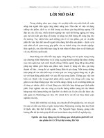
1-1-5
Wiring
z RS-485
• The RS-485 connection can be either one-to-one or one-to-N. Up to 32 units including the host
can be connected in a one-to-N system.
• The total cable length is 500 m max.
• Use a shielded twisted-pair cable with a wire gauge of AWG24 to AWG18 (cross-sectional area of
0.205 to 0.823 mm2).
E5CC/EC/AC
Communications
transceiver
Host
RS-485
E5CC/EC/AC
RS-485
Abbreviation
FG
TX
Abbreviation
−
Pin
14
+
13
B (+)
A (−)
RX
SG
6.8 V
A < B: "1" Mark
A > B: "0" Space
Shield
Terminator
120 Ω
(1/2 W)
E5CC/EC/AC
End node
RS-485
Pin
Specify both ends of the transmission path including the host
as the end node (that is, connect terminators to both ends).
Use a terminating resistance of at least 54 Ω.
1-4
Shield
Abbreviation
14
A (−)
13
B (+)
Use a 120 Ω (1/2 W)
terminator.
E5@C Digital Temperature Controllers Communications Manual (H175)
1 Communications Methods
1-1 Overview of Communications Methods
E5DC
Communications
transceiver
Host
RS-485
E5DC
RS-485
Abbreviation
FG
TX
Pin
4
Abbreviation
−
+
3
B (+)
1
A (−)
RX
1-1-5 Wiring
SG
6.8 V
Shield
A < B: "1" Mark
A > B: "0" Space
Terminator
120 Ω
(1/2 W)
Specify both ends of the transmission path including the host
as the end node (that is, connect terminators to both ends).
Use a terminating resistance of at least 54 Ω.
Shield
E5DC
End node
RS-485
Pin
Abbreviation
4
A (−)
3
B (+)
Use a 120 Ω (1/2 W) terminator.
E5GC
Communications transceiver
Host
RS-485
Abbreviation
E5GC
RS-485
FG
Pin
Abbreviation
−
8
A(-)
+
7
B(+)
TX
RX
SG
6.8V
A < B: "1" Mark
Shield
120 Ω (1/2 W) E5GC
terminating
End node
resistance
RS-485
A > B: “0” Space
Specify both ends of the transmission path
including the host as the end node (that is,
connect terminators to both ends). Use a
terminating resistance of at least 54 Ω.
Shield
Pin
Abbreviation
8
A(-)
7
B(+)
Use a 120 Ω (1/2 W) terminator.
Match the communications specifications of the E5@C and the host. When using a 1:N connection,
set the same communications specifications in all of the Units. Each Communications Unit must
have a unique unit number.
This section explains how to set the E5@C's communications specifications. For details on the host,
refer to the user's manual provided with the host.
E5@C Digital Temperature Controllers Communications Manual (H175)
1-5
1 Communications Methods
1-1-6
Communications Parameters
The E5@C's communications specifications are set in the communications setting level. These parameters are set on the E5@C's front panel. The following table shows the communications parameters and
their setting ranges.
Item
Communications protocol
setting
Communications unit number
Communications baud rate
Communications data length *
Communications stop bits *
Communications parity
Send data wait time
Code
psel
u-no
bps
len
sbit
prty
sdwt
Settings
CompoWay/F /Modbus
cwf/mod
Set Values
0 to 99
9.6/19.2/38. 4/57.6 (kbit/s)
7/8 (bit)
1/2
None, Even, Odd
0 to 99
0, 1 to 99
9.6/19.2 /38.4/57.6 (kbit/s)
7/8 (bit)
1/2
none/eVen/odd
0 to 99 ms, default time: 20 ms
Highlighted values indicate default settings.
*
1-6
When the Protocol Setting parameter is set to Modbus, the communications data length must be 8 bits, and the
communications stop bits must be 1 bit by setting the communications parity to Even/Odd or it must be 2 bits
by setting the parity to None. These two parameters are not displayed on the Controller's display.
E5@C Digital Temperature Controllers Communications Manual (H175)
1 Communications Methods
Before you carry out communications with the E5@C, set up the communications unit number, baud
rate, and other parameters by carrying out the following procedure. For details on operations other than
communications parameter setup, refer to the E5@C Digital Temperature Controllers User's Manual
(Cat. No. H174) for the devices being used.
1-1 Overview of Communications Methods
(1) Press the O Key for at least three seconds to move from the "operation level" to the
"initial setting level."
1
1-1-7
Communications Parameter Setup
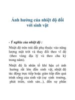
(3) Select the parameters as shown below by pressing the M Key.
(4) Use the D or U Keys to change the parameter set values.
psel
Protocol Setting
cwf
M
u-no
1
Communications Unit
No.
M
bps
9.6
Communications
Baud Rate
M
len
7
Communications Data
Length *
M
sbit
2
Communications Stop
Bits *
M
prty
Communications
even Parity
M
sdwt
Send Data Wait Time
20
M
*
Displayed only when the Protocol Setting parameter is set to CompoWay/F.
E5@C Digital Temperature Controllers Communications Manual (H175)
1-7
1-1-7 Communications Parameter Setup
(2) Press the O Key for less than one second to move from the "initial setting level" to
the "communications setting level."