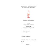
Lý thuyết hệ thống tuyến tính
Bạn đang xem bản rút gọn của tài liệu. Xem và tải ngay bản đầy đủ của tài liệu tại đây (3.7 MB, 94 trang )
Dynamic Systems and Control, Chapter 2: Linear System Theory
Linear System Theory
© 2016 Quoc Chi Nguyen, Head of Control & Automation Laboratory,
2-1
Dynamic Systems and Control, Chapter 2: Linear System Theory
Response Analysis of Systems
• In analyzing and designing control systems, we must have a
basis of comparison of performance of various control
systems.
• This basis may be set up by specifying particular test input
signals and by comparing the responses of various systems
to these input signals.
• Many design criteria are based on the response to such test
signals.
• The use of test signals enables one to compare the
performance of many systems on the same basis
© 2016 Quoc Chi Nguyen, Head of Control & Automation Laboratory,
2-2
Dynamic Systems and Control, Chapter 2: Linear System Theory
Typical Test Signals
• The commonly used test input signals are step functions, ramp
functions, impulse functions, sinusoidal functions, and white noise
• Which of these typical input signals to use for analyzing system
characteristics may be determined by the form of the input that the
system will be subjected to most frequently under normal
operation
© 2016 Quoc Chi Nguyen, Head of Control & Automation Laboratory,
2-3
Dynamic Systems and Control, Chapter 2: Linear System Theory
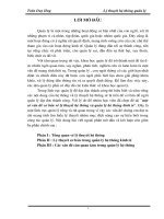
Transient Response and Steady-State Response
• The time response of a control system consists of two parts: the
transient response and the steady-state response
• By transient response, we mean that which goes from the
initial state to the final state
• By steady-state response, we mean the manner in which the
system output behaves as time approaches infinity
Step response
Harmonic response
© 2016 Quoc Chi Nguyen, Head of Control & Automation Laboratory,
2-4
Dynamic Systems and Control, Chapter 2: Linear System Theory
Step response
Example
Harmonic response
© 2016 Quoc Chi Nguyen, Head of Control & Automation Laboratory,
2-5
Dynamic Systems and Control, Chapter 2: Linear System Theory
Bounded Input Bounded Output Stability
• A system is BIBO (bounded-input bounded-output) stable if
every bounded input produces a bounded output
A SISO system is BIBO stable if and only if its impulse response
g(t) is absolutely integrable in the interval [0,∞), i.e.,
∞
� 𝑔𝑔(𝜏𝜏) 𝑑𝑑𝜏𝜏 ≤ 𝑀𝑀
0
for some finite constant M ≥ 0
© 2016 Quoc Chi Nguyen, Head of Control & Automation Laboratory,
2-6
Dynamic Systems and Control, Chapter 2: Linear System Theory
First-Order System
The input-output relationship is given by the differential equation
𝑑𝑑𝑑𝑑(𝑡𝑡) 1
+ 𝑐𝑐 𝑡𝑡 = 𝑟𝑟 𝑡𝑡
𝑑𝑑𝑑𝑑
𝑇𝑇
Ex: RC circuit and thermal system
The transfer function is
© 2016 Quoc Chi Nguyen, Head of Control & Automation Laboratory,
2-7
Dynamic Systems and Control, Chapter 2: Linear System Theory
Unit Impulse Response of First-Order Systems-Order System
The output of the system can be obtained as
Taking inverse Laplace transform gives
© 2016 Quoc Chi Nguyen, Head of Control & Automation Laboratory,
2-8
Dynamic Systems and Control, Chapter 2: Linear System Theory
Unit-Step Response of First-Order Systems
We obtain
Taking the inverse Laplace transform
© 2016 Quoc Chi Nguyen, Head of Control & Automation Laboratory,
2-9
Dynamic Systems and Control, Chapter 2: Linear System Theory
Unit-Step Response of First-Order Systems
Block diagram
Error signal
𝑒𝑒 𝑡𝑡 = 𝑟𝑟 𝑡𝑡 − 𝑐𝑐 𝑡𝑡 = 𝑒𝑒 −𝑡𝑡⁄𝑇𝑇
𝑡𝑡 → ∞, 𝑒𝑒(𝑡𝑡) → 0
© 2016 Quoc Chi Nguyen, Head of Control & Automation Laboratory,
2-10
Dynamic Systems and Control, Chapter 2: Linear System Theory
Unit-Ramp Response of First-Order Systems
We obtain
Taking the inverse Laplace transform
The error signal e(t) is then
e(∞)=T
© 2016 Quoc Chi Nguyen, Head of Control & Automation Laboratory,
2-11
Dynamic Systems and Control, Chapter 2: Linear System Theory
Unit-Ramp Response of First-Order Systems
© 2016 Quoc Chi Nguyen, Head of Control & Automation Laboratory,
2-12
Dynamic Systems and Control, Chapter 2: Linear System Theory
Second-Order System
We consider a servo system as an example of a second-order system.
The system consists of a proportional controller and load elements
(inertia and viscous-friction elements). Suppose that we wish to control
the output position c(t) in accordance with the input position r(t).
© 2016 Quoc Chi Nguyen, Head of Control & Automation Laboratory,
2-13
Dynamic Systems and Control, Chapter 2: Linear System Theory
Second-Order System
Dynamic equation of the servo system
Taking Laplace function yields
The closed-loop transfer function is then obtained as
The closed-loop transfer function possesses two poles is called a secondorder system
© 2016 Quoc Chi Nguyen, Head of Control & Automation Laboratory,
2-14
Dynamic Systems and Control, Chapter 2: Linear System Theory
Step Response of Second-Order Systems
𝜔𝜔𝑛𝑛 2 , undamped frequency
, attenuation
Damping ratio:
© 2016 Quoc Chi Nguyen, Head of Control & Automation Laboratory,
2-15
Dynamic Systems and Control, Chapter 2: Linear System Theory
© 2016 Quoc Chi Nguyen, Head of Control & Automation Laboratory,
2-16
Dynamic Systems and Control, Chapter 2: Linear System Theory
Step Response of Second-Order Systems: Undamped Case
2
2
ω
ω
ς
1
ω
1
ς
=
−
=
−
with d
n
n
Taking inverse Laplace transform
c(t)
© 2016 Quoc Chi Nguyen, Head of Control & Automation Laboratory,
2-17
Dynamic Systems and Control, Chapter 2: Linear System Theory
Step Response of Second-Order Systems: Overdamped Case
Taking inverse Laplace transform
© 2016 Quoc Chi Nguyen, Head of Control & Automation Laboratory,
2-18
Dynamic Systems and Control, Chapter 2: Linear System Theory
Step Response of Second-Order Systems: Critically Case
Taking inverse Laplace transform
Approximate form
© 2016 Quoc Chi Nguyen, Head of Control & Automation Laboratory,
2-19
Dynamic Systems and Control, Chapter 2: Linear System Theory
Definitions of Transient-Response Specifications
Delay time
Time required for the response to
reach half the final value the very first
time
Frequently, the performance characteristics of a control system are
specified in terms of the transient response to a unit-step input, since it is
easy to generate and is sufficiently drastic
© 2016 Quoc Chi Nguyen, Head of Control & Automation Laboratory,
2-20
Dynamic Systems and Control, Chapter 2: Linear System Theory
Definitions of Transient-Response Specifications
Rise time
The rise time is the time required for
the response to rise from
10%to 90%, 5% to 95%, or 0% to 100%
of its final value
Underdamped system
© 2016 Quoc Chi Nguyen, Head of Control & Automation Laboratory,
2-21
Dynamic Systems and Control, Chapter 2: Linear System Theory
Definitions of Transient-Response Specifications
Rise time
The rise time is the time required for
the response to rise from
10%to 90%, 5% to 95%, or 0% to 100%
of its final value
Overdamped system
© 2016 Quoc Chi Nguyen, Head of Control & Automation Laboratory,
2-22
Dynamic Systems and Control, Chapter 2: Linear System Theory
Definitions of Transient-Response Specifications
Peak time
The time required for the response to
reach the first peak of the overshoot
© 2016 Quoc Chi Nguyen, Head of Control & Automation Laboratory,
2-23
Dynamic Systems and Control, Chapter 2: Linear System Theory
Definitions of Transient-Response Specifications
Maximum overshoot
The maximum peak value of the
response curve measured from unity
© 2016 Quoc Chi Nguyen, Head of Control & Automation Laboratory,
2-24
Dynamic Systems and Control, Chapter 2: Linear System Theory
Definitions of Transient-Response Specifications
Settling time
Time required for the response curve
to reach and stay within a range about
the final value of size specified by
absolute percentage of the final value
(usually 2% or 5
© 2016 Quoc Chi Nguyen, Head of Control & Automation Laboratory,
2-25