Xe ô tô hyundai excel toàn tập hyundai excel - P2
Bạn đang xem bản rút gọn của tài liệu. Xem và tải ngay bản đầy đủ của tài liệu tại đây (2.39 MB, 77 trang )
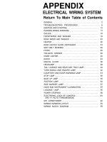
APPENDIX
ELECTRICAL WIRING SYSTEM
Return To Main Table of Contents
GENERAL
.......................................................
2
TROUBLESHOOTlNG PROCEDURES
............................
8
IGNITION AND STARTlNG ..................................... 12
PARKING BRAKE WARNING
..................................
14
GAUGE..
.....................................................
16
FRONTWlPER AND WASHER .................................
18
REAR WlPER AND WASHER
...................................
20
HEATER
.......................................................
22
REAR HEATED GLASS (DEFOGGER)
..........................
24
SEAT BELT WARNlNG
.........................................
26
HORN..
.........................................................
28
TAILGATE OPENER ...........................................
30
CIGAR LIGHTER
............................................... 32
AUDIO
........................................................
34
DIGITAL CLOCK ...............................................
36
HEADLAMP
...................................................
38
TAIL, LICENCE AND REAR ASH TRAY LAMP
..................
40
TURN SIGNAL AND HAZARD LAMP ...........................
42
COURTESY AND DOOR WARNING LAMP
..................... 44
STOP LAMP
..................................................
46
BACK UP LAMP
..................
..............................
48
POSITION LAMP
..............................................
50
SIDE MARKER LAMP
..........................................
52
DASH AND INSTRUMENT ILLUMINATION
.....................
54
LUGGAGE LAMP
............................................. 56
POWER STEERING
............................................ 58
ELECTRONIC LOCK-UP CONTROL
..............................
60
(KM 171 AUTO TRANSMISSION)
AIR CONDITIONER ............................................
62
WIRING HARNESS LAYOUT
................................... 64
WIRING BLOCK DIAGRAM
....................................
69
GENERAL
GENERAL
SYMBOLS IN CIRCUIT DIAGRAM
2
GENERAL
SIZE OF WIRE
Permissible current of each cable is determined by wire sectional
area which is given at the top of the wiring identification.
When an optional part is installed later, pay attention that the size
of wire must be determined with electrical load of the optional part
to prevent the excessive current.
Nominal
size
0.3 mm
2
AWG
22 -
5A 2.0
mm
2
0.5 mm
2
AWG
20 7A
13A 3.0
mm
2
0.85 mm
2
AWG
18
9A
17A 5.0
mm
2
1.25 mm
2
AWG 16
12A
22A
Permissible current
SAE gage No.
Nominal
In engine
Other area
size
compartment
ABBREVIATED SYMBOLS
SYMBOL
ACC
ALTR
ARM
ANT
A/T
A/CON
A/TRAY
BATT
CARB
COMB
CONN
DR
ENG
EXT
E.T.R.
FRT
F.B.C.
F.I.C.D.
MEANING
Accessory
Alternator
Armature
Antenna
Automatic transmission
Air conditioner
Ash tray
Battery (B+)
Carburetor
Combination (STOP, TAIL, BACK UP
AND T/SIG LAMP)
Connector
Door
Engine
Extension (wire off main harness)
Electronically tuning radio
Front
Feed back carburetor
Fast idle control device
SYMBOL
G/BOX
GND
H/LAMP
HTD
IGN
ILL
IND
INTERM
LH
MULTI SW
M/T
RR
RH
ST
SOL
S/BELT
SW
TEMP
T/SIG
Permissible current
SAE gage No.
In engine
Other area
compartment
MEANING
Glove box
Ground
Head lamp
Heated
Ignition
Illumination
Indicator
Intermittent
Left hand
Multifunction switch
Manual transmission
Rear (Left or Right rear)
Right hand
Start
Solenoid
Seat belt
Switch
Temperature
Turn signal
3
GENERAL
WIRE COLORS IN CIRCUIT DIAGRAM
Colored wire as shown in the following tables are used.
When two colors are used in a wire, the designation of the wire is
as follows.
SYMBOL COLOR OF WIRE
CIRCUIT
SYSTEM
B
Black
Grounding
BY
Black/Yellow
Start motor, tailgate opener switch
Starting and ground
BW
Black/White
Ignition coil
BR
Black/Red
Rear wiper and washer, illumination
Charging
W White
Alternator, fusible link
R
Red
Battery, multi switch, cluster
RW
Red/White
Headlamp
Lighting
RL
Red/Blue
Headlamp relay, Back up lamp
G
Green
Chime bell, license lamp, room lamp, stop lamp
GW
Green/White
GY
Green/Yellow
GB
Green/Black
Position lamp, rear ash tray, tail lamp, side maker
Signal
Turn signal lamp
Horn, parking brake
Y
Yellow
Heated timer
YBr
Yellow/Brown
Turn signal lamp, radio
YG
Yellow/Green
Temperature sensor
Instrument
YR
Yellow/Red
Fuel sender
L
Blue
Front wiper and washer
Heater, cigar lighter, luggage lamp
Other
Defogger switch, headlamp relay, clock
Lg
Light green
Multi switch, radio
GENERAL
CONNECTOR CLASSIFICATIONS
Electrical wiring connectors are classified according to the wiring parts.
THE PART NAME OF WIRING HARNESS
LOCATION
CONNECTOR IDENTIFI-
CATION SYMBOL
Main wiring harness
Engine compartment
Lock up wiring harness
Dash and steering column
M01 . . . . . . . . . . . . . . . M76
Crash pad wiring harness
Instrument wiring harness
Rear wiring harness
RH/LH rear extension wiring harness
Rear extension wiring harness
Tailgate wiring harness (except 4 door)
Air conditioner wiring harness
Dash. column
Front door speaker
The cluster and switch of
instrument
C01
. . . . . . . . . . . . . . . C23
I01 . . . . . . . . . . . . . . . . I09
Passenger compartment
R01
. . . . . . . . . . . . . . . R20
Tailgate
Engine compartment
Dash column
T01 . . . . . . . . . . . . . . . . .T08
A01 . . . . . . . . . . . . . . . A10
A connector identification symbol consists of a wiring harness location classification symbol corresponding to each
wiring harness location and number peculiar to the connector.
These connector locations can be found in the WIRING HARNESS LAYOUT.
M 10
Number peculiar to connector (Serial number)
Symbol indicating wiring harness (Main wiring harness)
NOTE
Connectors which connect each wiring harness are represented as following symbol.
For example;
M R 01
SPLICING SYMBOLS
Number peculiar to
connector (serial number)
Rear wiring harness
Main wiring harness
Splicing symbols are represented as following symbol.
For example;
S M 01
Number peculiar to splicing joint (serial number)
Main wiring
Splicing
5
GENERAL
CONNECTOR IDENTIFICATION SYMBOLS
Connectors and connector pin numbers are indicated in each cir-
cuit. Wires and pins of the connectors are also clearly illustrated.
6
GROUNDING POINTS
TROUBLESHOOTING PROCEDURES
TESTING FOR VOLTAGE
1. Connect one lead of a test light or voltmeter to a known good
ground. If you are using a voltmeter, be sure it is the voltmeter’s
negative lead that you have connected to ground.
2. Connect the other lead of the test light or voltmeter to a selected
test point (connector or terminal).
3.
If the test light glows, there is voltage present. If you are using a
voltmeter, note the voltage reading.
The allowable error should be within one volt of measured
battery voltage.
A loss of more than one volt indicates a problem.
TROUBLESHOOTING PROCEDURES
TESTING FOR CONTINUITY
1. Disconnect the battery.
2. Connect one lead of a self-powered test light or ohmmeter to
one end of the part of the circuit you wish to test.
3. Connect the other lead to the other end.
4. If the self-powered test light glows, there is continuity.
If you are using on ohmmeter, low or an resistance means good
continuity.
9
TROUBLESHOOTING PROCEDURES
TESTING FOR SHORT TO GROUND
1. Remove the blown fuse and disconnect the battery and load.
2. Connect one lead of a self-powered test light or ohmmeter to the
fuse terminal on the load side.
3. Connect the other lead to a known good ground.
4. Beginning near the fuse block, wiggle the harness from side to
side. Continue this at convenient point (about six inches apart)
while watching the self-powered test light or ohmmeter.
5.
When the self-powered test light glows, or ohmmeter registers,
there is a short to ground in the wiring near that point.
10
TROUBLESHOOTING PROCEDURES
TROUBLESHOOTING TOOLS
1. TEST LIGHT is made up of a 12-Volt light bulb with a pair of
leads attached. After grounding one lead, touch the other lead
to various points along the circuit where voltage should be
present. When the bulb goes on, there is voltage at the point
being tested.
2. SELF POWER TEST LIGHT
NOTE
A self-power test light is only used on an unpowered circuit.
Use a self-power test light to check for continuity.
This tool is made up of a light bulb, battery and two leads. If the
leads are touched together, the bulb will go on.
3.
JUMPER WIRE is made up of an in-line fuse holder connected to
a set of test lead.
Use it for by passing open circuits.
CAUTION
Never use a jumper wire between source and ground.
4. VOLTMETER can be used instead of a test light while a test light
shows whether or not voltage is present, a voltmeter indicates
how much voltage is present.
5. OHMMETER can be used instead of a self-power test light. The
ohmmeter shows how much resistance there is between two
points along a circuit. Low resistance means good continuity.
6. DIGITAL MULTIMETER can be used instead of a ohmmeter,
voltmeter and ammeter.
11
IGNITION AND STARTING
SCHEMATIC DIAGRAM
12
IGNITION AND STARTING
CONFIGURATION OF CONNECTORS
13
PARKING BRAKE WARNING
SCHEMATIC DIAGRAM
14
PARKING BRAKE WARNING
CONFIGURATION OF CONNECTORS
GAUGE
SCHEMATIC DIAGRAM
16
GAUGE
CONFIGURATION OF CONNECTORS
FRONT WIPER AND WASHER
SCHEMATIC DIAGRAM
18
FRONT WIPER AND WASHER
CONFIGURATION OF CONNECTORS
19
REAR WIPER AND WASHER
SCHEMATIC DIAGRAM
20
REAR WIPER AND WASHER
CONFIGURATION OF CONNECTORS
21
HEATER
SCHEMATIC DIAGRAM
22
HEATER
CONFIGURATION OF CONNECTORS
23
REAR HEATED GLASS (DEFOGGER)
SCHEMATIC DIAGRAM
24
REAR HEATED GLASS (DEFOGGER)
CONFIGURATION OF CONNECTORS
25