Xe ô tô hyundai excel toàn tập hyundai excel - P5
Bạn đang xem bản rút gọn của tài liệu. Xem và tải ngay bản đầy đủ của tài liệu tại đây (993.65 KB, 41 trang )
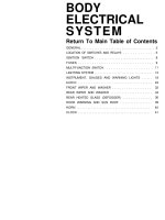
BODY
ELECTRICAL
SYSTEM
Return To Main Table of Contents
GENERAL ........................................
2
LOCATION OF SWlTCHES AND RELAYS
.............
5
IGNITION SWITCH ................................ 8
FUSES ..................................... 9
MULTIFUNCTION SWITCH....................
11
LIGHTING SYSTEM ................................. 13
INSTRUMENT, GAUGES AND WARNING LIGHTS ...... 18
AUDIO ....................................... 24
FRONT WIPER AND WASHER ................... 32
REAR WIPER AND WASHER ...................... 34
REAR HEATED GLASS (DEFOGGER) ...............
36
DOOR WARNING AND SUN ROOF ..................
39
HORN ........................................ 40
CLOCK .........................................
41
GENERAL
GENERAL
SERVICING THE ELECTRICAL SYSTEM
When servicing the electrical system, disconnect the negative
cable from the terminal of the battery.
CAUTION
Before connecting or disconnecting the negative cable, be
sure to turn off the ignition switch and the lighting switch.
(If this is not done, there is the possibility of the semiconduc-
tor parts being damaged.)
Secure the wiring harnesses by using clamps so that there is no
slack. However, for any harness which passes to the engine or
other vibrating parts of the vehicle, allow some slack within a
range that does not allow the engine vibrations to cause the
harness to come into contact with any of the surrounding parts,
and then secure the harness by using a clamp.
If any section of a wiring harness interferes with the edge of a
part, or a corner, wrap the section of the harness with tape or
something similar in order to protect it from damage.
When installing any of the vehicle parts, be careful not to pinch
or damage any of the wiring harnesses.
90-2
GENERAL
If a burned-out fuse is to be replaced, be sure to use only a fuse
of the specified capacity. If a fuse a capacity larger than that
specified is used, parts may be damaged and the danger of fire
also exists.
10A
15A
The sensors, relays, etc., must never be subjected to strong
shocks. Do not allow them to fall and do not throw them when
handling.
The electronic parts used in the computer, relays, etc. are read-
ily damaged by heat. If there is a need for service operations that
may cause the temperature to exceed 80°C (176°F), remove the
electronic parts beforehand.
Loose connectors could troubles. Make sure that the connec-
tors are connected securely.
GENERAL
When disconnecting a connector, be sure to pull only the con-
nector, not the harness.
Disconnect connectors which have catches by pressing in the
direction indicated by the arrows in the illustration.
Connect connectors which have catches by inserting the con-
nectors until a “snap” noise is heard.
When using a circuit tester to perform continuity or voltage
checks on connector terminals, insert the test probe from the
harness side.
If the connector is a sealed connector, insert the test probe in
through the hole in the rubber cap for the electrical wires, being
careful not to damage the insulation of the wires; continue to
insert the test probe until it contacts the terminal.
90-4
LOCATION OF SWITCHES AND RELAYS
LOCATION OF SWITCHES AND RELAYS
ENGINE COMPARTMENT SWITCHES AND RELAY (3, 4, 5 DOOR)
90-5
LOCATION OF SWITCHES AND RELAYS
DASH AND STEERING COLUMN SWITCHES AND RELAYS (3, 4, 5 DOOR)
MULTIFUNCTION SWITCH
90-6
LOCATION OF SWITCHES AND RELAYS
PASSENGER AND LUGGAGE COMPARTMENT SWITCHES AND RELAYS
90-7
IGNITION SWITCH
IGNITION SWITCH
INSPECTION
1.
Inspect the switch continuity between terminals. If continuity is
not as specified, replace the switch.
90-8
FUSES
FUSES
FUSIBLE LINKS
Inspection
1. Check for a burnt fusible link with a ohmmeter.
2. If a fusible link burns out, there is a short or some other problem
in the circuit. Carefully determine the cause and correct it
before replacing the fusible link.
NOTE
The fusible link will burnt out within 15 seconds if a higher
than specified current flows through the circuit.
IGNITION
HEAD LAMP
BATTERY ALTERNATOR
Fusible link
color
Permissible
continuous
current A.
Pink
Pink
Pink
Yellow
30
30 30 60
Fusing
current A.
90
90 90 180
FUSE BOX
Inspection
1.
Be sure there is no play in the fuse holders, and that the holders
hold the fuses securely.
2. Are fuse capacities for each circuit correct ?
3. Are there any blown fuse ?
If a fuse is to be replaced, be sure to use a new fuse of the
specified capacity. Always determine why the fuse blew first.
CAUTION
Newer use a fuse of higher capacity than specified.
10A
15A
FUSES
When replacing a fuse, use the puller in the fuse box.
SCHEMATIC DIAGRAM
PASSIVE SEAT BELT TYPE
90-10
MULTIFUNCTION SWITCH
MULTIFUNCTION SWITCH
INSPECTION
1.
Check for continuity between the terminals in each switch posi-
tion according to the table.
CAUTION
(a) Make sure the wire leads are not being pulled when you
move the lever.
(b) Check that the lever works freely without binding.
NO
CIRCUIT WIRE SIDE
DESCRIPTION
1
ES
0.3 B
HEAD LAMP SW GROUND.
2
HS (1)
0.3 Lg
HEAD LAMP SW.
3 HU
2.0 RL H/LAMP UPPER BEAM POWER.
4 HL
1.25 RY
5
W
0.5 BW
6 HI
0.85 LW
7 LO
0.85 LR
8 INT
0.85 G
9
TR
0.85 GY
10
BB
0.85 GW
11 Eb
2.0 B
12
PL
13
B+
14
C
15 HO
16 TS
17
HS (2)
18
P
19 Ew
20 TL
21 IG
0.5 L
0.85 RG
0.85 Br
0.5 RB
0.3 R
0.5 Lg
0.85 GB
0.85 B
0.85 YBr
0.85 RL
H/LAMP LOWER BEAM POWER.
WASHER.
WIPER HIGH SPEED,
WIPER LOW SPEED.
INTERMllTENT WIPER.
T/SIG RH LAMP.
FLASH UNIT POWER.
H/LAMP BEAM SW GROUND
PILOT LAMP (HAZARD).
BATTERY POWER.
COMMON.
HORN.
TAIL LAMP SW.
H/LAMP SW PASSING.
WIPER PARKING.
WIPER WASHER SW GROUND.
T/ SIG LH LAMP.
IGNITION POWER.
REMOVAL
1. Remove the steering wheel.
2. Remove the steering column shroud.
3. Remove the multifunction switch mounting screws.
4. Disconnect the multifunction switch wiring terminal.
MULTIFUNCTlON SWITCH
LIGHTING SWITCH
DIMMER/PASSING SWITCH
TURN SIGNAL/HAZARD SWITCH
WIPER SWITCH
WASHER SWITCH
90-12
LIGHTING SYSTEM
LIGHTING SYSTEM
Troubleshooting for the Lighting System
Problem
Only one lamp does
not light (all exterior)
No headlamps light
Tail, parking and
licence lamp do not
light
Stop lamps do not
light
Stop lamps stay on
Instrument lamps do not
light (taillamps light)
Turn signal does not
flash on one side
Turn signal do
not operate
Hazard warning lamps
do not operate
Possible cause
Light bulb burned out
Socket, wire or ground faulty
Fusible link blown
Headlamp relay faulty
Light control switch faulty
Wiring or ground faulty
TAIL fuse blown
Fusible link blown
Taillamp control relay faulty
Light control switch faulty
Wiring or ground faulty
STOP fuse blown
Stop lamp switch faulty
Wiring or ground faulty
Stop lamp switch faulty
Light control rheostat faulty
Wiring or ground faulty
Turn signal switch faulty
Wiring or ground faulty
TURN fuse blown
Turn signal flasher faulty
Turn signal/hazard switch faulty
Wiring or ground faulty
HAZARD fuse blown
Turn signal flasher faulty
Turn signal/hazard switch faulty
Wiring or ground faulty
HEAD LAMPS
Removal and Installation
1. Open the hood and disconnect the battery negative cable.
2. Remove the radiator grille.
3. Remove the front position lamp.
4. Remove the headlamp mounting bolts. Disconnect the wiring
connector.
5. Remove the headlamp assembly.
6. Installation is reverse order of the removal.
Remedy
Replace bulb
Repair as necessary
Replace fusible link
Check relay
Check switch
Repair as necessary
Replace fuse and check for short
Replace fusible link
Check relay
Check switch
Repair as necessary
Replace fuse and check for short
Adjust or replace switch
Repair as necessary
Adjust or replace switch
Check rheostat
Repair as necessary
Check switch
Repair as necessary
Replace fuse and check for short
Check flasher
Check switch
Repair as necessary
Replace fuse and check for short
Check flasher
Check switch
Repair as necessary
90-13
LIGHTING SYSTEM
HEADLAMP RELAY
inspection
1. Check for continuity between the terminals.
There should be continuity between L and B terminals when
the battery positive cable is connected to S2 terminal and
negative cable to S
1
terminal.
There should be no continuity between L and B terminals
when the battery is disconnected.
RHEOSTAT
Inspection
1. Check for the intensity. If the light intensity of the lamps
changes smoothly without any flickering when the rheostat is
turned, it can be assumed that the rheostat is functioning
properly.
HEADLIGHTS
Aiming
PRE-AIMING INSTRUCTIONS
1. Test dimmer switch operation.
2. Observe operation of high beam indicator light mounted in
instrument cluster.
3. Inspect for badly rusted or faulty headlight assemblies. These
conditions must be corrected before a satisfactory adjustment
can be made.
4. Place vehicle on a level floor.
5.
Bounce front suspension through three (3) oscillations by app-
lying body weight to hood or bumper.
6. Inspect tire inflation.
7. Rock vehicle sideways to allow vehicle to assume its normal
position.
8.
In gasoline tank is not full, place a weight in trunk of vehicle to
simulate weight of a full tank.
9. There should be no other load in the vehicle other than driver or
substituted weight of approximately 70 kg (150 lb.) placed in
driver’s position.
10. Throughly clean headlight lenses.
90-14
LIGHTING SYSTEM
COMPENSATING THE AIMERS FOR FLOOR SLOPE
The floor level offset dial must coincide with the floor slope for
accurate aiming. Calibration fixtures are included with the
aimers.
1. Attach one calibration fixture to each aimer. Fixtures will easily
snap into position on aimer when properly positioned.
2. Place aimers at center line of each wheel on one side of vehicle.
Unit A must be placed at rear wheel with target facing forward.
Unit B must be placed at front wheel target facing rearward.
3. Adjust thumb adjusting screw on each calibration fixture by
turning either clockwise or counter-clockwise until level vial
bubble registers in a centered, level position.
4. Look into top port hole of Unit A. Turn horizontal knob until split
image is aligned.
5. Transfer plus or minus reading indicated on horizontal dial to
floor level offset dial on each aimer. Press floor level dial inward
to set reading.
6. Remove calibration fixtures from both units.
TESTING AIMER CALIBRATION
The aimer calibration may be off due to extended use. Calibra-
tion fixtures used in conjuction with aimers can be used to
check and adjust aimers.
1.
Turn thumb adjusting screw on each calibration fixture until it is
approximately the same distance as the supporting posts.
2. Attach calibration fixtures to each unit with level vials on top.
3. Locate true vertical plate glass window or smooth surface and
secure aimers three to five feet apart so split image targets can
be located in viewing ports.
4. Set floor level dial at zero.
5. Rotate thumb adjusting screws on each calibration fixture until
level vials on fixtures are centered.
6. With both calibration level vials centered turn vertical dial knobs
on each aimer until aimer level vials are centered. If aimer
vertical dial pointers read between ½ up and ½ down, aimers
are within allowable vertical tolerance, Recalibrate units if
beyond these limits.
Vertical dial pointer reading (on each aimer) . . . . . . . . . . . .
½ up to ½ down
90-15
LIGHTING SYSTEM
7. Adjust horizontal dial knob on each aimer until split image
targets align. If aimer horizontal dial pointers read between 1
left and 1 right, the aimers are within allowable tolerance limits.
Recalibrate units if beyond these limits.
Horizontal dial pointer reading (on each aimer) . . . . . . . . . . . .
1 left to 1 right
MOUNTING AIMERS
1. Snap proper adaptor into position on each aimer making full
contact with aimer mounting flange.
2. Position aimers on headlights by pushing piston handle for-
ward, engaging rubber suction cup. Immediately pull back pis-
ton handle until it locks in place.
NOTE
Steel inserts are molded into position on the adaptor to insure
accuracy. These inserts must be in contact with the three
guide points on the lights when the aimers are properly
positioned.
HORIZONTAL ADJUSTMENT
1. Set horizontal dial to zero.
2. Check to see that the split image target lines are visible in the
viewing port. If necessary, rotate each aimer slightly to locate
the target.
3. Turn horizontal screw on side of headlight until split image of
target line appears in mirrors as one solid line. To remove
“backlash”, make final adjustment by turning adjusting screw
in a clockwise direction.
4. Repeat the last three steps on opposite headlight.
VERTICAL ADJUSTMENT
1. The vertical dial should be set at zero, (For passenger vehicles,
“0” setting is generally required. For special settings, consult
local state laws.)
2. Turn vertical adjusting screw until the level bubble is centered
between the lines.
3. Repeat the last two steps on the opposite headlight.
4. Re-check target alignment on both aimers and readjust horizon-
tal aim if necessary.
5. Remove aimers by pressing “vacuum release” button located on
piston handle.
90-16


