6 4 3 5 lab building a switch and router network kho tài liệu bách khoa
Bạn đang xem bản rút gọn của tài liệu. Xem và tải ngay bản đầy đủ của tài liệu tại đây (248.1 KB, 11 trang )
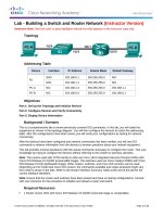
Lab - Building a Switch and Router Network
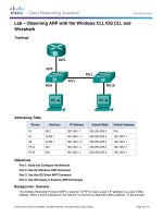
Topology
Addressing Table
Device
R1
Interface
IP Address
Subnet Mask
Default Gateway
G0/0
192.168.0.1
255.255.255.0
N/A
G0/1
192.168.1.1
255.255.255.0
N/A
S1
VLAN 1
N/A
N/A
N/A
PC-A
NIC
192.168.1.3
255.255.255.0
192.168.1.1
PC-B
NIC
192.168.0.3
255.255.255.0
192.168.0.1
Objectives
Part 1: Set Up the Topology and Initialize Devices
Set up equipment to match the network topology.
Initialize and restart the router and switch.
Part 2: Configure Devices and Verify Connectivity
Assign static IP information to the PC interfaces.
Configure the router.
Verify network connectivity.
Part 3: Display Device Information
Retrieve hardware and software information from the network devices.
Interpret the output from the routing table.
Display interface information on the router.
Display a summary list of the interfaces on the router and switch.
Background / Scenario
This is a comprehensive lab to review previously covered IOS commands. In this lab, you will cable the
equipment as shown in the topology diagram. You will then configure the devices to match the addressing
table. After the configurations have been saved, you will verify your configurations by testing for network
connectivity.
After the devices have been configured and network connectivity has been verified, you will use IOS
commands to retrieve information from the devices to answer questions about your network equipment.
© 2013 Cisco and/or its affiliates. All rights reserved. This document is Cisco Public.
Page 1 of 11
Lab - Building a Switch and Router Network
This lab provides minimal assistance with the actual commands necessary to configure the router. However,
the required commands are provided in Appendix A. Test your knowledge by trying to configure the devices
without referring to the appendix.
Note: The routers used with CCNA hands-on labs are Cisco 1941 Integrated Services Routers (ISRs) with
Cisco IOS Release 15.2(4)M3 (universalk9 image). The switches used are Cisco Catalyst 2960s with Cisco
IOS Release 15.0(2) (lanbasek9 image). Other routers, switches, and Cisco IOS versions can be used.
Depending on the model and Cisco IOS version, the commands available and output produced might vary
from what is shown in the labs. Refer to the Router Interface Summary Table at the end of this lab for the
correct interface identifiers.
Note: Ensure that the routers and switches have been erased and have no startup configurations. Refer to
Appendix B for the procedure to initialize and reload a router and switch.
Required Resources
1 Router (Cisco 1941 with Cisco IOS Release 15.2(4)M3 universal image or comparable)
1 Switch (Cisco 2960 with Cisco IOS Release 15.0(2) lanbasek9 image or comparable)
2 PCs (Windows 7, Vista, or XP with terminal emulation program, such as Tera Term)
Console cables to configure the Cisco IOS devices via the console ports
Ethernet cables as shown in the topology
Note: The Gigabit Ethernet interfaces on Cisco 1941 routers are autosensing and an Ethernet straightthrough cable may be used between the router and PC-B. If using another model Cisco router, it may be
necessary to use an Ethernet crossover cable.
Part 1: Set Up Topology and Initialize Devices
Step 1: Cable the network as shown in the topology.
a. Attach the devices shown in the topology diagram, and cable, as necessary.
b. Power on all the devices in the topology.
Step 2: Initialize and reload the router and switch.
If configuration files were previously saved on the router and switch, initialize and reload these devices back
to their basic configurations. For information on how to initialize and reload these devices, refer to Appendix
B.
Part 2: Configure Devices and Verify Connectivity
In Part 2, you will set up the network topology and configure basic settings, such as the interface IP
addresses, device access, and passwords. Refer to the Topology and Addressing Table at the beginning of
this lab for device names and address information.
Note: Appendix A provides configuration details for the steps in Part 2. You should attempt to complete Part 2
prior to reviewing this appendix.
Step 1: Assign static IP information to the PC interfaces.
a. Configure the IP address, subnet mask, and default gateway settings on PC-A.
b. Configure the IP address, subnet mask, and default gateway settings on PC-B.
© 2013 Cisco and/or its affiliates. All rights reserved. This document is Cisco Public.
Page 2 of 11
Lab - Building a Switch and Router Network
c.
Ping PC-B from a command prompt window on PC-A.
Why were the pings not successful?
Step 2: Configure the router.
a. Console into the router and enable privileged EXEC mode.
b. Enter configuration mode.
c.
Assign a device name to the router.
d. Disable DNS lookup to prevent the router from attempting to translate incorrectly entered commands as
though they were host names.
e. Assign class as the privileged EXEC encrypted password.
f.
Assign cisco as the console password and enable login.
g. Assign cisco as the VTY password and enable login.
h. Encrypt the clear text passwords.
i.
Create a banner that warns anyone accessing the device that unauthorized access is prohibited.
j.
Configure and activate both interfaces on the router.
k.
Configure an interface description for each interface indicating which device is connected to it.
l.
Save the running configuration to the startup configuration file.
m. Set the clock on the router.
Note: Use the question mark (?) to help with the correct sequence of parameters needed to execute this
command.
n. Ping PC-B from a command prompt window on PC-A.
Were the pings successful? Why?
Part 3: Display Device Information
In Part 3, you will use show commands to retrieve information from the router and switch.
Step 1: Retrieve hardware and software information from the network devices.
a. Use the show version command to answer the following questions about the router.
What is the name of the IOS image that the router is running?
How much DRAM memory does the router have?
How much NVRAM memory does the router have?
© 2013 Cisco and/or its affiliates. All rights reserved. This document is Cisco Public.
Page 3 of 11
Lab - Building a Switch and Router Network
How much Flash memory does the router have?
b. Use the show version command to answer the following questions about the switch.
What is the name of the IOS image that the switch is running?
How much dynamic random access memory (DRAM) does the switch have?
How much nonvolatile random-access memory (NVRAM) does the switch have?
What is the model number of the switch?
Step 2: Display the routing table on the router.
Use the show ip route command on the router to answer the following questions.
What code is used in the routing table to indicate a directly connected network?
How many route entries are coded with a C code in the routing table?
What interface types are associated to the C coded routes?
Step 3: Display interface information on the router.
Use the show interface g0/1 to answer the following questions.
What is the operational status of the G0/1 interface?
What is the Media Access Control (MAC) address of the G0/1 interface?
How is the Internet address displayed in this command?
Step 4: Display a summary list of the interfaces on the router and switch.
There are several commands that can be used to verify an interface configuration. One of the most useful of
these is the show ip interface brief command. The command output displays a summary list of the
interfaces on the device and provides immediate feedback to the status of each interface.
a. Enter the show ip interface brief command on the router.
R1# show ip interface brief
Interface
Embedded-Service-Engine0/0
GigabitEthernet0/0
GigabitEthernet0/1
Serial0/0/0
Serial0/0/1
R1#
IP-Address
unassigned
192.168.0.1
192.168.1.1
unassigned
unassigned
OK?
YES
YES
YES
YES
YES
Method
unset
manual
manual
unset
unset
© 2013 Cisco and/or its affiliates. All rights reserved. This document is Cisco Public.
Status
Protocol
administratively down down
up
up
up
up
administratively down down
administratively down down
Page 4 of 11
Lab - Building a Switch and Router Network
b. Enter the show ip interface brief command on the switch.
Switch# show ip interface brief
Interface
Vlan1
FastEthernet0/1
FastEthernet0/2
FastEthernet0/3
FastEthernet0/4
FastEthernet0/5
FastEthernet0/6
FastEthernet0/7
FastEthernet0/8
FastEthernet0/9
FastEthernet0/10
FastEthernet0/11
FastEthernet0/12
FastEthernet0/13
FastEthernet0/14
FastEthernet0/15
FastEthernet0/16
FastEthernet0/17
FastEthernet0/18
FastEthernet0/19
FastEthernet0/20
FastEthernet0/21
FastEthernet0/22
FastEthernet0/23
FastEthernet0/24
GigabitEthernet0/1
GigabitEthernet0/2
Switch#
IP-Address
unassigned
unassigned
unassigned
unassigned
unassigned
unassigned
unassigned
unassigned
unassigned
unassigned
unassigned
unassigned
unassigned
unassigned
unassigned
unassigned
unassigned
unassigned
unassigned
unassigned
unassigned
unassigned
unassigned
unassigned
unassigned
unassigned
unassigned
OK?
YES
YES
YES
YES
YES
YES
YES
YES
YES
YES
YES
YES
YES
YES
YES
YES
YES
YES
YES
YES
YES
YES
YES
YES
YES
YES
YES
Method
manual
unset
unset
unset
unset
unset
unset
unset
unset
unset
unset
unset
unset
unset
unset
unset
unset
unset
unset
unset
unset
unset
unset
unset
unset
unset
unset
Status
up
down
down
down
down
up
up
down
down
down
down
down
down
down
down
down
down
down
down
down
down
down
down
down
down
down
down
Protocol
up
down
down
down
down
up
up
down
down
down
down
down
down
down
down
down
down
down
down
down
down
down
down
down
down
down
down
Reflection
1. If the G0/1 interface showed administratively down, what interface configuration command would you use to
turn the interface up?
2. What would happen if you had incorrectly configured interface G0/1 on the router with an IP address of
192.168.1.2?
© 2013 Cisco and/or its affiliates. All rights reserved. This document is Cisco Public.
Page 5 of 11
Lab - Building a Switch and Router Network
Router Interface Summary Table
Router Interface Summary
Router Model
Ethernet Interface #1
Ethernet Interface #2
Serial Interface #1
Serial Interface #2
1800
Fast Ethernet 0/0
(F0/0)
Fast Ethernet 0/1
(F0/1)
Serial 0/0/0 (S0/0/0)
Serial 0/0/1 (S0/0/1)
1900
Gigabit Ethernet 0/0
(G0/0)
Gigabit Ethernet 0/1
(G0/1)
Serial 0/0/0 (S0/0/0)
Serial 0/0/1 (S0/0/1)
2801
Fast Ethernet 0/0
(F0/0)
Fast Ethernet 0/1
(F0/1)
Serial 0/1/0 (S0/1/0)
Serial 0/1/1 (S0/1/1)
2811
Fast Ethernet 0/0
(F0/0)
Fast Ethernet 0/1
(F0/1)
Serial 0/0/0 (S0/0/0)
Serial 0/0/1 (S0/0/1)
2900
Gigabit Ethernet 0/0
(G0/0)
Gigabit Ethernet 0/1
(G0/1)
Serial 0/0/0 (S0/0/0)
Serial 0/0/1 (S0/0/1)
Note: To find out how the router is configured, look at the interfaces to identify the router type and how many
interfaces the router has. There is no way to effectively list all the combinations of configurations for each router
class. This table includes identifiers for the possible combinations of Ethernet and Serial interfaces in the device.
The table does not include any other type of interface, even though a specific router may contain one. An
example of this might be an ISDN BRI interface. The string in parenthesis is the legal abbreviation that can be
used in Cisco IOS commands to represent the interface.
Appendix A: Configuration Details for Steps in Part 2
Step 1: Configure the PC interfaces.
a. Configure the IP address, subnet mask, and default gateway settings on PC-A.
b. Configure the IP address, subnet mask, and default gateway settings on PC-B.
© 2013 Cisco and/or its affiliates. All rights reserved. This document is Cisco Public.
Page 6 of 11
Lab - Building a Switch and Router Network
c.
Ping PC-B from a command prompt window on PC-A.
Step 2: Configure the router.
a. Console into the router and enable privileged EXEC mode.
Router> enable
Router#
b. Enter configuration mode.
Router# conf t
Enter configuration commands, one per line.
End with CNTL/Z.
Router(config)#
c.
Assign a device name to the router.
Router(config)# hostname R1
d. Disable DNS lookup to prevent the router from attempting to translate incorrectly entered commands as
though they were host names.
R1(config)# no ip domain-lookup
e. Assign class as the privileged EXEC encrypted password.
R1(config)# enable secret class
f.
Assign cisco as the console password and enable login.
R1(config)# line con 0
R1(config-line)# password cisco
R1(config-line)# login
© 2013 Cisco and/or its affiliates. All rights reserved. This document is Cisco Public.
Page 7 of 11
Lab - Building a Switch and Router Network
R1(config-line)# exit
R1(config)#
g. Assign cisco as the vty password and enable login.
R1(config)# line
R1(config-line)#
R1(config-line)#
R1(config-line)#
R1(config)#
vty 0 4
password cisco
login
exit
h. Encrypt the clear text passwords.
R1(config)# service password-encryption
i.
Create a banner that warns anyone accessing the device that unauthorized access is prohibited.
R1(config)# banner motd #
Enter TEXT message. End with the character '#'.
Unauthorized access prohibited!
#
R1(config)#
j.
Configure and activate both interfaces on the router.
R1(config)# int g0/0
R1(config-if)# description Connection to PC-B.
R1(config-if)# ip address 192.168.0.1 255.255.255.0
R1(config-if)# no shut
R1(config-if)#
*Nov 29 23:49:44.195: %LINK-3-UPDOWN: Interface GigabitEthernet0/0, changed state to
down
*Nov 29 23:49:47.863: %LINK-3-UPDOWN: Interface GigabitEthernet0/0, changed state to
up
*Nov 29 23:49:48.863: %LINEPROTO-5-UPDOWN: Line protocol on Interface
GigabitEthernet0/0, changed state to up
R1(config-if)# int g0/1
R1(config-if)# description Connection to S1.
R1(config-if)# ip address 192.168.1.1 255.255.255.0
R1(config-if)# no shut
R1(config-if)# exit
R1(config)# exit
*Nov 29 23:50:15.283: %LINK-3-UPDOWN: Interface GigabitEthernet0/1, changed state to
down
*Nov 29 23:50:18.863: %LINK-3-UPDOWN: Interface GigabitEthernet0/1, changed state to
up
*Nov 29 23:50:19.863: %LINEPROTO-5-UPDOWN: Line protocol on Interface
GigabitEthernet0/1, changed state to up
R1#
k.
Save the running configuration to the startup file.
R1# copy running-config startup-config
Destination filename [startup-config]?
Building configuration...
© 2013 Cisco and/or its affiliates. All rights reserved. This document is Cisco Public.
Page 8 of 11
Lab - Building a Switch and Router Network
[OK]
R1#
l.
Set the clock on the router.
R1# clock set 17:00:00 29 Nov 2012
R1#
*Nov 29 17:00:00.000: %SYS-6-CLOCKUPDATE: System clock has been updated from 23:55:46
UTC Thu Nov 29 2012 to 17:00:00 UTC Thu Nov 29 2012, configured from console by
console.
R1#
Note: Use the question mark (?) to help determine the correct sequence of the parameters needed to
execute this command.
m. Ping PC-B from a command prompt window on PC-A.
Appendix B: Initializing and Reloading a Router and Switch
Part 1: Initialize the Router and Reload
Step 1: Connect to the router.
Console into the router and enter privileged EXEC mode using the enable command.
Router> enable
Router#
Step 2: Erase the startup configuration file from NVRAM.
Type the erase startup-config command to remove the startup configuration from nonvolatile randomaccess memory (NVRAM).
Router# erase startup-config
Erasing the nvram filesystem will remove all configuration files! Continue? [confirm]
[OK]
Erase of nvram: complete
Router#
Step 3: Reload the router.
Issue the reload command to remove an old configuration from memory. When prompted to Proceed with
reload, press Enter to confirm the reload. Pressing any other key will abort the reload.
Router# reload
© 2013 Cisco and/or its affiliates. All rights reserved. This document is Cisco Public.
Page 9 of 11
Lab - Building a Switch and Router Network
Proceed with reload? [confirm]
*Nov 29 18:28:09.923: %SYS-5-RELOAD: Reload requested by console. Reload Reason:
Reload Command.
Note: You may receive a prompt to save the running configuration prior to reloading the router. Respond
by typing no and press Enter.
System configuration has been modified. Save? [yes/no]: no
Step 4: Bypass the initial configuration dialog.
After the router reloads, you are prompted to enter the initial configuration dialog. Enter no and press Enter.
Would you like to enter the initial configuration dialog? [yes/no]: no
Step 5: Terminate the autoinstall program.
You will be prompted to terminate the autoinstall program. Respond yes and then press Enter.
Would you like to terminate autoinstall? [yes]: yes
Router>
Part 2: Initialize the Switch and Reload
Step 1: Connect to the switch.
Console into the switch and enter privileged EXEC mode.
Switch> enable
Switch#
Step 2: Determine if there have been any virtual local-area networks (VLANs) created.
Use the show flash command to determine if any VLANs have been created on the switch.
Switch# show flash
Directory of flash:/
2
3
4
5
6
-rwx
-rwx
-rwx
-rwx
-rwx
1919
1632
13336
11607161
616
Mar
Mar
Mar
Mar
Mar
1
1
1
1
1
1993
1993
1993
1993
1993
00:06:33
00:06:33
00:06:33
02:37:06
00:07:13
+00:00
+00:00
+00:00
+00:00
+00:00
private-config.text
config.text
multiple-fs
c2960-lanbasek9-mz.150-2.SE.bin
vlan.dat
32514048 bytes total (20886528 bytes free)
Switch#
Step 3: Delete the VLAN file.
a. If the vlan.dat file was found in flash, then delete this file.
Switch# delete vlan.dat
Delete filename [vlan.dat]?
You will be prompted to verify the file name. At this point, you can change the file name or just press
Enter if you have entered the name correctly.
© 2013 Cisco and/or its affiliates. All rights reserved. This document is Cisco Public.
Page 10 of 11
Lab - Building a Switch and Router Network
b. When you are prompted to delete this file, press Enter to confirm the deletion. (Pressing any other key will
abort the deletion.)
Delete flash:/vlan.dat? [confirm]
Switch#
Step 4: Erase the startup configuration file.
Use the erase startup-config command to erase the startup configuration file from NVRAM. When you are
prompted to remove the configuration file, press Enter to confirm the erase. (Pressing any other key will abort
the operation.)
Switch# erase startup-config
Erasing the nvram filesystem will remove all configuration files! Continue? [confirm]
[OK]
Erase of nvram: complete
Switch#
Step 5: Reload the switch.
Reload the switch to remove any old configuration information from memory. When you are prompted to
reload the switch, press Enter to proceed with the reload. (Pressing any other key will abort the reload.)
Switch# reload
Proceed with reload? [confirm]
Note: You may receive a prompt to save the running configuration prior to reloading the switch. Type no
and press Enter.
System configuration has been modified. Save? [yes/no]: no
Step 6: Bypass the initial configuration dialog.
After the switch reloads, you should see a prompt to enter the initial configuration dialog. Type no at the
prompt and press Enter.
Would you like to enter the initial configuration dialog? [yes/no]: no
Switch>
© 2013 Cisco and/or its affiliates. All rights reserved. This document is Cisco Public.
Page 11 of 11