6 2 3 8 lab configuring multiarea OSPFv2 kho tài liệu bách khoa
Bạn đang xem bản rút gọn của tài liệu. Xem và tải ngay bản đầy đủ của tài liệu tại đây (308.19 KB, 10 trang )
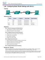
Lab - Configuring Multiarea OSPFv2
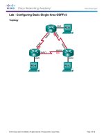
Topology
Addressing Table
Device
R1
R2
R3
Interface
IP Address
Subnet Mask
Lo0
209.165.200.225
255.255.255.252
Lo1
192.168.1.1
255.255.255.0
Lo2
192.168.2.1
255.255.255.0
S0/0/0 (DCE)
192.168.12.1
255.255.255.252
Lo6
192.168.6.1
255.255.255.0
S0/0/0
192.168.12.2
255.255.255.252
S0/0/1 (DCE)
192.168.23.1
255.255.255.252
Lo4
192.168.4.1
255.255.255.0
Lo5
192.168.5.1
255.255.255.0
S0/0/1
192.168.23.2
255.255.255.252
Objectives
Part 1: Build the Network and Configure Basic Device Settings
Part 2: Configure a Multiarea OSPFv2 Network
Part 3: Configure Interarea Summary Routes
© 2013 Cisco and/or its affiliates. All rights reserved. This document is Cisco Public.
Page 1 of 10
Lab - Configuring Multiarea OSPFv2
Background / Scenario
To make OSPF more efficient and scalable, OSPF supports hierarchical routing using the concept of areas.
An OSPF area is a group of routers that share the same link-state information in their link-state databases
(LSDBs). When a large OSPF area is divided into smaller areas, it is called multiarea OSPF. Multiarea OSPF
is useful in larger network deployments to reduce processing and memory overhead.
In the lab, you will configure a multiarea OSPFv2 network with interarea summary routes.
Note: The routers used with CCNA hands-on labs are Cisco 1941 Integrated Services Routers (ISRs) with
Cisco IOS Release 15.2(4)M3 (universalk9 image). Other routers and Cisco IOS versions can be used.
Depending on the model and Cisco IOS version, the commands available and output produced might vary
from what is shown in the labs. Refer to the Router Interface Summary Table at the end of this lab for the
correct interface identifiers.
Note: Make sure that the routers have been erased and have no startup configurations. If you are unsure,
contact your instructor.
Required Resources
3 Routers (Cisco 1941 with Cisco IOS Release 15.2(4)M3 universal image or comparable)
Console cables to configure the Cisco IOS devices via the console ports
Serial cables as shown in the topology
Part 1: Build the Network and Configure Basic Device Settings
In Part 1, you will set up the network topology and configure basic settings on the routers.
Step 1: Cable the network as shown in the topology.
Step 2: Initialize and reload the routers as necessary.
Step 3: Configure basic settings for each router.
a. Disable DNS lookup.
b. Configure device name, as shown in the topology.
c.
Assign class as the privileged EXEC password.
d. Assign cisco as the console and vty passwords.
e. Configure logging synchronous for the console line.
f.
Configure an MOTD banner to warn users that unauthorized access is prohibited.
g. Configure the IP addresses listed in the Addressing Table for all interfaces. DCE interfaces should be
configured with a clock rate of 128000. Bandwidth should be set to 128 Kb/s on all serial interfaces.
h. Copy the running configuration to the startup configuration.
Step 4: Verify Layer 3 connectivity.
Use the show ip interface brief command to verify that the IP addressing is correct and that the interfaces
are active. Verify that each router can ping their neighbor’s serial interface.
© 2013 Cisco and/or its affiliates. All rights reserved. This document is Cisco Public.
Page 2 of 10
Lab - Configuring Multiarea OSPFv2
Part 2: Configure a Multiarea OSPFv2 Network
In Part 2, you will configure a multiarea OSPFv2 network with process ID of 1. All LAN loopback interfaces
should be passive, and all serial interfaces should be configured with MD5 authentication using Cisco123 as
the key.
Step 1: Identify the OSPF router types in the topology.
Identify the Backbone router(s):
Identify the Autonomous System Boundary Router(s) (ASBR):
Identify the Area Border Router(s) (ABR):
Identify the Internal router(s):
Step 2: Configure OSPF on R1.
a. Configure a router ID of 1.1.1.1 with OSPF process ID of 1.
b. Add the networks for R1 to OSPF.
R1(config-router)# network 192.168.1.0 0.0.0.255 area 1
R1(config-router)# network 192.168.2.0 0.0.0.255 area 1
R1(config-router)# network 192.168.12.0 0.0.0.3 area 0
c.
Set all LAN loopback interfaces, Lo1 and Lo2, as passive.
d. Create a default route to the Internet using exit interface Lo0.
Note: You may see the “%Default route without gateway, if not a point-to-point interface, may impact
performance” message. This is normal behavior if using a Loopback interface to simulate a default route.
e. Configure OSPF to propagate the routes throughout the OSPF areas.
Step 3: Configure OSPF on R2.
a. Configure a router ID of 2.2.2.2 with OSPF process ID of 1.
b. Add the networks for R2 to OSPF. Add the networks to the correct area. Write the commands used in the
space below.
c.
Set all LAN loopback interfaces as passive.
Step 4: Configure OSPF on R3.
a. Configure a router ID of 3.3.3.3 with OSPF process ID of 1.
b. Add the networks for R3 to OSPF. Write the commands used in the space below.
c.
Set all LAN loopback interfaces as passive.
© 2013 Cisco and/or its affiliates. All rights reserved. This document is Cisco Public.
Page 3 of 10
Lab - Configuring Multiarea OSPFv2
Step 5: Verify that OSPF settings are correct and adjacencies have been established between
routers.
a. Issue the show ip protocols command to verify OSPF settings on each router. Use this command
to identify the OSPF router types and to determine the networks assigned to each area.
R1# show ip protocols
*** IP Routing is NSF aware ***
Routing Protocol is "ospf 1"
Outgoing update filter list for all interfaces is not set
Incoming update filter list for all interfaces is not set
Router ID 1.1.1.1
It is an area border and autonomous system boundary router
Redistributing External Routes from,
Number of areas in this router is 2. 2 normal 0 stub 0 nssa
Maximum path: 4
Routing for Networks:
192.168.1.0 0.0.0.255 area 1
192.168.2.0 0.0.0.255 area 1
192.168.12.0 0.0.0.3 area 0
Passive Interface(s):
Loopback1
Loopback2
Routing Information Sources:
Gateway
Distance
Last Update
2.2.2.2
110
00:01:45
Distance: (default is 110)
R2# show ip protocols
*** IP Routing is NSF aware ***
Routing Protocol is "ospf 1"
Outgoing update filter list for all interfaces is not set
Incoming update filter list for all interfaces is not set
Router ID 2.2.2.2
It is an area border router
Number of areas in this router is 2. 2 normal 0 stub 0 nssa
Maximum path: 4
Routing for Networks:
192.168.6.0 0.0.0.255 area 3
192.168.12.0 0.0.0.3 area 0
192.168.23.0 0.0.0.3 area 3
Passive Interface(s):
Loopback6
Routing Information Sources:
Gateway
Distance
Last Update
3.3.3.3
110
00:01:20
1.1.1.1
110
00:10:12
Distance: (default is 110)
© 2013 Cisco and/or its affiliates. All rights reserved. This document is Cisco Public.
Page 4 of 10
Lab - Configuring Multiarea OSPFv2
R3# show ip protocols
*** IP Routing is NSF aware ***
Routing Protocol is "ospf 1"
Outgoing update filter list for all interfaces is not set
Incoming update filter list for all interfaces is not set
Router ID 3.3.3.3
Number of areas in this router is 1. 1 normal 0 stub 0 nssa
Maximum path: 4
Routing for Networks:
192.168.4.0 0.0.0.255 area 3
192.168.5.0 0.0.0.255 area 3
192.168.23.0 0.0.0.3 area 3
Passive Interface(s):
Loopback4
Loopback5
Routing Information Sources:
Gateway
Distance
Last Update
1.1.1.1
110
00:07:46
2.2.2.2
110
00:07:46
Distance: (default is 110)
What is the OSPF router type for each router?
R1:
R2:
R3:
b. Issue the show ip ospf neighbor command to verify that OSPF adjacencies have been established
between routers.
R1# show ip ospf neighbor
Neighbor ID
2.2.2.2
Pri
0
State
FULL/
-
Dead Time
00:00:34
Address
192.168.12.2
Interface
Serial0/0/0
-
Dead Time
00:00:36
00:00:36
Address
192.168.12.1
192.168.23.2
Interface
Serial0/0/0
Serial0/0/1
-
Dead Time
00:00:38
Address
192.168.23.1
Interface
Serial0/0/1
R2# show ip ospf neighbor
Neighbor ID
1.1.1.1
3.3.3.3
Pri
0
0
State
FULL/
FULL/
R3# show ip ospf neighbor
Neighbor ID
2.2.2.2
c.
Pri
0
State
FULL/
Issue the show ip ospf interface brief command to display a summary of interface route costs.
R1# show ip ospf interface brief
Interface
Se0/0/0
PID
1
Area
0
IP Address/Mask
192.168.12.1/30
© 2013 Cisco and/or its affiliates. All rights reserved. This document is Cisco Public.
Cost
781
State Nbrs F/C
P2P
1/1
Page 5 of 10
Lab - Configuring Multiarea OSPFv2
Lo1
Lo2
1
1
1
1
192.168.1.1/24
192.168.2.1/24
1
1
LOOP
LOOP
0/0
0/0
Cost
781
1
781
State
P2P
LOOP
P2P
Nbrs F/C
1/1
0/0
1/1
Cost
1
1
781
State
LOOP
LOOP
P2P
Nbrs F/C
0/0
0/0
1/1
R2# show ip ospf interface brief
Interface
Se0/0/0
Lo6
Se0/0/1
PID
1
1
1
Area
0
3
3
IP Address/Mask
192.168.12.2/30
192.168.6.1/24
192.168.23.1/30
R3# show ip ospf interface brief
Interface
Lo4
Lo5
Se0/0/1
PID
1
1
1
Area
3
3
3
IP Address/Mask
192.168.4.1/24
192.168.5.1/24
192.168.23.2/30
Step 6: Configure MD5 authentication on all serial interfaces.
Configure OSPF MD5 authentication at the interface level with an authentication key of Cisco123.
Why is it a good idea to verify that OSPF is functioning correctly before configuring OSPF authentication?
Step 7: Verify OSPF adjacencies have been re-established.
Issue the show ip ospf neighbor command again to verify that adjacencies have been re-established after
MD5 authentication was implemented. Troubleshoot any issues found before moving on to Part 3.
Part 3: Configure Interarea Summary Routes
OSPF does not perform automatic summarization. Interarea summarization must be manually configured on
ABRs. In Part 3, you will apply interarea summary routes on the ABRs. Using show commands, you will be
able to observe how summarization affects the routing table and LSDBs.
Step 1: Display the OSPF routing tables on all routers.
a. Issue the show ip route ospf command on R1. OSPF routes that originate from a different area have a
descriptor (O IA) indicating that these are interarea routes.
R1# show ip route ospf
Codes: L - local, C - connected, S - static, R - RIP, M - mobile, B - BGP
D - EIGRP, EX - EIGRP external, O - OSPF, IA - OSPF inter area
N1 - OSPF NSSA external type 1, N2 - OSPF NSSA external type 2
E1 - OSPF external type 1, E2 - OSPF external type 2
i - IS-IS, su - IS-IS summary, L1 - IS-IS level-1, L2 - IS-IS level-2
ia - IS-IS inter area, * - candidate default, U - per-user static route
o - ODR, P - periodic downloaded static route, H - NHRP, l - LISP
+ - replicated route, % - next hop override
© 2013 Cisco and/or its affiliates. All rights reserved. This document is Cisco Public.
Page 6 of 10
Lab - Configuring Multiarea OSPFv2
Gateway of last resort is 0.0.0.0 to network 0.0.0.0
O IA
O IA
O IA
O IA
192.168.4.0/32 is subnetted, 1 subnets
192.168.4.1 [110/1563] via 192.168.12.2, 00:23:49, Serial0/0/0
192.168.5.0/32 is subnetted, 1 subnets
192.168.5.1 [110/1563] via 192.168.12.2, 00:23:49, Serial0/0/0
192.168.23.0/30 is subnetted, 1 subnets
192.168.6.1 [110/782] via 192.168.12.2, 00:02:01, Serial0/0/0
192.168.23.0/30 is subnetted, 1 subnets
192.168.23.0 [110/1562] via 192.168.12.2, 00:23:49, Serial0/0/0
b. Repeat the show ip route ospf command for R2 and R3. Record the OSPF interarea routes for each
router.
R2:
R3:
Step 2: Display the LSDB on all routers.
a. Issue the show ip ospf database command on R1. A router maintains a separate LSDB for every area
that it is a member.
R1# show ip ospf database
OSPF Router with ID (1.1.1.1) (Process ID 1)
Router Link States (Area 0)
Link ID
1.1.1.1
2.2.2.2
ADV Router
1.1.1.1
2.2.2.2
Age
1295
1282
Seq#
Checksum Link count
0x80000003 0x0039CD 2
0x80000002 0x00D430 2
Summary Net Link States (Area 0)
Link ID
192.168.1.1
192.168.2.1
192.168.4.1
192.168.5.1
192.168.6.1
192.168.23.0
ADV Router
1.1.1.1
1.1.1.1
2.2.2.2
2.2.2.2
2.2.2.2
2.2.2.2
Age
1387
1387
761
751
1263
1273
Seq#
0x80000002
0x80000002
0x80000001
0x80000001
0x80000001
0x80000001
© 2013 Cisco and/or its affiliates. All rights reserved. This document is Cisco Public.
Checksum
0x00AC1F
0x00A129
0x000DA8
0x0002B2
0x00596A
0x00297E
Page 7 of 10
Lab - Configuring Multiarea OSPFv2
Router Link States (Area 1)
Link ID
1.1.1.1
ADV Router
1.1.1.1
Age
1342
Seq#
Checksum Link count
0x80000006 0x0094A4 2
Summary Net Link States (Area 1)
Link ID
192.168.4.1
192.168.5.1
192.168.6.1
192.168.12.0
192.168.23.0
ADV Router
1.1.1.1
1.1.1.1
1.1.1.1
1.1.1.1
1.1.1.1
Age
760
750
1262
1387
1272
Seq#
0x80000001
0x80000001
0x80000001
0x80000001
0x80000001
Checksum
0x00C8E0
0x00BDEA
0x0015A2
0x00C0F5
0x00E4B6
Type-5 AS External Link States
Link ID
0.0.0.0
ADV Router
1.1.1.1
Age
1343
Seq#
Checksum Tag
0x80000001 0x001D91 1
b. Repeat the show ip ospf database command for R2 and R3. Record the Link IDs for the Summary Net
Link States for each area.
R2:
R3:
Step 3: Configure the interarea summary routes.
a. Calculate the summary route for the networks in area 1.
b. Configure the summary route for area 1 on R1.
R1(config)# router ospf 1
R1(config-router)# area 1 range 192.168.0.0 255.255.252.0
c.
Calculate the summary route for the networks in area 3. Record your results.
d. Configure the summary route for area 3 on R2. Write the commands you used in the space below.
Step 4: Re-display the OSPF routing tables on all routers.
Issue the show ip route ospf command on each router. Record the results for the summary and interarea
routes.
R1:
© 2013 Cisco and/or its affiliates. All rights reserved. This document is Cisco Public.
Page 8 of 10
Lab - Configuring Multiarea OSPFv2
R2:
R3:
Step 5: Display the LSDB on all routers.
Issue the show ip ospf database command again on each router. Record the Link IDs for the Summary Net
Link States for each area.
R1:
R2:
R3:
What type of LSA is injected into the backbone by the ABR when interarea summarization is enabled?
Step 6: Verify end-to-end connectivity.
Verify that all networks can be reached from each router. If any issues exist, troubleshoot until they have been
resolved.
Reflection
What are three advantages for designing a network with multiarea OSPF?
© 2013 Cisco and/or its affiliates. All rights reserved. This document is Cisco Public.
Page 9 of 10
Lab - Configuring Multiarea OSPFv2
Router Interface Summary Table
Router Interface Summary
Router Model
Ethernet Interface #1
Ethernet Interface #2
Serial Interface #1
Serial Interface #2
1800
Fast Ethernet 0/0
(F0/0)
Fast Ethernet 0/1
(F0/1)
Serial 0/0/0 (S0/0/0)
Serial 0/0/1 (S0/0/1)
1900
Gigabit Ethernet 0/0
(G0/0)
Gigabit Ethernet 0/1
(G0/1)
Serial 0/0/0 (S0/0/0)
Serial 0/0/1 (S0/0/1)
2801
Fast Ethernet 0/0
(F0/0)
Fast Ethernet 0/1
(F0/1)
Serial 0/1/0 (S0/1/0)
Serial 0/1/1 (S0/1/1)
2811
Fast Ethernet 0/0
(F0/0)
Fast Ethernet 0/1
(F0/1)
Serial 0/0/0 (S0/0/0)
Serial 0/0/1 (S0/0/1)
2900
Gigabit Ethernet 0/0
(G0/0)
Gigabit Ethernet 0/1
(G0/1)
Serial 0/0/0 (S0/0/0)
Serial 0/0/1 (S0/0/1)
Note: To find out how the router is configured, look at the interfaces to identify the type of router and how many
interfaces the router has. There is no way to effectively list all the combinations of configurations for each router
class. This table includes identifiers for the possible combinations of Ethernet and Serial interfaces in the device.
The table does not include any other type of interface, even though a specific router may contain one. An
example of this might be an ISDN BRI interface. The string in parenthesis is the legal abbreviation that can be
used in Cisco IOS commands to represent the interface.
© 2013 Cisco and/or its affiliates. All rights reserved. This document is Cisco Public.
Page 10 of 10