Chế tạo và nghiên cứu tính chất quang học của vật liệu tio2 có cấu trúc nano pha tạp ion đất hiếm tt tiếng anh
Bạn đang xem bản rút gọn của tài liệu. Xem và tải ngay bản đầy đủ của tài liệu tại đây (2.31 MB, 24 trang )
ACKNOWLEDGMENT OF THE AUTHOR
I guarantee this is my own research work, conducted under the guidance of Associate Professor
Nguyen Manh Son, at the Department of Physics, University of Sciences, Hue University. The data and
results of the thesis are guaranteed to be accurate, truthful and have never been published in any other works.
I also certify that I do not submit this PhD thesis to any other training institution for a degree.
In: Hue, Vietnam
On:
Signature:
SUMMARY
Due to many anomalous properties and its applicability in various fields, nano-sized TiO2 has been
of interest to scientists. Nano TiO2 is an important agent in photocatalytic [7], [28], converting solar energy
into electrical energy [26], [27], photosynthesis of water into hydrogen fuel [21], [ 32], [66], [88].
With its high thermal stability, durability, non-toxicity and outstanding optical properties, nanostructure TiO2 is considered a potential new substrate for doping rare earth ions (RE). The transfer of energy
from nano TiO2 to rare earth ions is made easier because they have many energy levels. For example, 5D1 →
7
F1, 5D0 → 7FJ transitions (J = 0, 1, 2, 3, 4) of Eu3+ ions will emit radiation in the visible region at 543, 579,
595, 615, 655 and 701 nm [73], [81]. Because TiO2 has many polymorphs and RE ions have a special
electronic structure, therefore, studying their luminescent properties will bring new information.
Thus, the study of the above issues is not only scientifically significant but also practical. So far, the
question of the energy transfer mechanism between TiO2 network with different crystal structure and RE
ions, as well as the position of RE ions in TiO2 network is still questionable. The inverted fluorescence effect
(for Stocks) of RE ions in the nano TiO2 network is an attractive research object [44], [87]. Nanomaterials
are characterized by physical and chemical properties that depend on size and structure. Meanwhile, size,
structure and its applicability depend on manufacturing technology. Therefore, to be proactive in researching
and applying properties of materials in real life, we focus on developing technology to product nano TiO 2 by
ultrasonic – hydrothermal, and sulfuric acid methods. These are simple methods of synthesizing materials,
low cost, suitable for laboratory conditions of training institutions.
For the above reasons, we chose the thesis topic: “Synthesis and investigation optical properties
of TiO2 nanostructure doped with earth rare ions”.
The research object is nano structure TiO2 material doped with the rare earth ions. Research content
includes:
Basic research:
Research and fabricate rare earth TiO2 nanoparticles with sulfuric acid method and ultrasonic hydrothermal method.
Study the effect of manufacturing conditions on the structure, microstructure and spectral properties
of RE3+ TiO2 doped materials when heated at different temperatures.
Study the energy transfer effect between TiO2 network and trigger centers.
Study the fluorescent effect of nanoTiO2 doped RE.
Calculate and simulate the energy band structure of TiO2, nano TiO2 doped RE by the density
function theory (DFT).
Application development research, We focus on photocatalytic ability of TiO2 nano and doped
TiO2 materials. The theoretical and practical meanings are reflected in the achieved results. The thesis
1
systematically presents research results on the physical properties of nano TiO 2 materials doped with rare
earth ions. The results of the thesis are new contributions in terms of basic research and application of this
material.
The main contents of the thesis are presented in 4 chapters.
Chapter 1. Overview of theory;
Chapter 2. Manufacturing technology, structure, microstructure of TiO2 nano materials doped rare
earth ions (Eu3+, Sm3+);
Chapter 3. Spectroscopic characteristic of TiO2 nanoparticles doped RE3+ ions;
Chapter 4. Application of nano TiO2 in photocatalytic;
CHAPTER 1
LITERATURE REVIEW
1.1. OVERVIEW OF NANO – STRUCTURED TiO2
1.1.1. Introduction of nano-structured TiO2
1.1.1.1. The structural forms and physical properties of TiO2
TiO2 are a typical semiconductor, formed at high temperatures when Ti reacts with O. The most
typical and stable oxidation state of Ti is + 4 (TiO2) due to Ti4 + ions having a durable configuration of
noble gases (18 electrons). In addition, Ti can exist in the lower oxidation states of +2 (TiO) and +3 (Ti 2O3),
but it is easier to switch to a more stable +4 state.
Depending on the fabrication conditions, TiO2 can have anatase, rutile, brookite or all three types of
polymorphic structure, in which the anatase and rutile structures are the most common (Figure 1.1).
Figure 1. 1. Anatase and rutile structure of TiO2
These two structures differ due to the deformation of each octahedron and the way in which the
octahedra are connected. Each Ti4+ ion is in an octahedron surrounded by 6 O2- ions. The octahedral mass
corresponding to the rutile phase is uneven due to the weak diamond face deformation, while, the octahedral
of the anatase phase is strongly deformed. Therefore, the symmetry of the anatase system is lower than the
symmetry of the rutile system. Differences in the network structure of TiO 2 create differences in density,
energy region structure and a range of other physical properties between anatase and rutile phases.
1.1.1.2. Energy band structure of TiO2
TiO2 is a semiconductor with a relatively large band gap, the valence band filled with electrons, and
the blank conductivity. TiO2 in the anatase phase has a band width of 3.2 eV, which corresponds to the
2
energy of a light quantum with a wavelength of about 388 nm, while TiO 2 rutile phase has a band width of
3.0 eV corresponding to the energy amount of a light quantum with a wavelength of about 413 nm.
Vùng dẫn
Vùng dẫn
Vùng cấm
Vùng cấm
λ ≤ 388 nm
λ ≤ 413 nm
e-
e-
e-
e-
Vùng hóa trị
Vùng hóa trị
Anatase
Rutile
Figure 1.3. Diagram of the energy band structure of TiO2
1.1.1.3. Applications of nano TiO2
+ Application in the field of photocatalyst
Due to its extremely strong photocatalytic effect, nano-sized TiO2 is effectively used to treat the
environment [18], [57], [60].
+ Application of color-sensitive solar cells (DSSC)
TiO2 can absorb light in the visible region and convert solar energy into electrical energy for applications in
solar cells [11], [26], [62].
+ Application in biomedical
One-dimensional structural nano TiO2 has recently been investigated for biomedical applications such as
drug delivery, biomarking and construction of artificial tissues [6], [40], [65], [68]. Using nanotubes or TiO 2
nanowires both ensures porosity and antibacterial ability to enhance the interaction between bone cells and
titanium.
1.1.2.
Fabrication methods of nano TiO2
1.1.2.1. Hydrothermal method
Hydrothermal method is the method of using solutions under high temperature and pressure
conditions to increase the solubility and reaction speed between substances. To do this, the material
dissolution solution is placed in an autoclave and heated, usually using autoclave device. The method using
TiO2 with different agents (such as NaOH, KOH, LiOH, ...) will give products with single structure, small
size (size 10 nm to 30 nm) and large surface area [ 23], [67], [73], [81].
1.1.2.2.
Sol – gel method
The sol - gel method is the process of converting sol into gel with two stages: sol and gel generation.
Synthesis of nano TiO2 by this method we can obtain materials with the desired state such as mass, embryo
film, fiber and powders of uniform size [10], [31], [53], [58 ], [71], [77].
1.1.2.3.
Microwave method
3
When using the microwave method, the heat addition by creating molecular vibrations at very high
speed. Rapid and uniform heating, which is similar to hydrothermal processes at high temperatures. Heat is
generated by friction between molecules and the conversion of microwave energy into heat. The advantage
of this method is that the synthesis is fast, simple and easy to repeat [84].
1.1.2.4.
Ultrasonic method
The methods using ultrasound waves (called ultrasound method for short) are new approaches
developed in recent years [74]. This method uses high-power ultrasound source to create chemical reactions
through the cavitation effect.
1.1.2.5.
Electrochemical method
The electrochemical method is an important method in the synthesis of TiO2 nanotubes in tubes,
fibers or films [80], [54], [52]. In general, the electrochemical method has good control over the shape and
size of nano TiO2 materials by creating anodic molding.
1.2. OPTICAL CHARACTERISTICS OF RARE EARTH IONS
1.2.1. Overview of rare earth elements
Rare-earth elements (RE) are elements of the Lanthan group, characterized by the 4f-filled electronic
layer shielded by the outer-filled electronic layer of 5s2 and 2p6. Therefore, the effect of the master lattice
field on the optical shifts in the 4f n configuration is small (but necessary).
Rare-earth elements: Ce, Pr, Nd, Pm, Eu, Gb, Tb, Dy, Ho, Er, Tm, Yb have atomic numbers from 58
to 70 which play a very important role in the luminescence of crystals. Diagram of the energy level structure
of valence rare earth ions, also called Dieke diagram (Figure 1.4).
Figure 1.1. Energy level diagram of RE3+ ions - Dieke diagram
1.2.2.
Optical characteristics of Europium and Samarium
1.2.2.1. Optical characteristics of Europium
4
Europium (Eu) is a rare earth element of the Lantanite family in the 63rd cell (Z = 63) in the Mendeleev periodic
table. Europium usually exists in the form of valence 2 and valence oxides, but in the trivalent form (Eu2O3) is more
common. Electronic configuration of atoms and ions:
Eu:
1s22s22p6…(4f7)5s25p66s2
Eu2+:
1s22s22p6….. (4f7)5s25p6
Eu3+:
1s22s22p6….. (4f6)5s25p6
The emission spectra of Eu2+ ions and of Eu3+ ions are shown in Figure 1.5.
Figure 1. 2. The emission spectra of Eu2+ ions and Eu3+ ion.
1.2.2.2. Optical characteristics of Samarium
Samarium (Sm) is a rare earth element of the Lantanite family located in the 62nd cell (Z = 62) in the Mendeleev
periodic table. Samarium usually exists in the form of Sm2O3¬ oxide, a solid crystalline structure, pale yellow, with a
cubic structure. Electronic configuration of atoms and ions:
Sm (Z=62): 1s22s22p6…(4f6)5s25p66s2
Sm3+: 1s22s22p6 …(4f5) 5s25p6
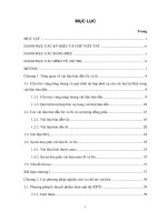
The emission spectra of Sm3+ ion is located in the orange-red region, corresponding to transitions: 4G5/26HJ (J =
5/2; 7/2; 9/2; 11/2; 13/2; 15/2) (figure 1.6).
3.5
4
6
G5/2- H7/2
TiO2:Sm
3.0
3+
ex: 365 nm
4
2.5
6
G5/2- H5/2
2.0
1.5
4
6
G5/2- H9/2
1.0
0.5
4
6
G5/2- H11/2
0.0
550
575
600
625
650
675
700
725
750
Hình 1. 3. The emission spectra of Sm3+ doped nanoTiO2
1.3. OVERVIEW OF THE RESEARCH PROCESS OF NANO TiO2 AND RE DOPED NANO TiO2
1.3.1.
Research situation in the country
Nano TiO2 materials are very much interested in research by domestic scientists. The research
focuses on developing manufacturing methods, photocatalyst capabilities, sensor fabrication applications,
5
solar cells, biomedical materials. The group of authors Truong Van Chuong and Le Quang Tien Dung of the
University of Science - Hue University used ultrasound - hydrothermal methods to synthesize fiber materials
of a few tens of nanometers to apply in photocatalytic photocatalysis. destroy methylene blue [1]. Nguyen
Thi Mai Huong and her colleagues studied the effect of porosity on the self-cleaning effect of thin nano TiO2
thin film. The author Mac Nhu Binh and his team synthesized Ago-doped TiO2 material for bactericidal
Vibrio Alginolyticus in shrimp [2]. Authors Nguyen Thi Thanh Loan, Tran Quang Vinh, Nguyen The Anh,
Nguyen Thi Thu Trang, Nguyen Thi Nghiem, Bui Duy Du, Tran Thi Ngoc Dung, Nguyen Thuy Phuong,
Chu Quang Hoang, Le Thi Hoai Nam research and manufacture Doped TiO2 Ag application for bactericidal
E. Coli [3]. The authors of Thai Thuy Tien, Le Van Quyen, Au Van Tuyen, Ha Hai Nhi, Nguyen Huu Khanh
Hung, Huynh Thi Kieu Xuan studied synthesizing TiO2 nanotubes by electrochemical method applied in
photocatalyst [4]. Only Le Viet Phuong, Nguyen Duc Chien and Do Phuc Hai (ITIMS) have studied the
optical properties of Ca1-xEuxTiO3 red light-emitting material.
The study optical properties of rare earth ions on nano TiO2 has not been much researched in
Vietnam.
1.3.2.
Research situation of scientific issues abroad
Nano TiO2 materials are very much interested in research by many scientists around the world. Since
1994, D. Philip Colombo et al. Synthesized nano TiO2 by sol - gel method [55]. With many outstanding
physical properties, especially when doped into this network, some metal or nonmetal ions to change the
structure as well as geometry, nano TiO2 has brought many practical applications. In 1997, Md. Mosaddequr-Rahman et al. Synthesized lead-doped nano TiO2 (Pb) for solar cell fabrication applications [51]. Shi-Jane
Tsai, Soofin Cheng studied photocatalyst properties of nano TiO2 to decompose phenolic [69]. In the
following years, nano TiO2 was soon applied in other fields such as making electrodes for electronics and
biomedical applications [13], [41]. In addition, scientists have sought to manipulate the size and geometry of
nanomaterials to meet specific research objectives in basic and applied research. Although researched and
applied very early in many fields, but today, nano TiO2 is still an attractive and topical research object.
In 2007 Jie Zhang, Xin Wang, Wei-Tao Zheng, Xiang-Gui Kong, Ya-Juan Sun and Xin Wang
studied the fabrication of Er3+ doped nano TiO2 by chemical method combining heat treatment in different
modes. . The authors obtained TiO2 material: Er3+ hollow sphere. As the heat treatment time increases, the
thickness and smoothness of the shell increases, the connection between the orbs increases. When heated to
8000C, transfer phase anatase - rutile formed in TiO2 material. However, they do not occur in Er3+ doped
TiO2 material. This result shows that Er3+ ions play an important role in preventing this phase transition [83].
In 2008, Quingkun Shang and colleagues studied the reverse conversion effect of Eu3+ - Yb3+ in
nano-TiO2 based fabrication by sol-gel method. The authors found two emission bands in the region of 520 570 nm (2H11/2, 4S3/2 - 4I15 / 2) and 640 - 690 nm (4F9 / 2 - 4I15 / 2) when stimulated by wavelength laser
980 nm [64]. Chenguu Fu studied the fluorescence spectrum of Er3+ doped TiO2 by wet chemical method.
The author has observed relatively strong narrow line luminescence in the infrared region of about 1.53 μm.
The author states that it is the luminescence of the Er3+ ion occupying the lattice position in the nano TiO2
crystal and is the result of the energy transfer from the TiO2 background lattice to this spurious [15].
In 2017, Vesna ĐorđevićBojana, Bojana Milicevic and Miroslav D. Dramicanin published an indepth overview of TiO2 nano manufacturing methods and optical properties of nano TiO2 doped with rare
earth ions [72]. This report has shown that introducing trivalent rare earth ions into the nano TiO 2 network
has changed the structure and some physical properties of the system. In addition, because TiO2 (anatase)
6
with a band gap of about 3.2 eV, while the energy gap (from the ground state to the lowest stimulus level) of
rare earth ions is relatively large, there is only one rare earth (Nd3+, Sm3+, Eu3+, Ho3+, Er3+, Tm3+, Yb3+) when
doped into this substrate causes luminescence phenomenon.
CHAPTER 2
MANUFACTURE TECHNOLOGY, STRUCTURE AND MICROSTRUCTURE OF RARE EARTH
(Eu3+, Sm3+) DOPED NANO TIO2 MATERIAL
2.1. SYNTHESIS NANO TiO2 MATERIAL
2.1.1. Synthesis of nano TiO2 by ultrasonic - hydrothermal method
Using hydrothermal ultrasound method to synthesize nano TiO2 has been interested in research by
domestic and foreign scientists because this method has many outstanding advantages, simple manufacturing
process, and easy to repeat. The structure of the material after fabrication is in the form of nanotubes or
nanorods with sizes of several nanometers.
Add TiO2 powder (anatase, Merck 98%) to 16 M NaOH solution (Merck) by ratio TiO2: NaOH = 1:
2 ratio. The mixture is dispersed by ultrasonic power of 100W during 30 minute. The mixture was
hydrothermal at 150°C for 16 hours. The mixture after hydrothermal process is neutralized with 0.1 M HCl
solution, then washed several times to remove unwanted components and dried at 70 ° C for 24 hours. The
final product obtained is TiO2.nH2O which is thermal treatmented at different temperatures between 250°C
and 950°C for 2 hours.
2.1.2. Synthesis of nano TiO2 by using sulfuric acid method
The mixture of TiO2 and H2SO4 solution (98%) in the ratio TiO2 (g): H2SO4 (mL) = 1: 2 is dispersed
by ultrasonic power of 100W for 15 minutes, then Heat at 100oC for 1h. After being heated, the mixture is
hydrolyzed and neutralized with NH4OH solution to a pH of 8, creating a white precipitate, and then washed
several times to remove unwanted components. then dry at 70oC for 24 hours. The final product obtained is
TiO2.nH2O powder. This powder is processed at temperatures between 250oC and 1000oC for 2 hours.
2.1.3. Fabrication of RE doped nano TiO2 materials
RE3+ ion-doped TiO2 nanomaterials are fabricated in 2 steps.
+ Fabrication of nano TiO2 solution. Add 0.5 gram of TiO2.nH2O powder to a mixture of 20 ml of
H2O2 solution and 10 ml of NH4OH. When TiO2 is completely dissolved, add 20 ml of H2O.
+ Fabrication of nano TiO2 doped RE3+ ions. Dissolve RE2O3 in HNO3 solution with a sufficient
amount of distilled water to obtain a 0.01 M salt solution. Finally, add Eu(NO3)3 or Sm(NO3) 3 solution to
TiO2 solution with different concentration ratios (RE3+ / (Ti + RE)) (from 0.1% mol to 15% mol). . The
mixture is then stirred with magnetic stirrer combined with heating to regain the mixture in powder form.
This powder is heat-treated at different temperatures (from 350oC to 950oC) for 2 hours.
2.2. STRUCTURE AND MICROSTRUCTURE OF RE DOPED NANO TiO2
2.2.1. Structure and microstructure of nano TiO2
2.2.1.1. Microstructure of nano TiO2
Nano TiO2 materials after fabrication by ultrasonic - hydrothermal method and the method of using
sulfuric acid with sizes from several nm to several tens of nm are shown by TEM anhier in Figures 2.5 and
2.6. The shape and dimensions of the samples depend on the technological conditions and the fabricating
material method.
.
7
Figure 2. 1. TEM image of nano TiO2 prepared by ultrasonic - hydrothermal method at 550oC for 2 hours
Figure 2. 2. TEM image of nano TiO2 prepared by using sulfuric acid calcined at 550oC for 2 hours
From TEM images in Figures 2.5 and 2.6, it has been shown that TiO2 is synthesized by both
methods with high uniformity, ranging in size from a few nm to several tens of nm. Samples fabricated by
hydrothermal method have the form of nano bar. While, samples manufactured using sulfuric acid are
spherical in shape.
2.2.1.2. The crystal structure of nano TiO2
Usually, the crystal structure of a material depends on technological factors such as sample heating
temperature and manufacturing method. The following is an X-ray diffraction diagram of samples heated at
different temperatures from 250°C to 950°C for 2 hours.
A - anatase
R - rutile
R
R
R
R
R
A
o
A
950 C
A
o
850 C
o
750 C
A
A
A
o
650 C
o
550 C
o
450 C
o
350 C
o
250 C
20
30
40
50
60
70
80
90
Gãc nhiÔu x¹ 2 theta (®é)
Figure 2. 3. X-ray diffraction diagram of nano TiO2 fabricated by ultrasonic - hydrothermal method
8
A
A - anatase
R - rutile
A - anatase
R - rutile
R
R
R
A
R
A
AA
A
AA
R
R
A
o
o
1000 C
650 C
o
550 C
o
950 C
o
450 C
o
850 C
o
350 C
o
o
750 C
250 C
20
30
40
50
60
70
80
90
20
30
Gãc nhiÔu x¹ (2 theta)
40
50
60
70
80
90
Gãc nhiÔu x¹ (2 theta)
Figure 2. 9. X-ray diffraction diagram of nano TiO2 fabricated by by using sulfuric acid method
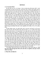
X-ray diffraction diagrams in Figures 2.8 and 2.9 show that, when the sample heating temperature is
lower than 350°C, the nano TiO2 samples have an amorphous structure, when the temperature ranges from
350°C to less than 650°C the nano TiO2 particles have crystal anatase phase structure characterized by
diffraction peaks at angles 2θ equal 25,28o; 37.78o; 48.05o; 54.1o; 55.01o; 62,61o; 68.9o; 70.7o and 75.3o have
Miller numbers, respectively (101), (004), (200), (105), (211), (204), (116), (220) and (215) [7], [17], [70],
[50], [79], [82], [76], [9]. When the calcination temperature of the sample is about 650 oC, the rutile phase is
formed which is characterized by diffraction peaks at 2θ equal 27.41; 36.05; 41.34; 54.32; and 68.99,
respectively, with Miller indexes (110), (101), (111), (211), and (301) [70], [50], [82], [76The ratio of
anatase phase, XA, in the material is calculated by equation (2.1) [23], [50]:
(2.1)
( )
where IA, IR correspond to the intensity of the anatase peak (101), the diffraction angle 2θ corresponds to
25,28o and rutile (110), the diffraction angle 2θ corresponds to 27,41o.
On the other hand, with an increase in temperature, the half-width of the diffraction peaks
corresponding to the (101) and (110) surfaces decreases. This proves that the crystal size increases with
increasing sample processing temperature. The crystal size of a material is calculated using the Debye Scherrer equation [7], [33], [50], [76], [81]
(2.2)
where
is a constant with a value of 0.89 (in case of fabrication by hydrothermal method) and 0.9
(fabricated by acid method));
1,5406 Å),
is the wavelength of X-ray radiation (
diffraction peak (101) for the anatase phase and (110) for the rutile phase,
is the half-width of
is the diffraction angle
corresponding to the vertices (101) and (110).
The phase ratio and particle size of materials manufactured by two different methods are shown in
Tables 2.1 and 2.2.
Table 2.1. The ratio of anatase phase (XA), rutile (XR) and crystal size (D) of TiO2 are synthesized by
ultrasonic - hydrothermal method
o
Temperature ( C)
350
450
550
650
750
850
950
( )
100
100
100
88.9
40.6
21
0
( )
0
0
0
11.1
59.4
79
100
7.2
8.4
10.2
14.1
45.3
64.8
68.9
9
Table 2.2. The ratio of anatase phase (XA), rutile (XR) and crystal size (D) of TiO2 are synthesized by using
sulfuric acid method
o
Temperature ( C)
350
450
550
650
750
850
950
( )
100
100
100
94.9
70.6
37.5
1.3
( )
0
0
0
5.1
29.4
62.5
98.7
5.8
7.6
8.8
12.4
44.2
61.9
63.1
For further study of the structure of fabricated materials, we also use Raman spectrometry. Figure
2.11 is the Raman spectrum by temperature of TiO2 nano fabricated by the two above methods.
o
o
TiO2 350 C
(a)
TiO2 350 C
(b)
o
TiO2 550 C
o
TiO2 550 C
o
o
TiO2 750 C
TiO2 750 C
o
o
TiO2 850 C
TiO2 850 C
o
o
TiO2 950 C
TiO2 1000 C
447
447
637
609
609
637
394
100
200
294
516
235
300
400
500
516
235
600
-1
700
800
900
100
200
300
400
500
600
-1
700
800
900
DÞch chuyÓn Raman (cm )
DÞch chuyÓn Raman (cm )
Figure 2. 4. The Raman spectrum of TiO2 is made by ultrasonic - hydrothermal method (a), sulfuric acid
method (b)
From the Raman spectra, we found that for the TiO2 samples heated at 350°C and 550°C the Raman
peaks appeared at 144.1; 198; 394.4; 516 and 637.7 cm-1 correspond to the Eg, Eg, B1g, A1g, and Eg
oscillation modes of the anatase phase. For samples calcined at 950°C, Raman peaks appear at 142; 447 and
609 cm-1 correspond to the vibration modes B1g, Eg, and A1g of the rutile phase, the mode at 235 cm-1
corresponds to the lattice vibrations of many phonons (Figure 2.12) [82], [76], [33], [24], [34], [43], [12],
[61]. The Raman analysis results are completely consistent with the X-ray diffraction analysis as presented.
Figure 2. 5. Absorption spectrum of TiO2 samples according temperature
Figure 2.13 is the UV-Vis absorption spectra of TiO2 prepared by method of using sulfuric acid.
From here, it is allowed to determine the band gap of the material according to Kubelka Munk theory [19],
[46], [59], [63]. The results of calculating the band gap of TiO2 samples are listed in Table 2.3.
10
Table 2. 3. Energy band gap of TiO2
o
Temperature ( C)
(eV)
350
550
750
950
3.17
3.15
3.12
2.87
2.2.2. Structure, microstructure of RE3+ doped nano TiO2
2.2.2.1. Microstructure of of RE3+ doped nano TiO2
TEM image of 1% molar TiO2 doped Ti: Eu and TiO2 doped with 1% mol Sm3+ calcined at 500oC is
shown in Figures 2.14 and 2.15. TEM images show that the samples are about 10 to 20 nm in size. This is
consistent with the result of calculating particle size from diffraction spectrum by the Debye - Scherrer
equation.
Figure 2. 6. TEM images of TiO2:Eu3+ (1% mol) calcined at 500oC taken at different positions
Figure 2. 7. TEM images of TiO2:Sm3+ (1% mol) calcined at 500oC taken at different positions
Morphologically, RE-doped samples are generally spherical in shape similar to un-doped samples.
The Eu
3+
doped samples show clumping and the image of particles is not clear. Whereas, the Sm3+ doped
samples have a very clear image, the separated particles are more like the less doped samples.
2.2.2.2. The crystal structure of the RE doped nano TiO2
The crystal structure of the RE doped nano TiO2 material was investigated through X-ray diffraction
(XRD), Raman spectrometry and UV-Vis absorption spectrometry at room temperature. X-ray diffraction
measurement of Eu3+ and Sm3+ doped samples heated at 550oC with a concentration of 0.1% mol to 6% mol
is depicted in Figure 2.16.
11
Figure 2. 8. X-ray diffraction diagram of TiO2:Eu3+ (a), TiO2:Sm3+ (b) according to the doped concentration
is calcined at 550oC for 2 hours
A - anatase
R - rutile
R
TiO2:Eu
(a)
A - anatase
R - rutile
A
3+
(b)
3+
TiO2:Sm
R
A
R
R
R
RA
o
950 C
A
R
o
A
A
AA
850 C
o
A
o
950 C
o
AA
850 C
A
R
o
750 C
750 C
o
650 C
o
650 C
o
550 C
o
550 C
o
450 C
20
25
30
35
40
45
50
55
60
Gãc nhiÔu x¹ 2 (®é)
65
70
75
80
o
450 C
20
25
30
35
40
45
50
55
60
65
70
75
80
Gãc nhiÔu x¹ 2 (®é)
Figure 2. 9. X-ray diffraction diagram of TiO2: Eu3+ (1% mol) (a), TiO2: Sm3+ (1% mol) (b) heated from
450oC to 950oC
From the X-ray diffraction scheme, it is shown that samples heated at 450°C are mostly amorphous.
Meanwhile, un-doped TiO2 samples have anatase structure. When increasing the temperature of sample
heating, TiO2 doped materials with 1% mol Eu3+ and TiO2 doped with 1% mol Sm3+ have anatase phase
crystal structure with increasing crystallinity with calcination temperature. Eu3+ doped samples have higher
anatase phase crystallinity. When the calcination temperature reaches 750oC, there is the appearance of rutile
phase. From the temperature range of 750oC to 950oC, the Eu3+ and Sm3+ doped samples have a crystal phase
structure, which is a mixture of anatase and rutile phases. Eu3+ doped samples have higher rutile crystallinity
than Sm3+ doped samples. This is shown by the observation that at the same firing temperature, the peak at
27.41° corresponds to the lattice (110) of the rutile phase of the Eu3+ doped samples than the Sm3+ doped
samples. In addition, we also use the Debye - Scherrer equation to calculate the particle size for the above
samples. Anatase - rutile phase ratio and crystal size are listed in Table 2.4:
12
Table 2. 4. Percentage of anatase-rutile phase and particle size of TiO2, TiO2: Eu3+ (1% mol) and
TiO2: Sm3+ (1% mol) according to sample heating temperature
Temperature
Crystal size (nm)
XA (%)
TiO2:Eu
TiO2:Sm
TiO2:Eu
TiO2:Sm
(1 % mol)
(1 % mol)
(1 % mol)
(1 % mol)
550
7,9
6,9
100
100
650
9,8
8,7
100
100
750
14,7
10,8
90,1
93,2
850
45,1
26,4
72,1
80,1
950
58,6
45,9
19,6
66,7
In general, compared with undoped TiO2 samples (Table 2.2) at the same firing temperature, the
doped TiO2 samples are significantly smaller in size. The anatase phase crystallinity as well as the rutile of
the doped samples are also lower. From this, it can be concluded that doping of rare earth ions (namely Eu 3+
and Sm3+) limits the growth of particle size and prevents the formation of crystal phase structure of TiO2
nano. In addition, comparing the Raman spectrum of TiO2 doped with rare earth ions (Eu3+, Sm3+), shown in
Figure 2.18 with the Raman spectrum of TiO2 not doped (Figure 2.11), the location of Raman peaks has
some changes. small due to the influence of impurity ions on the crystal structure of the substrate. Eu 3+
doped samples basically have less deviation modes than the Sm3+ doped samples, due to the location of rare
earth ions (Eu3+ and Sm3+) located at different positions in the crystal lattice.
550 1% mol Eu-TiO2
650 1% mol Eu-TiO2
850 1% mol Eu-TiO2
950 1% mol Eu-TiO2
(a)
550-1% mol Sm:TiO2
650-1% mol Sm:TiO2
850-1% mol Sm:TiO2
950-1% mol Sm:TiO2
(b)
637
637
609
394
447
609
294
516
447
516
235
100
200
235
300
400
500
600
700
800
900
100
200
DÞch chuyÓn Raman (cm-1)
300
400
500
600
700
800
900
-1
DÞch chuyÓn Raman (cm )
Figure 2. 10. Raman spectrum of nano TiO2 doped with 1% mol Eu3+ (a), 1% mol Sm3+ (b), the samples
were calcined from 550oC to 950oC
Samples heated under 450°C have an amorphous structure, when the sample heating temperature
ranges from 550°C to less than 750°C, modes appear around 145, 394, 516 and 637 cm-1 corresponding to
the fluctuating modes. of anatase phase. The samples were heated at 850°C and 950°C. In addition to the
above modes, there were modes of oscillation at positions 235, 447 and 609 cm-1 corresponding to the rutile
phase. Thus, the information obtained from the Raman spectrum is completely consistent with the results of
X-ray diffraction analysis discussed in the previous section.
To study the effect of doping on the energy region structure of RE doped TiO 2, UV-Vis absorption
spectra of Eu and Sm doped TiO2 nano were investigated. The absorption spectra of 1% mol Eu3+ doped
TiO2 and 1% Sm doped TiO2 samples heated at different temperatures are shown in Figures 2.19 and 2.20.
13
o
o
TiO2 350 C-1% mol
o
TiO2 550 C-1% mol
o
TiO2 750 C-1% mol
TiO2 350 C-1% mol
o
TiO2 550 C-1% mol
o
§é hÊp thô (®vt®)
TiO2 750 C-1% mol
o
§é hÊp thô (®vt®)
TiO2 950 C-1% mol
TiO2:Eu
400
450
3+
500
550
600
650
o
TiO2 950 C-1% mol
TiO2:Eu
1.90
700
2.09
3+
2.28
2.47
2.66
2.85
3.04
3.23
3.42
Figure 2. 11. The absorption spectrum of TiO2: Eu3+ (1% mol) heated from350oC to 950oC
o
TiO2 350 C-1% mol
o
TiO2 350 C-1% mol
o
TiO2 550 C-1% mol
o
TiO2 550 C-1% mol
o
TiO2 750 C-1% mol
o
TiO2 750 C-1% mol
o
3+
TiO2:Sm
400
450
500
550
600
650
700
o
§é hÊp thô (®vt®)
§é hÊp thô (®vt®)
TiO2 950 C-1% mol
TiO2 950 C-1% mol
TiO2:Sm
2.04
2.21
3+
2.38
2.55
2.72
2.89
3.06
3.23
3.40
N¨ng l-îng (eV)
Hình 2. 12. The absorption spectrum of TiO2: Eu3+ (1% mol) heated from 350oC to 950oC
From the absorption spectrometry results shown in Figures 2.19 and 2.20, it shows that when the
sample heating temperature increases, the absorption spectrum of the diluted TiO 2 samples is towards the
long wavelength compared to the undoped samples. Eu3+ doped samples strongly absorb in the wavelength
range from 370 nm to 410 nm. Samples heated at 350°C have an absorption band of about 375 nm, while
samples heated at 950°C have an absorption band of about 410 nm. Therefore, the band width of the rare
earth doped samples decreases compared to the un-doped samples. However, the change in band gap of 1%
mol Eu3+ doped TiO2 samples was less than 1% mol Sm3+ doped TiO2 samples at the same sample heating
temperature. That change is shown in Table 2.5.
Table 2. 5. The band gap of TiO2:Eu3+ (1% mol) and TiO2:Sm3+ (1% mol) calcined from 350oC to 950oC
Temperature (oC)
Band gap (eV)
TiO2
3+
TiO2:Eu (1% mol)
TiO2:Sm3+ (1% mol)
350
3,17
3,06
2,98
550
3,15
3,00
2,95
750
3,12
2,95
2,92
950
3,87
2,81
2,80
The results in Table 2.5 show that the doping of rare earth ions reduces the band gap of TiO 2 due to
the formation of impurity energy levels at the top of the valence band or the bottom of the conduction band.
However, the effect of doping on the energy band structure of TiO2 anatase is much greater than that of TiO2
14
with rutile structure. For anatase structure, due to the appropriate energy levels, some rare earth ions are able
to penetrate into the lattice, replacing Ti4+ position to change the network order as well as the base cell
volume. While TiO2 has a rutile structure, rare earth ions do not enter the lattice due to inappropriate energy
levels of TiO2 rutile. This is in accordance with a number of published results [14].
CHAPTER 3
OPTICAL CHARACTERISTICS OF RE (Eu3+, Sm3+) DOPED NANO TiO2
The optical characteristics of the material are investigated through UV-Vis absorption spectroscopy,
Raman spectroscopy, fluorescence excitation spectra and fluorescence radiation spectrum. All measurements
are intended to explain the luminescent mechanism of the manufactured material, thereby determining the
role of rare earth ions in the crystal lattice.
3.1. THE UV-VIS ABSORPTION SPECTRUM
To study the absorption displacements of Eu3+ and Sm3+ ions in the TiO2 nano lattice, we measured
the absorption spectra of 1% mol Eu3+ and Sm3+ doped nano TiO2 heated at 550oC for 2h as described in
Figure 3.2.
(a)
(b)
3+
TiO2:Sm
3+
§é hÊp thô (®vt®)
§é hÊp thô (®vt®)
TiO2:Eu
394 nm
464 nm
360
400
440
480
520
560
600
360
400
440
480
520
560
600
Figure 3. 1. The UV-Vis absorption spectrum of TiO2:Eu3+ (1% mol) (a), 1% mol Sm3+ (b) calcined 550oC.
From Figure 3.2, the absorption spectrum of TiO doped with 1% mol Eu3+ and TiO2 doped with 1%
mol Sm3+ calcined at 550oC appears a strong absorption band at a wavelength of nearly 365nm, the
absorption band moves towards the longer wavelength compared to heated TiO2 samples at the same
temperature. In addition, observing the absorption spectra of figures 3.2 (a) and 3.2 (b) shows that, in the
absorption spectrum of TiO2 doped with 1% mol Eu3+, there are two absorption peaks at 394 nm and 464 nm
respectively. with two absorbing displacements 7F0 → 5L6 and 7F0 → 5D2 of Eu2O3. Whereas, the absorption
spectrum of TiO2 doped molar 1% Sm (Figure 3.2 b) looks like the absorption spectrum of undoped TiO 2,
but has the absorption edge moving towards the red light. On the spectroscopy, no spectral lines typical for
absorption of Sm2O3 were observed. To further investigate this issue, we continued to measure the
absorption spectrum of 1% mol Eu doped TiO2 and 1% mol Sm3+ doped Ti at 950oC, shown in Figure 3.3.
15
(b)
3+
950 C
520
540
o
§é hÊp thu (®vt®)
TiO2:Sm
443 nm
380
400
420
440
460
480
500
Figure 3. 2. The UV-Vis absorption spectrum of TiO2:Eu3+ (1% mol) (a), 1% mol Sm3+ (b) calcined 950oC.
The absorption spectrum of TiO2 samples: Eu3+ (1% mol) and TiO2: Sm3+ (1% mol) calcined at
950oC (Figure 3.3) shows that the absorption edge shifted slightly towards the red light. In addition, on the
1% molar TiO2 doped spectrum of Sm3 +, it was observed that the absorption absorption of Sm2O3 is quite
clear at 443 nm corresponding to the absorption shift of 6H5/2 → 4G9/2 of Sm2O3.
3.2. THE P FLUORESCENT SPECTRUM OF RE3+ DOPED NANO TiO2
3.2.1. The luminescence spectum of RE3+ doped nanao TiO2
The luminescence spectrum of rare earth ions doped nano TiO2 is shown in Figures 3.4 and 3.5..
Hình 3.4
Hình 3.5
Figure 3. 3. The luminescence spectrum of TiO2: Eu (1% mol) temperature dependent
Figure 3. 4. The luminescence spectrum of TiO2: Sm (1% mol) temperature dependent
Figure 3.4 shows the fluorescence spectrum measured at room temperature, stimulated by 394 nm
radiation, of 1% molar Eu3+ doped nano TiO2 samples heated from 350°C to 950°C. The results in Figure 3.4
show that Eu3+ ions doped on nano TiO2 can emit radiation in visible light area. The emission spectrum of
Eu3+ ion on nano TiO2 is in the form of spectral lines, with spectral lines appearing at the radiation peaks
having wavelengths of about 579 nm, 595 nm, 615 nm, 655 nm and 703 nm corresponding to the radiation of
Eu3+ ions: 5D0 → 7F0, 5D0 → 7F1, 5D0 → 7F2, 5D0 → 7F3 and 5D0 → 7F4 [31], [73], [75], [81]. In particular, the
fluorescence intensity at the peak of 615 nm (corresponding to the radiation of displacement 5D0 → 7F2) is
strongest.
When heated at low temperatures the intensity of luminescence is weak. As the calcination
temperature increased the luminescence of the samples increased and the strongest intensity at 450 oC.
16
Further increasing the sample heating temperature, the luminescence intensity of the samples decreases. At a
temperature of about 950°C, virtually no luminescence is observed.
The fluorescence measurement of Sm ion-doped TiO2 nano is heated from 450oC to 950°C to study
the luminescent properties of this material in the visible region at room temperature with 365 nm radiation
excitation shown in the figure. 3.5. The radiation spectra show that Sm3+ ions also have good fluorescence
capacity on nano TiO2. Similar to the radiation spectrum of Eu3+ ions, the radiation spectrum of Sm3+ ions
also has the line pattern. Spectral lines with peaks at wavelengths of about 580 nm, 613 nm, 666 nm and 728
nm correspond to electronic displacements: 4G5/2 → 6H5/2, 4G5/2 → 6H7/2, 4G5/2 → 6H9/2 and 4G5/2 → 6H11/2
feature Sm ion states, where the peak at 613 nm has the strongest intensity [25], [29].
Figure 3. 5. The luminescence spectrum of TiO2: Eu (1% mol) temperature dependent calcined at 450oC
Figure 3.6 shows the fluorescence spectra of the nano TiO2 samples according to Eu doped
concentration at 450oC. The position of the radiation lines is essentially unchanged when the noise
concentration changes. As the impurity concentration increases, the intensity of the radiation peaks also
increases. When the doping concentration increased from 1% mol to 15% mol, we did not observe the
quenching phenomenon according to the concentration of Eu3 + ions in the nano TiO2 host.
Hình 3. 6. The luminescence spectrum of TiO2: Sm (1% mol) temperature dependent calcined at 550oC
The fluorescence spectra of the Sm3+ ion-doped TiO2 nanoparticles were calcined at 550°C with the
doping concentration increased from 0.1% mol to 6% mol as shown in Figure 3.7. As the concentration of
Sm3 + ions increases, the fluorescence intensity of the samples increases (within 0.1% mol to 1% mol) and
17
reaches a maximum corresponding to a concentration of Sm of 1% mol. When further increasing the
concentration of doping to more than 1% mol, the intensity of fluorescence decreases, the concentration of
Eu3+ ion doping increases, the fluorescence intensity decreases sharply. Thus, different from Eu 3+ doping,
concentration quenching occurs for Sm doping case.
3.3. THE OPTIONAL MECHANISM OF RARE IONS DOPED NANO TiO2
When doped with Eu3+ and Sm3+ ions on the TiO2 nanoparticles host, both ions are capable of
luminescence. However, there is a fundamental difference in the luminescence mechanism of Eu3+ and Sm3+
ions based on nano TiO2. For example, the Eu3+ ions have the best luminescence ability on the amorphous
TiO2 substrate, while the Sm3+ ions are the best luminescent on TiO2 based anatase structure. This can be
explained as follows:
Firstly, when studying X-ray diffraction measurement of Eu3+, Ti3+ doped TiO2 and Sm3+ samples
heated at 550oC (Figure 3.11).
o
25,28
AA
TiO2:Sm
AA
TiO2:Eu
3+
o
3+
o
(105)
(211)
(101)
25,12
(004)
24,97
TiO2
20 25 30 35 40 45 50 55 60 65 70 75 80 85 90
Gãc nhiÔu x¹ 2(®é)
Figure 3. 7. The X-ray diffraction of TiO2, TiO2:Eu3+ (1% mol) and TiO2:Sm3+ (1% mol) is heated at 550oC
From the X-ray diffraction diagram in Figure 3.11, it is shown that, at the same firing temperature
(550°C), for doped samples with diffraction peaks at the lattice surface (101), they are shifted to the left
compared to un-doped TiO2 samples. . The Sm3+ doped sample is translated more strongly than the Eu3+
doped sample, namely the angles of 24.97o and 25.12o respectively. In addition, when observing the two
peaks at 54.1o and 55.1o, corresponding to the lattice (105) and (211) of the anatase phase, we see that for the
unmodified TiO2 samples, these two vertices separated quite clearly. , the 1% mol Eu3+ doped sample is no
longer clearly visible, and for 1% mol Sm3+ doped sample, the two vertices merge into one vertex. This can
be explained, at the sample heating temperature of 550oC, most of the Eu3+ ions are localized near the
surface, creating RE - O - Ti bonds near the surface, so that the diffraction angle is skewed. with undamaged
samples. The binding energy on the surface of the material has prevented the formation of crystal anatase
while limiting the growth of particle size. For Sm3+ doped samples, according to some studies, Sm3+ ions are
largely able to replace Ti4+ ions. When replaced, it caused an imbalance in terms of charge (since Sm3+ had a
charge of +3 and Ti4+ had a charge of +4) and at the same time distorted the basal cell and caused a change in
the order nearly lattice.
This phenomenon also happens similarly when surveying Raman spectrum. The positions of the
Raman peaks of Eu3+ doped samples have a few small shift compared to the Raman peaks of uno doped TiO2
but the Sm3+ doped samples have stronger shifts. This is shown in Figure 3.12. Therefore, the author stated
18
that, because Sm3+ ions enter the TiO2 crystal lattice, the Sm3+ doped samples have a stronger effect on the
TiO2 nano lattice than the Eu3+ doped nano TiO2 samples.
Second, when considering the absorption spectrum of 1% mol Eu3+ doped TiO2 samples and 1% mol
Sm3+ doped TiO2 at 550oC and 950oC are shown in Figure 3.13. At the calcination temperature of 550oC, 1%
mol Eu3+ doped samples have absorption peaks at 394 nm and 464 nm, these two locations almost coincide
with the two absorption peaks of Eu2O3 corresponding to the two absorb transitions. 7F0 → 5L6 and 7F0 → 5D2
and we did not observe the same phenomenon for 1% mol of Sm3+ doped sample. But when the sample
heating temperature was up to 950oC (Figure 3.13 d), we observed that spectral lines appear at 443nm and
465nm corresponding to two absorb transitions 6H5/2 → 4G9/2 and 6H5/2 → 4I11/2 of Sm2O3.
This can be explained by the fact that most Eu3+ ions do not enter the crystal lattice to replace the
Ti4+ position, so when heating the sample (at 550oC and 950oC), Eu3+ ions easily combine with Oxi to form
an amount. Eu2O3 is localized near the surface of TiO2, when absorption spectrometry has been observed. As
for the Sm3+ doped samples, at the calcination temperature of 550oC, most of Sm3+ enter the TiO2 lattice to
replace Ti4+, so there are no corresponding absorption peaks on the absorption spectrum. with absorption
shifts of Sm2O3. When the sample was heated at 950°C, the crystal phase component of TiO 2 was mainly
rutile, Sm3+ ions because of unsuitable energy levels, so it could not enter TiO2 crystal lattice to replace Ti4+
position [14] but combined with oxygen to form Sm2O3.
Third, when paying attention to the fluorescence spectrum of Eu3+ doped TiO2 and Sm3+ doped TiO2,
we see that Sm3+ doped samples have a quenching phenomenon at the concentration at 1% mol doped
concentration. For Eu3+ doping case, when the concentration to 15% mol is still not observed the
concentration quenching phenomenon.
Fourthly, when looking at TEM images of Eu3+ and Sm3+ doped samples at the same condition of
sample making technology (same 1% mol doped concentration and calcination temperature at 500oC), we
saw TEM images of samples. Sm3+ is doped more clearly, the grain boundaries are separated, clear like TEM
image of unmodified TiO2 samples TEM image of Eu3+ doped sample is not clear, grain boundaries are not
clear.
We believe that, because the Sm3+ doped sample is heated at 500°C, Sm3+ ions mostly enter TiO2
crystal lattice, so there is no or only a small amount of Sm2O3 formed right on the sample surface. For Eu3+
doped samples heated at 500°C, most of the Eu3+ ions are localized near the surface so it is easy to combine
with Oxi to form Eu2O3 particles which are inserted into the grain boundary position, resulting in TEM
images are no longer be clear.
From the above points, the author can come to the conclusion that the luminescence phenomenon of
3+
Eu ions is due to the local Eu3+ ions near the surface of the amorphous TiO2 lattice. While Sm3+ ions enter
the crystal lattice of TiO2 anatase, replace Ti4+ and cause luminescence.
3.4. SIMULATION OF THE ENERGY BAND STRUCTURE OF TiO2 AND RE DOPED TiO2
3.4.1. Introducing Material Studio software
3.4.2. Introducing the Castep program
3.4.3. Simulate the energy band structure of TiO2
To simulate the energy band structure and state density function of TiO2, we used Material studio software to
calculate the energy zone structure and state density of TiO2 and TiO2 doped RE3+. Establishing the calculation of energy
band structure and state density of TiO2 by selecting the approximate GGA (Generalised Gradient Approximation)
function. Initial parameters such as network constants are chosen from experiment. For TiO2 anatase, we choose TiO2
sample baked at 550oC, After being analyzed by X-ray diffraction measurement, using the Powder Cell version 2.4
program [38], the method of optimizing the global fifth order function above Based on empirical data with the error of
19
0.0001 Å, we set up the simulation problem and gave the of energy band structure and the state density function of TiO2
anatase in Figure 3.16.
Figure 3.8. Energy band structure and state density function of TiO2 anatase
Similarly, for TiO2 samples heated at 950°C, there is a rutile crystal phase structure. Simulation results of energy
band structure and state density function of TiO2 rutile are shown in Figure 3.17.
Figure 3.9. Energy band structure and state density function of TiO2 rutile
Through simulation work, the band gap of TiO2 anatase is 3.0 eV and TiO2 rutile is 2.76 eV. Compared with the
data directly measured experimentally, it is 3.15 eV and 2.87 eV, the difference is about 0.15 eV, equivalent to about 5.2%.
3.4.4. Simulation of energy region structure of RE3+ doped TiO2
Within the scope of this thesis, the simulation of the energy band structure of TiO2 nano doped with rare earth
ions to guide the research on applications in photocatalytic field. Therefore, the simulation work stops at the TiO2 anatase
simulation.
20
Figure 3.10. Energy band structure and state density of 1% mol Eu3+ doped TiO2
Hình 3.11. Energy band structure and state density of 1% mol Sm3+ doped TiO2
The simulation data compared with the experiment is given in Table 3.1.
Table 3. 1. Comparison between simulation and experimentally band gap ofTiO2 và TiO2: RE3+ (1% mol)
Material
Band gap (eV)
Deviation (eV)
Expriment
Simulation
3,15
3,00
0,15
3,00
2,84
0,16
TiO2: Sm (550 C)
2,95
2,81
0,14
TiO2 (950oC)
2,87
2,76
0,11
o
TiO2 (550 C)
o
TiO2: Eu (550 C)
o
The data from Table 3.1 shows that there is a good agreement between theory and experiment when
calculating the energy structure structure of TiO2 and TiO2 doped RE3+. Therefore, this simulation program
can be used to guide empirical and applied research.
CHAPTER 4
APPLICATION OF TiO2 TO PHOTOCATALYTIC
4.1. PHOTOCATALYTIC MECHANISM OF NANO TiO2
4.2. PHOTOCATALYTIC APPLICATION OF NANO TiO2
To study the applicability in the photocatalytic field of TiO2 nano, in the content of this thesis, we
use nano TiO2 as dye decomposition (decomposition of Methylene Blue). The experiment was arranged as
21
follows: Add 0.02 g of TiO2 nano to 200 ml of MB solution at a concentration of 20 ppm, stir without
irradiation for 30 minutes to determine the adsorption capacity of nano TiO2. Then, irradiate with Philip ML
160 (160W) lamp for 1 hour. During the experiment, every 10 minutes the sample was removed once, the
sample was filtered through pet filter 0.4 m and then put into a centrifuge at a speed of 2500 rpm to remove
unwanted components. Finally, all samples were measured usin dye removers g UV-Vis spectrometers to
determine the MB decay rate over time of nano TiO2.
0.25
664
o
TiO2 250 C
0.20
0.8
Nång ®é C/C0)
§é hÊp thô (®vt®)
o
TiO2 250 C
1.0
0.15
615
292
0.10
0.6
0.4
0.05 247
0.2
0.00
0.0
-30 -20 -10
250 300 350 400 450 500 550 600 650 700 750
0
10
20
30
40
50
60
70
Thêi gian (phót)
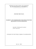
Figure 4. 1. Absorption spectrum and MB decomposition ability of TiO2 250oC combined irradiation
The absorption spectrum and the decomposition rate of MB over time using nano TiO2 powder
heated at 250°C are depicted in Figure 4.5. Similarly, when surveying for TiO 2 samples heated at different
temperatures from 250°C to 750°C, we provide a graph comparing the ability of MB color decomposition
and the number of MB molecules decompose over time in Figure 4.10.
hv
1.0
0.07
o
250 C
o
350 C
o
450 C
o
550 C
o
750 C
o
0.4
o
TiO2 450 C
o
TiO2 550 C
0.05
20
0.6
o
TiO2 250 C
TiO2 350 C
0.06
N.10
Nång ®é C/C0
0.8
hv
o
TiO2 750 C
0.04
0.03
0.02
0.2
0.01
0.0
-30
-20
-10
0
10
20
30
40
50
Thêi gian (phót)
60
0.00
-30 -20 -10 0
10 20 30 40 50 60 70 80 90 100
Thêi gian (phót)
Figure 4. 2. Comparison MB decomposition ability of TiO2 at different temperatures from 250oC to 750oC
From the results shown in Figure 4.11, nano-heated TiO2 below 350oC has an amorphous structure
with good MB decomposition but mainly adsorption. As the sample heating temperature increases, TiO2 has
anatase crystal phase structure from about 350oC to less than 650oC. With TiO2 with anatase structure, the
adsorption capacity decreases but absorption capacity increases. When the heating temperature reaches
750oC, in the presence of rutile phase, photocatalyst properties of TiO2 decrease.
4.3. PHOTOCATALYTIC APPLICATION OF RE DOPED NANO TiO2
In this section, we study photocatalytic properties of TiO2 doped 1% mol RE heat treated at 550oC
for 2 hours. Surveying similar to the previous section, we present a graph comparing the MB decomposition
22
ability and the number of MB molecules decaying over time under the impact of TiO 2 and TiO2 catalysts
doped with 1% mol Eu3+, TiO2 is doped with 1% mol of Sm3+ (Figure 4.14).
Figure 4. 3. Comparison diagram of MB decomposition ability of TiO2,
TiO2:Eu3+ (1% mol) and TiO2: Sm3+ (1% mol)
From the results presented in Figure 4.14, it shows that MB decomposition ability of TiO2 doped
3+
RE is better than pure TiO2. Due to doping of rare earth ions, the band gap of TiO2 decreases, thereby
increasing the ability to absorb light into the visible region. On the other hand, according to the results shown
in chapter 2, at the same sample heating temperature, RE-doped samples have lower anatase phase
crystallinity, and smaller particle size leads to smaller surface increase. Therefore, the photocatalytic
performance of RE3+ doped nano TiO2 material is higher than that of pure nano TiO2.
CONCLUSION
We have resolved the following issues:
- We presented material overview theory of nano TiO2 materials and nano TiO2 synthesis methods.
Overview of spectral characteristics of rare earth elements on the nano TiO2 host.
- We have devised a technological process and successfully fabricated nano-structure TiO2 by
hydrothermal method and method of using sulfuric acid. Nano TiO2 materials synthesized by ultrasonic hydrothermal method are nanorodic and spherical shaped for the method of using sulfuric acid with sizes
from several nm to several tens of nm. This is the first new point of the thesis.
- Study the effect of technological conditions such as annealing temperature and method of
fabricating materials on the structure and shape of manufactured materials. On the basis of manufactured
materials, we conducted a technological process for manufacturing nano TiO 2 doped with rare earth ions.
Since then, studying the effect of technological conditions, the concentration of doped rare earth ions on the
energy band structure, the size of TiO2 doped RE3+ (Eu3+, Sm3+). It is confirmed that rare earth ion doping
not only limits particle size growth but also prevents anatase crystal phase structure formation and rutile.
- Study the photoluminescence spectrum of TiO2 samples: Eu and TiO2:Sm3+ showed that the
luminescence of TiO2 samples: Eu and TiO2:Sm3+ emits narrow-line radiation typical for displacement of RE3+
ions in the lattice, they affected by technological conditions and concentration of doping.
- Explain the luminescence mechanism of rare earth centers (Eu3+, Sm3+) when doped into the nano
TiO2 host. Confirming the luminescence of Eu3+ ions in TiO2 sample: Eu3+ is formed mainly because Eu3+ ions
are located on the surface of TiO2 crystal particles. The radiation intensity increases when the concentration of
Eu3+ ions increases in the range of 1 - 15% mol. In contrast, the luminescence of Sm3+ ions in TiO2:Sm3+ is
mainly due to radiation of Sm3+ ions when they replace Ti4+ ions in TiO2:Sm3+ lattice. The maximum radiation
intensity with concentration Sm3+ ions is 1% mol and sharply decreases as the concentration increases. This is
the second new point of the thesis.
23
- Using Material Studio software to simulate the energy band structure of TiO2 with anarase and
rutile structure, TiO2 doped rare valence earth 3 (Eu3+, Sm3+) with crystal structure parameters was determined
from experiment. The results showed that, when doped with RE3+, the band gap of TiO2 sample decreased and
was suitable to the experiment. The photocatalyst capacity of Sm3+ doped TiO2 is better than that of Eu3+
doped TiO2 and better than the doped TiO2 sample. These are important results initially confirming the novelty
of the thesis (the third new point) towards the deployment of applications of nano TiO2 materials in the field of
environmental treatment.
Based on the results achieved, we propose the following
Study the optical properties of rare earth ions couple doped with nano TiO2 or use other impurity
ions as transition metal.
1.
2.
3.
4.
5.
PUBLISHED SCIENTIFIC ARTICLES RELATED TO THE THESIS
Nguyễn Trùng Dương, Nguyễn Mạnh Sơn, Trương Văn Chương (2016), “ Cấu trúc và vi cấu trúc
của TiO2 nano chế tạo bằng phương pháp axit Sulfuric”, Tạp chí khoa học-Đại học Huế, tập 117, số 3,
tr. 59-69.
Nguyen Trung Duong, Nguyen Manh Son, Le Đai Vuong, Ho Van Tuyen, Truong Van Chuong
(2017), “The synthesis of TiO2 nanoparticles using sulfuric acid method with the aid of ultrasound”,
Nanomaterials and Energy, Vol.6(2), pp.82-88.
Nguyen Trung Duong, Le Dai Vuong, Nguyen Manh Son, Dang Anh Tuan, Vo Thanh Tung, Ho Van
Tuyen, Truong Van Chuong (2018), “Photoluminescent Properties of Eu3+ Doped TiO2 Nanoparticles
Synthesized Using an Acid Sulfuric Method”, Wulfenia, Vol.25, No. 8, pp.137-146.
Nguyễn Trùng Dương, Nguyễn Mạnh Sơn, Nguyễn Trường Thọ, Nguyễn Văn Thịnh (2018) “Đặc
trưng quang phổ của TiO2 nano pha tạp Sm3+ tổng hợp bằng phương pháp siêu âm - thủy nhiệt”, Tạp chí
Khoa học và công nghệ trường Đại học Khoa học – Đại học Huế, tập 13, số 1, tr. 91-98.
Nguyễn Trùng Dương, Nguyễn Mạnh Sơn (2018) “Cơ chế phát quang của các ion đất hiếm Eu3+ và
Sm3+ trên nền TiO2 nano”, Tạp chí Khoa học Đại học Huế, tập 128, số 1A, tr. 27-38.
24