Analog Voltage Input
Bạn đang xem bản rút gọn của tài liệu. Xem và tải ngay bản đầy đủ của tài liệu tại đây (289.6 KB, 9 trang )
h t t p : / / r e s o u r c e . r e n e s a s . c o m Page 114
Chapter 9
Analog Voltage Input
Although parallel data described in the previous chapter are used for
inputting and outputting digital voltages, this chapter explains the A/D
converter used for inputting analog voltages. A/D conversion is used for
inputting from temperature sensors.
In this chapter, you should fully understand the methods for checking
and clearing the status flag (ADF) when A/D conversion has been completed or
in other cases since they are frequently used.
Note: The following is a negative logic signal:
9.1 A/D Converter Configuration
In a microcomputer-applied system, processing may require handling of
information input as analog voltages by an analog sensor (sensor which
generates analog voltages according to physical values such as temperature and
pressure). Since the microcomputer, however, is composed of digital circuits, it
is incapable of handling analog voltages as they are.
Analog voltages, therefore, must be converted into numeric data of several bits
before processing. This conversion from analog to digital is accomplished by
the A/D converter, which is a peripheral function designed to convert analog
voltages externally input into digital numeric data.
The H8/3048 A/D converter employs the successive comparison
method and has the following characteristics:
Input voltage range 0V to 5V (range of analog input voltages which can be converted into digital
numeric data.)
You can use desired voltages between 0V as the minimum and 0V to 5V as the
maximum.
You can obtain high-precision A/D conversion results, however, by setting the
maximum voltage as high as possible.
Resolution 10 bits (refers to how many bits of digital numeric data voltages are to be
converted into.)
10-bit resolution means that you can obtain conversion results in two to the
tenth power (1024) steps.
If you do not need so many steps, use the required bit count from the most
significant bit from the 10 bits. For example, you can obtain conversion results
h t t p : / / r e s o u r c e . r e n e s a s . c o m Page 115
in two to the eighth power (256) by using the upper 8 bits or to the fifth power
(32) by using the upper 5 bits.
Conversion time 266 or 134 states (time required for conversion.)
For 134-state conversion (shorter conversion time), one conversion takes 6.7
microseconds in the case of 20MHz operation. In this case, the sampling
measurement of signals having a period of
6.7 microseconds x 2 = 13.4 microseconds or longer (frequency of 75kHz or
lower)
is possible based on the sampling theorem.
Since the A/D converter is a circuit for handling analog electrical
signals, noise appears as conversion errors. If you want to suppress conversion
errors, take sufficient measures against them.
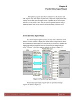
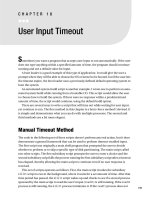
Figure 9.1: A/D Converter Block Diagram
The following explains the A/D converter configuration in the H8/3048.
It has 12 external input pins. AN0 to AN7 are designed to input analog
voltages to be A/D converted. These 8 input pins are switched to perform A/D
conversion one by one. AVcc is a power supply pin and AVss is a ground pin.
Since they are separated from other power supply or ground pins, the A/D
h t t p : / / r e s o u r c e . r e n e s a s . c o m Page 116
converter will not function unless power is supplied to them. If you want to
suppress conversion errors, sufficient measures are also required in this case,
too. V
REF
is a reference voltage pin for converting voltages between AVss and
V
REF
into 10 bits (1024 steps). A/D conversion is started after the trailing edge
has externally been input to the ADTRG pin. A/D conversion can also be
started by an instruction.
The analog voltage input in the selected analog input pin is converted
into 10-bit binary data using the successive comparison method and stored in
the AD data registers (ADDRA to ADDRD). There are four 16-bit A/D data
registers from A to D and conversion results are stored in one of them
depending on which analog input pin has been selected. The A/D conversion
results are read using the MOV instruction. The A/D converter has two more
registers for controlling other settings such as the operating mode, which are
described in the following section.
9.2 A/D Converter Registers
Table 9.1 shows the A/D converter register configuration.
Table 9.1: A/D Converter Register Configuration
Each register is described below.
(1) A/D control status register (ADCSR)
Figure 9.2 shows the A/D control status register (ADCSR), which
selects the channel to be A/D converted, instructs the start of A/D conversion
and judges its end.
h t t p : / / r e s o u r c e . r e n e s a s . c o m Page 117
Figure 9.2: A/D Control Status Register (ADCSR)
Although all 8 bits of this register are capable of reading, indicated by
"R" under each bit, certain conditions apply to one of them regarding writing,
indicated by "W" in parentheses with "*" attached. The bit marked "W" in
parentheses with "*" attached is generally called the "status flag", which
requires some precautions. The status flag bit also exists in other internal I/O
registers, to which common precautions apply. As for this flag, press the link
button shown above ("How to use the status flag") to completely master the use
before proceeding.
(2) A/D control register (ADCR)
Figure 9.3 shows the A/D control register (ADCR), which has only one
significant bit (bit 7). If this trigger enable bit (TRGE) is not changed from its
default value of 0, A/D conversion will not be started even if the trailing edge
is input to the ADTRG pin. In this case, conversion can be started by
instruction only (setting the ADST of the ADCSR to 1).
If the TRGE is set to 1, on the other hand, A/D conversion can be
started by inputting the trailing edge to the ADTRG pin. In this case, however,
A/D conversion can also be started by instruction.
h t t p : / / r e s o u r c e . r e n e s a s . c o m Page 118
Figure 9.3: A/D Control Register (ADCR)
Note: Do not set bit 0 of the ADCR to 1.
(3) A/D data registers A to D (ADDRA to ADDRD)
The 16-bit A/D data registers are designed to store A/D conversion
results and located at two consecutive addresses in the memory. Figure 9.4
shows the A/D data register A (ADDRA) as an example. Although the A/D
data registers B (ADDRB) to D (ADDRD) have different analog input pins and
addresses, the use is completely the same.
Although the ADDRA to ADDRD are 16-bit registers, conversion
results are stored in the upper 10 bits. To use only the upper 8 bits of the
conversion results, read them in byte-size units. To use all 10 bits of the
conversion results, read them in word-size units and handle them by shifting
them to the right by 6 bits or by other means.
Figure 9.4: A/D Data Register A (ADDRA)
9.3 Sample Use of A/D Converter
This section shows a program using an A/D converter, which is
assumed to operate under the following conditions:
• The AN0 analog voltage is A/D converted in single mode (results are
stored in the ADDRA).
• The conversion time is 134 states.
• The ADTRG pin is not used.
• The A/D conversion complete interrupt is not used.
• The main routine obtains A/D conversion results in 8-bit units to store
them in R1H and calls the OUTPUT subroutine.
Then, the above operation is repeated (the contents of the OUTPUT subroutine
are not shown).