Creating a GUI
Bạn đang xem bản rút gọn của tài liệu. Xem và tải ngay bản đầy đủ của tài liệu tại đây (300.42 KB, 28 trang )
2
Creating a GUI
Designing the GUI (p. 2-2) Designing the GUI before actually creating it in GUIDE.
Laying Out the GUI (p. 2-3) Using the GUIDE Layout Editor to arrange the GUI
components, such as push buttons, pop-up menus, and
axes.
Setting Properties for GUI
Components (p. 2-11)
Setting properties for each GUI component.
Programming the GUI (p. 2-17) Using the M-file editor to program the GUI.
Saving and Running a GUI (p. 2-26) Saving and running the GUI from the Layout Editor.
2
Creating a GUI
2-2
Designing the GUI
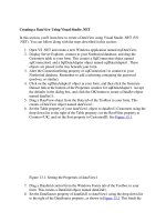
The GUI used in this example contains an axes that displays either a surface,
mesh, or contour plot of data selected from the pop-up menu. The following
picture shows a sketch that you might use as a starting point for the design.
A panel contains three push buttons that enable you to select the type of plot
you want. The pop-up menu contains three strings —
peaks
,
membrane
, and
sinc
, which correspond to MATLAB functions. You can select the data to plot
from this menu.
Select Data
peaks
Contour
Mesh
Surf
Axes
Push buttons to select
plot type
Menu for selecting
data
Plot Types
Panel to group push
buttons
Laying Out the GUI
2-3
Laying Out the GUI
This section illustrates how to lay out GUI components (i.e., a panel, axes, and
user interface controls, such as push buttons, pop-up menus, static text, etc.)
in the GUI. We recommend that you create the GUI for yourself, as this is the
best way to learn how to use GUIDE.
The section explains how to
• “View Layout and Code for the Example” on page 2-3
• “Open a New GUI in the Layout Editor” on page 2-4
• “Set the GUI Figure Size” on page 2-6
• “Add the Components” on page 2-7
• “Align the Components” on page 2-9
View Layout and Code for the Example
If you are reading this in the MATLAB Help browser, you can click the
following links to display the GUIDE Layout Editor and the MATLAB Editor
with a completed version of this example. This enables you to see the values of
all component properties and to understand how the components are
assembled to create the GUI. You can also see a complete listing of the code
that is discussed in the following sections.
Note The following links execute MATLAB commands and are designed to
work within the MATLAB Help browser.
• Layout Editor with completed GUI layout
• MATLAB Editor with completed M-file. The M-file contains the code that
controls the GUI.
An Animated Demo of Creating a GUI
The following link displays an animated version of this example.
Show GUIDE demonstration
2
Creating a GUI
2-4
Open a New GUI in the Layout Editor
Open GUIDE by typing
guide
at the MATLAB prompt. This displays the
Guide
Quick Start
dialog shown in the following figure.
If GUIDE is already open, you can display a similar dialog, by selecting
New
from the
File
menu. This dialog has no
Open Existing GUI
tab.
In the Quick Start dialog, select the
Blank GUI (default)
template. Click
OK
to display the blank GUI in the Layout Editor, as shown in the following figure.
Laying Out the GUI
2-5
To display the names of the GUI components in the component palette, select
Preferences
from the
File
menu, check the box next to
Show names in
component palette
, and click
OK
. The Layout Editor then appears as shown
in the following figure.
2
Creating a GUI
2-6
Set the GUI Figure Size
Specify the size of the GUI by resizing the grid area in the Layout Editor. Click
on the lower-right corner and resize the grid until it is about 4-by-3 inches.
If you want to set the position or size of the GUI to an exact value, do the
following:
1
Select
Property Inspector
from the
View
menu.
2
Select the button next to
Units
and then select
inches
from the pop-up
menu
3
Click the
+
sign next to
Position
.
4
Type the
x
and
y
coordinates of the point where you want the lower left
corner of the GUI to appear, and its width and height, as shown in the
following figure.
5
Reset the
Units
property to
characters
.
Click corner to resize
Laying Out the GUI
2-7
Note Setting the
Units
property to
characters
gives the GUI a more
consistent appearance across platforms.
Add the Components
1
Add the panel and push buttons to the GUI. Select the following components
from the component palette and drag them into the layout area:
- A panel
- Three push buttons
Select the panel and move it to where it appears in the original sketch. Resize
the panel to approximately 1-by-1.5 inches by selecting it with the mouse,
and then clicking and dragging the lower-left corner. Now, move the three
2
Creating a GUI
2-8
push buttons into the panel. As you move each push button into the panel,
GUIDE highlights the panel to indicate that the panel is the potential parent
of the push button. The following figure shows the highlight.
Note Panels, button groups, and figures can all be parents of component
objects and display this highlight when you move a component into them.
2
Add the remaining components to the GUI.
- A static text
- A pop-up menu
- An axes
Arrange the components as shown in the following figure. Resize the axes
component to approximately 2-by-2.
Laying Out the GUI
2-9
Align the Components
You can use the Alignment Tool to align components with respect to one
another if they have the same parent. For example, to align the three push
buttons:
1
Select all three push buttons by pressing
Ctrl
and clicking them.
2
Select
Align Objects
from the
Tools
menu to display the Alignment Tool.
3
Make the following settings in the Alignment Tool, as shown in the following
figure:
- 20 pixels spacing between push buttons in the vertical direction.
- Left-aligned in the horizontal direction.
4
Click
OK
.
2
Creating a GUI
2-10
Now align the tops of the axes and the panel. Note that when the panel moves,
its contents move with it.
To learn more about the Layout Editor, see “Using the Layout Editor” on
page 3-9
Setting Properties for GUI Components
2-11
Setting Properties for GUI Components
To set the properties of each GUI component, select the
Property Inspector
from the
View
menu to display the
Property Inspector
dialog box. When you
select a component in the Layout Editor, the Property Inspector displays that
component’s properties. If no component is selected, the Property Inspector
displays the properties of the GUI figure.
This section tells you how to set these properties:
• “Name Property” on page 2-11
• “Title Property” on page 2-12
• “String Property for Push Buttons and Static Text” on page 2-12
• “String Property for Pop-up Menus” on page 2-12
• “Callback Properties” on page 2-14
• “The Tag Property” on page 2-14
Name Property
The value of a figure’s
Name
property is the title that displays at the top of the
GUI.
The first time you save or run the GUI, GUIDE sets the value of
Name
to the
name of the FIG-file. Once the GUI is saved, you can set the value of
Name
to
the string you want to use as its title. In the field next to
Name
, type
Simple GUI
,
as shown in the following figure.