Lab 4.1.4 Creating a Network Map using CDP
Bạn đang xem bản rút gọn của tài liệu. Xem và tải ngay bản đầy đủ của tài liệu tại đây (168.29 KB, 4 trang )
1 - 4 CCNA 2: Routers and Routing Basics v 3.0 - Lab 4.1.4 Copyright 2003, Cisco Systems, Inc.
Lab 4.1.4 Creating a Network Map using CDP
Objective
• Use Cisco Discovery Protocol (CDP) commands to get information about neighboring network
devices.
Background/Preparation
CDP discovers and shows information about directly connected Cisco devices, including routers and
switches.
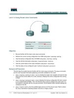
Cable a network similar to the one in the previous diagram. Any router that meets the interface
requirements may be used. Possible routers include 800, 1600, 1700, 2500, 2600 routers, or a
combination. Refer to the chart at the end of the lab to correctly identify the interface identifiers to be
used based on the equipment in the lab. The configuration output used in this lab is produced from
1721 series routers. Any other router used may produce slightly different output. The following steps
are intended to be executed on each router unless specifically instructed otherwise.
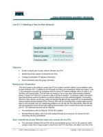
Start a HyperTerminal session as performed in the Establishing a HyperTerminal session lab.
Note: Go to the erase and reload instructions at the end of this lab. Perform those steps on all
routers in this lab assignment before continuing.
2 - 4 CCNA 2: Routers and Routing Basics v 3.0 - Lab 4.1.4 Copyright 2003, Cisco Systems, Inc.
Step 1 Log on to Router 1 (GAD)
a. Why is it necessary to log on to Router 1 in order to see all of the devices (routers and switches)
in the network shown above?
__________________________________________________________________________
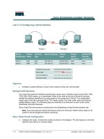
Step 2 Configured the routers
a. Configured the routers according to the information in the table above in order for CDP to be
able to collect information about them. Refer to prior labs on configuring serial and Ethernet
interfaces and making changes to configurations if you need help.
b. What is the clock rate to be set to and which interface is it set on?
__________________________________________________________________________
c. Why is it necessary to use the no shutdown command on all interfaces?
__________________________________________________________________________
Step 3 Gather information about the router interfaces
a. Enter show interface command at either the user EXEC or the privileged EXEC router
prompt.
b. How many interfaces are present?
____________________________________________
c. What type are they?
_______________________________________________________
Step 4 Display the CDP updates received on the local router
a. Enter show cdp neighbors command at the router prompt.
b. Fill in the following table:
Device and Port ID Local Interface Hold Time Capability Platform
Upon completion of the previous steps, logoff by typing exit. Turn the router off.
3 - 4 CCNA 2: Routers and Routing Basics v 3.0 - Lab 4.1.4 Copyright 2003, Cisco Systems, Inc.
Erasing and reloading the router
Enter into the privileged EXEC mode by typing enable.
If prompted for a password, enter class. If “class” does not work, ask the instructor for assistance.
Router>enable
At the privileged EXEC mode, enter the command erase startup-config.
Router#erase startup-config
The responding line prompt will be:
Erasing the nvram filesystem will remove all files! Continue?
[confirm]
Press Enter to confirm.
The response should be:
Erase of nvram: complete
Now at the privileged EXEC mode, enter the command reload.
Router(config)#reload
The responding line prompt will be:
System configuration has been modified. Save? [yes/no]:
Type n and then press Enter.
The responding line prompt will be:
Proceed with reload? [confirm]
Press Enter to confirm.
In the first line of the response will be:
Reload requested by console.
After the router has reloaded the line prompt will be:
Would you like to enter the initial configuration dialog? [yes/no]:
Type n and then press Enter.
The responding line prompt will be:
Press RETURN to get started!
Press Enter.
The router is ready for the assigned lab to be performed.
4 - 4 CCNA 2: Routers and Routing Basics v 3.0 - Lab 4.1.4 Copyright 2003, Cisco Systems, Inc.
Router Interface Summary
Router
Model
Ethernet
Interface #1
Ethernet
Interface #2
Serial
Interface #1
Serial
Interface #2
Interface
#5
800 (806) Ethernet 0 (E0) Ethernet 1 (E1)
1600 Ethernet 0 (E0) Ethernet 1 (E1) Serial 0 (S0) Serial 1 (S1)
1700 FastEthernet 0 (FA0) FastEthernet 1 (FA1) Serial 0 (S0) Serial 1 (S1)
2500 Ethernet 0 (E0) Ethernet 1 (E1) Serial 0 (S0) Serial 1 (S1)
2600 FastEthernet 0/0
(FA0/0)
FastEthernet 0/1 (FA0/1) Serial 0/0 (S0/0) Serial 0/1
(S0/1)
In order to find out exactly how the router is configured, look at the interfaces. This will identify the type of router
as well as how many interfaces the router has. There is no way to effectively list all of the combinations of
configurations for each router class. What is provided are the identifiers for the possible combinations of interfaces
in the device. This interface chart does not include any other type of interface even though a specific router may
contain one. An example of this might be an ISDN BRI interface. The string in parenthesis is the legal abbreviation
that can be used in IOS command to represent the interface.