Signaling System 7
Bạn đang xem bản rút gọn của tài liệu. Xem và tải ngay bản đầy đủ của tài liệu tại đây (500.39 KB, 26 trang )
Chapter 4. Signaling System 7
Signaling System 7 (SS7) is a common-channel signaling standard developed in the late 1970s by the
International Telecommunication Union Telecommunication Standardization Sector (ITU-T), formerly known as
the Consultative Committee for International Telegraph and Telephone (CCITT). SS7 was derived from SS6,
which was developed in the late 1960s and was the first generation of common-channel signaling. SS7 was
initially designed for telephony call-control applications. SS7 applications have greatly expanded since they
were first developed, however, and today's SS7 functionality includes database queries, transactions, network
operations, and Integrated Services Digital Network (ISDN).
SS7 is used to perform out-of-band signaling in the Public Switched Telephone Network (PSTN). SS7
signaling supports the PSTN by handling call establishment, exchange of information, routing, operations,
billing, and support for Intelligent Network (IN) services.
The SS7 protocol is important to Voice over IP (VoIP) and the way it inter-works with the PSTN. This inter-
working is critical to the acceptance and, ultimately, the success of VoIP solutions in today's telephone
network. Inter-working with a 100-year-old voice infrastructure is not a simple task, and it is naive to think that
this is an easy problem to solve. SS7 does provide a common protocol for signaling, messaging, and
interfacing for which you can develop VoIP-type devices, however.
SS7's objective was to provide a worldwide standard for telephony network signaling. This did not occur, and
many national variants were developed, such as the American National Standards Institute (ANSI) and Bell
Communications Research (Bellcore) standards used in North America as well as the European
Telecommunication Standards Institute (ETSI) standards used in Europe.
This chapter focuses on the ITU-T-defined standards for SS7 and covers the following aspects:
• SS7 Network Elements and Links
• SS7 Protocol Suite and Messages
• SS7 Examples and Call-flows
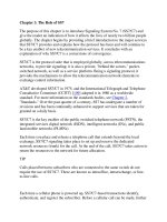
SS7 Network Architecture
The SS7 network is used to switch information messages to set up, manage, and release telephone calls as
well as to maintain the signaling network. SS7 network nodes are equipped with SS7 functionality and features
to become SS7 signaling points or elements. SS7 is a common-channel signaling network, in that all signaling
information is carried on a common signaling plane. The signaling planes and the voice circuit planes are
logically separated.
SS7 networks consist of three signaling elements—Service Switching Point (SSP), Signal Transfer Point
(STP), and Service Control Point (SCP)—and several link types, as illustrated in Figure 4-1
. This section
covers the signaling elements and signaling links in more detail.
64
Figure 4-1. SS7 Network Architecture
Signaling Elements
Signaling elements—which also are referred to as signaling points, endpoints, exchanges, switches, or
nodes— separate the voice network from the signaling network. All signaling elements are identified by a
numerical point code. Each signaling message contains the source and destination point code address.
Signaling elements use routing tables to route messages onto the appropriate path.
Signaling elements route signaling messages and provide access to the SS7 network and to databases.
Figure 4-2
shows the three types of signaling elements in the SS7 network.
Figure 4-2. Signaling Elements/Endpoints
• SSPs are end office or tandem switches that connect voice circuits and perform the necessary
signaling functions to originate and terminate calls.
• The STP routes all the signaling messages in the SS7 network.
• The SCP provides access to databases for additional routing information used in call processing. Also,
the SCP is the key element for delivering IN applications on the telephony network.
65
The following sections explore the three signaling elements of the SS7 network in more detail.
SSP
SSPs are telephone switches that are provisioned with SS7 capabilities. End office SSPs originate and
terminate calls, and core network switches provide tandem or transit calls. The SSP provides circuit-based
signaling messages to other SSPs for the purposes of connecting, disconnecting, and managing voice calls.
Non-circuit based messages are used to query databases when the dialed number is insufficient to complete
the call.
End office SSPs connect directly to users on their subscriber interfaces. The protocols used can vary from
analog to digital and can be based on ISDN Primary Rate Interface (PRI) or channel-associated switching
(CAS). The end office is in charge of translating subscriber protocol requests into SS7 messages to establish
calls.
The SSP uses the dialed number to complete the call, unless, for example, it is an 800, 888, 900, or Local
Number Portability exchange (or is ported NXX). In the latter case, a query is sent to an SCP requesting the
routing information (number) necessary to complete the call.
The following steps help explain the functions an SSP uses to complete a call. In this case, assume that the
originating and destination SSPs are directly attached, as illustrated in Figure 4-2:
1. The SSP uses the called number from the calling party or routing number from the database query to
begin circuit connection signaling messages.
2. Then the SSP uses its routing table to determine the trunk group and circuit needed to connect the
call.
3. At this point, a signaling setup message is sent to the destination SSP requesting a connection on the
circuit specified by the originating SSP.
4. The destination SSP responds with an acknowledgment granting permission to connect to the
specified trunk and proceeds to connect the call to the final destination.
STP
STPs, as illustrated in Figure 4-2
, are an integral part of the SS7 architecture providing access to the
network. STPs route or switch all the signaling messages in the network based on the routing information and
destination point code address contained in the message.
The STP provides the logical connectivity between SSPs without requiring direct SSP-to-SSP links. STPs are
configured in pairs and are mated to provide redundancy and higher availability. These mated STPs perform
identical functions and are considered the home STPs for the directly connected SSP or SCP. The STP also is
capable of performing global title translation, which is discussed later in this section.
Circuit-based messages are created on the SSP. Then, they are packetized in SS7 packets and sent from the
SSP. Usually they contain requests to connect or disconnect a call. These packets are forwarded to the
destination SSP where the call is terminated. It is the STP network's job to properly route such packets to the
destination.
Non-circuit based messages that originate from an SSP are database queries requesting additional
information needed to complete the call. These packets are forwarded to the destination SCP and are
addressed to the appropriate subsystem database. The SCP is the interface to the database that provides the
routing number required to complete the call.
STPs also measure traffic and usage. Traffic measurements provide statistics such as network events and
message types, and usage measurements provide statistics on the access and number of messages per
message type.
Global Title Translation
In addition to performing basic SS7 packet routing, STPs are capable of performing gateway services such as
global title translation. This function is used to centralize the SCP and database selection versus distributing all
66
possible destination selections to hundreds or thousands of distributed switches. If the SSP is unaware of the
destination SCP address, it can send the database query to its local STP. The STP then performs global title
translation and re-addresses the destination of the database query to the appropriate SCP.
Global title translation centralizes the selection of the correct database by enabling queries to be addressed
directly to the STP. SSPs, therefore, do not have the burden of maintaining every potential destination
database address. The term global title translation is taken from the term global title digits, which is another
term for dialed digits.
The STP looks at the global dialed digits and through its own translation table to resolve the following:
• The point code address of the appropriate SCP for the database
• The subsystem number of the database
The STP also can perform an intermediate global title translation by using its translation table to find another
STP. The intermediate STP then routes the message to the other STP to perform the final global title
translation.
STP Hierarchy
STP hierarchy defines network interconnection and separates capabilities into specific areas of functionality.
STP implementation can occur in multiple levels, such as:
• Local Signal Transfer Point
• Regional Signal Transfer Point
• National Signal Transfer Point
• International Signal Transfer Point
• Gateway Signal Transfer Point
The local, regional, and national STPs transfer standards-based SS7 messages within the same network.
These STPs usually are not capable of converting or handling messages in different formats or versions.
International STPs provide international connectivity where the same International Telecommunication Union
(ITU) standards are deployed in both networks.
Gateway STPs can provide the following:
• Protocol conversion from national versions to the ITU standard
• Network-to-network interconnection points
• Network security features such as screening, which is used to examine all incoming and outgoing
messages to ensure authorization
You can deploy and install STP functions on separate dedicated devices or incorporate them with other SSP
functions onto a single end office or tandem switch. Integrating SSP and STP functions is particularly common
in Europe and Australia. This is why fully associated SS7 or CCS7 (CCS7 is the ITU-T version of SS7)
networks are prevalent in those areas. Fully associated SS7 occurs when the same transmission channel
carries the bearer's information and the signaling information.
SCP
The SCP, as shown in Figure 4-2
, provides the interface to the database where additional routing information
is stored for non-circuit based messages. Service-provider SCPs do not house the required information; they
do, however, provide the interface to the system's database. The interface between the SCP and the database
system is accomplished by a standard protocol, which is typically X.25. The SCP provides the conversion
between the SS7 and the X.25 protocol. If X.25 is not the database access protocol, the SCP still provides the
capability for communication through the use of primitives.
The database stores information related to its application and is addressed by a subsystem number, which is
unique for each database. The subsystem number is known at the SSP level; the request originated within the
67
PSTN contains that identifier. The subsystem number identifies the database where the information is stored
and is used by the SCP to respond to the request.
The following databases are the most common in the SS7 network:
• 800 Database—Provides the routing information for special numbers, such as 800, 888, and 900
numbers. The 800 database responds to the special number queries with the corresponding routing
number. In the case of 800, 888, and 900 numbers, the routing number is the actual telephone number
at the terminating end.
• Line Information Database (LIDB)—Provides subscriber or user information such as screening and
barring, calling-card services including card validation and personal identification number (PIN)
authentication, and billing. The billing features of this database determine ways you can bill collect
calls, calling-card calls, and third-party services.
• Local Number Portability Database (LNPDB)—Provides the 10-digit Location Routing Number (LRN)
of the switch that serves the dialed-party number. The LRN is used to route the call through the
network, and the dialed-party number is used to complete the call at the terminating SSP.
• Home Location Register (HLR)—Used in cellular networks to store information such as current cellular
phone location, billing, and cellular subscriber information.
• Visitor Location Register (VLR)—Used in cellular networks to store information on subscribers roaming
outside the home network. The VLR uses this information to communicate to the HLR database to
identify the subscriber's location when roaming.
Signaling Links
All signaling points in the SS7 network are connected by signaling links. These full-duplex links simultaneously
transmit and receive SS7 messages over the network link. The signaling links are typically 56- and 64 kbps
data network facilities, either on standalone lines or extracted on channelized facilities such as structured E1
trunks.
This section covers the following topics:
• Signaling Modes
• Signaling Links and Linksets
• Signaling Routes
• Signaling Link Performance
Signaling Modes
The SS7 network has three modes of signaling:
• Associated Signaling
• Nonassociated Signaling
• Quasi-associated Signaling
Associated signaling, illustrated in Figure 4-3
, is the simplest form of signaling, in that the signaling and voice
paths are directly connected between the two signaling endpoints. This is not common in North America
because end office switches require direct connections to all other end office switches; however, associated
signaling is common in Europe, where the signaling path is actually derived within the E1 trunk facilities.
Figure 4-3. Associated Signaling
68
Nonassociated signaling uses a separate logical path for signaling and voice. As illustrated in Figure 4-4, the
signaling messages travel through multiple endpoints before reaching the final destination. Alternatively, the
voice path can have a direct path to the destination end office switch. Nonassociated signaling is the most
common form of signaling in the SS7 network.
Figure 4-4. Nonassociated Signaling
Quasi-associated signaling, shown in Figure 4-5
, uses a separate logical path for signaling through the
minimal number of transfer points to reach the final destination. The benefit of quasi-associated signaling is
that network delay is minimized due to the low number of transfer points between the origin and destination.
The quasi-associated method is more costly than the nonassociated method, however, because signaling links
need to be backhauled to a small number of STPs.
Figure 4-5. Quasi-Associated Signaling
Signaling Links and Linksets
The signaling links in the SS7 network are identified by the function provided to the corresponding endpoints,
as illustrated in Figure 4-6
.
69
Figure 4-6. Signaling Links
The following list outlines the six types of links present in the SS7 network:
• A-links are interconnects between signaling endpoints and STPs, as illustrated in Figure 4-6
. The
signaling endpoints are SSPs or SCPs, and each has at least two A-links that connect to the "home"
STP pair. It is possible to have only one A-link to an STP; however, this is not common practice.
These links provide access to the network for the purposes of transmitting and receiving signaling
messages. The STP routes the A-link signaling messages received from the originating SSP or SCP
toward the destination.
• Bridge Links (B-links) are interconnects between two mated pairs of STPs, as illustrated in Figure 4-
6. These mated STPs are peers operating at the same hierarchical level and are interconnected
through a quad of B-links. B-links carry signaling messages from the origin to the intended destination.
• Cross Links (C-links) interconnect an STP with its mate, as illustrated in Figure 4-6
. The STP pairs
perform identical functions and are mated to provide redundancy in the network. C-links are used only
when failure or congestion occurs, causing these links to become the only available path to the
network. Under normal conditions, these links carry only management traffic.
• Diagonal Links (D-links) are used to interconnect mated STP pairs of one hierarchical level to mated
STP pairs of another hierarchical level, as illustrated in Figure 4-7
. The D-links are connected in a
quad-like fashion similar to B-links. These links provide the same function as B-links; the distinction
between B- and D-links is arbitrary.
Figure 4-7. D-Links Interconnect Mated STPs on Different Hierarchical Levels
• Extended Links (E-links) are used to interconnect an SSP to an alternate STP, as illustrated in Figure
4-6. The SSP also is connected to the home STP pair through A-links; however, if more reliability is
70
required, you can implement E-links. This is not common practice, however, because the SSPs have
dual A-links to redundant mated STP pairs. These links are used only if failure or congestion occurs in
the home STPs.
• F-links are used to directly interconnect two signaling endpoints, as illustrated in Figure 4-6
. These
links are used when STPs are not available or when high traffic volumes exist. This is the only link
type whose signaling traffic is allowed to follow the same path as the voice circuits. The signaling
messages between the two signaling endpoints are associated only with the voice circuits directly
connected between the two signaling endpoints. This method is not commonly used in North America;
it is common in Europe, however.
Signaling links are grouped together into linksetswhen the links are connected to the same endpoint. Signaling
endpoints provide load sharing across all the links in a linkset. Combined linksets are used when connecting to
mated STP pairs with different point code addresses. In this case, links are assigned to different linksets and
are configured as a single combined linkset.
Load sharing across combined linksets occurs when signaling endpoints re-address the messages to adjacent
point codes. You can configure alternate linksets to provide redundant paths, increasing reliability over other
signaling links such as E- and F-links, as described later in this section.
Signaling Routes
Signaling endpoints have statically predefined routes for destination endpoints. The route is made up of
linksets; linksets can be part of more than one route. Groups of routes are called routesets and are defined in
routing tables to provide alternate routes when the current route is unavailable.
Signaling Link Performance
The availability of signaling in the SS7 network is critical to connect and serve telephone network users.
Signaling links provide signaling transmission and access to the SS7 network and, therefore, must be available
at all times. If congestion or failure occurs in the network, the links and STP pairs must handle the additional
traffic. The STP mated pairs and linkset configurations provide the necessary load sharing and redundancy
required to maintain SS7 network reliability.
SS7 Protocol Overview
The SS7 protocol stack and levels differ slightly from the Open Systems Interconnection (OSI) reference
model discussed in Chapter 7, "IP Tutorial."
A comparison between SS7 protocol levels and the layers of
the OSI model is illustrated in Figure 4-8
. As you can see, the SS7 protocol has only four levels, and the OSI
model has seven. SS7 Levels 1–3 (L1–L3) are identical to OSI L1–L3, and SS7 Level 4 (L4) corresponds to
OSI L4–Level 7 (L7).
71
Figure 4-8. SS7 Protocol Stack Versus the OSI Model
The following sections cover the suite of SS7 protocols identified in Figure 4-8
:
• Message Transfer Part (MTP) L1, L2, and L3 provide the transport protocols for all other SS7
protocols. MTP functionality includes network interface specifications, reliable transfer of information,
and message handling and routing.
• Signaling Connection Control Part (SCCP) provides end-to-end addressing and routing for L4
protocols such as transaction capabilities application part (TCAP).
• Telephone User Part (TUP) primarily is a link-by-link signaling system used to connect telephone or
speech calls as well as facsimile calls.
• ISDN User Part (ISUP) is a circuit-based protocol used to establish and maintain connections for voice
and data calls.
• TCAP provides access to remote databases for routing information and enables features in remote
network entities.
Physical Layer—MTP L1
The physical layer (L1) of the MTP defines the physical and electrical characteristics of the signaling link. Also
called MTP1, this SS7 protocol layer is virtually identical to OSI L1 and does not specify any particular
interface. The following list provides some examples of possible MTP1 network interfaces available in
networks today:
• T1—The standard in North America, Australia, Hong Kong, and Japan for digital transmission of voice,
data, and images. T1 (also known as DS1) signals transmit over two pairs of twisted wires with a
capacity of 1.544 Mbps. The T1 link has 24 full duplex channels or digital signal level 0s (DS-0s), each
consisting of 64 kbps. The payload yields a total of 1.536 Mbps, with the remaining 8 kbps used for
framing the T1 link.
• DS-0—The standard speed for digitizing one voice conversation using pulse code modulation (PCM).
Each of the 24 individual DS-0 channels is sampled at a rate of 8000 times per second, producing an
8-bit value (1 bit every 125 ms). The 24-channel, 8-bit values are multiplexed into a serial bit stream
using time-division multiplexing (TDM) to generate a 192-bit frame. One of the 8kbps framing bits is
added as the 193
rd
bit. The result is a T1 signal consisting of 8000 frames per second, whereby each
frame contains one framing bit and 24 channels of 8-bit samples.
• E1—The standard in South America, Europe, and Mexico for digital transmission of voice, data, and
images. E1 signals transmit over two pairs of twisted wire with a capacity of 2.048 Mbps. The E1 link
has 32 full duplex channels, each consisting of 64 kbps, which yields a total of 2.048 Mbps.
72
E1 is made up of 30 DS-0s (identical to the DS-0s found in T1) for voice and data, plus one channel
for signaling and one channel for framing.
• 56/64 kbps—The 56- and 64 kbps channels in T1 and E1 systems are DS-0s. The 56- and 64 kbps
interface rates are the most commonly used physical interfaces in the SS7 network.
• V.35—The ITU standard for interfacing between a digital service unit (DSU) and a packet/data device.
The V.35 interface has defined pin and electrical configurations for a 37-pin connector.
Data Layer—MTP L2
The data layer (L2) of the SS7 protocol is MTP L2, also called MTP2. The MTP2 protocol is used to create
reliable point-to-point links between endpoints in a network. MTP2 does not run across the network and,
therefore, is not concerned with the final destination of the message. MTP2 has the following mechanisms:
• Error Detection and Correction—Used to maintain data integrity during transmission. The error
detection mechanism in MTP2 is provided by cyclic redundancy check (CRC)-16. If CRC-16 detects
errors, MTP2 must request a retransmission.
• Sequencing of Packets—Used to identify lost messages during transmission. If lost messages are
detected, MTP2 must request a retransmission. Most protocols have a unique message structure to
indicate retransmissions. The message structure in SS7 enables the identification of retransmissions
in any message. Retransmission requests can be accompanied with the user data of the next
message. The user data in a retransmission message can be from another L4 application (that is,
SCCP, ISUP, TUP, or TCAP).
• Link Status Indicators—Used to maintain and monitor signaling links as well as monitor remote
processor outages.
The MTP2 protocol uses packets called signal units to transmit SS7 messages. The signal units are used in
the SS7 network to perform error detection, indicate link status, and transfer information messages. Three
types of signal units provide MTP2's data layer functions:
• Fill-in Signal Unit (FISU)—Provides link error detection in the SS7 network. As its name signifies, the
FISU packets fill in when no traffic is being sent on the network. This enables you to monitor the link at
all times, even when no traffic is on the network.
• Link Status Signal Unit (LSSU)—Provides link status on the link between two directly connected
signaling elements.
• Message Signal Unit (MSU)—Provides the structure to carry the information messages in the SS7
network. These information messages carry the payload for higher-level messages such as SCCP,
TUP, ISUP, and TCAP.
The following sections further discuss these signal units and the role they play in the SS7 network.
FISU
FISUs constantly are transmitted on the signaling links when the LSSU and MSUs are not present. FISUs are
sent only between signaling points and are not sent across the SS7 network. The FISU provides error-
detection capabilities to the signaling points at both ends of the link. This enables the signaling points to
perform error detection to verify link integrity and maintain reliability in the SS7 network.
If the signaling endpoints receive an FISU with errors, the signal unit is discarded. Retransmission of FISUs is
not required, as these signal units do not provide any L4 or user information. FISU fields are illustrated in
Figure 4-9
.
73