Working with Spatial Data
Bạn đang xem bản rút gọn của tài liệu. Xem và tải ngay bản đầy đủ của tài liệu tại đây (2.47 MB, 38 trang )
C H A P T E R 10
Working with Spatial Data
The addition of spatial capabilities was one of the most exciting new features introduced in SQL Server
2008. Although generally a novel concept for many SQL developers, the principles of working with
spatial data have been well established for many years. Dedicated geographic information systems
(GISs), such as ARC/INFO from ESRI, have existed since the 1970s. However, until recently, spatial data
analysis has been regarded as a distinct, niche subject area, and knowledge and usage of spatial data has
remained largely confined within its own realm rather than being integrated with mainstream
development.
The truth is that there is hardly any corporate database that does not store spatial information of
some sort or other. Customers’ addresses, sales regions, the area targeted by a local marketing
campaign, or the routes taken by delivery and logistics vehicles all represent spatial data that can be
found in many common applications.
In this chapter, I’ll first describe some of the fundamental principles involved in working with
spatial data, and then discuss some of the important features of the geometry and geography datatypes,
which are the specific datatypes used to represent and perform operations on spatial data in SQL Server.
After demonstrating how to use these methods to answer some common spatial questions, I’ll then
concentrate on the elements that need to be considered to create high-performance spatial applications.
Note Working with spatial data presents a unique set of challenges, and in many cases requires the adoption of
specific techniques and understanding compared to other traditional datatypes. If you’re interested in a more
thorough introduction to spatial data in SQL Server, I recommend reading Beginning Spatial with SQL Server 2008,
one of my previous books (Apress, 2008).
Modeling Spatial Data
Spatial data describes the position, shape, and orientation of objects in space. These objects might be
tangible, physical things, like an office building, railroad, or mountain, or they might be abstract features
such as the imaginary line marking the political boundary between countries or the area served by a
particular store.
SQL Server adopts a vector model of spatial data, in which every object is represented using one or
more geometries—primitive shapes that approximate the shape of the real-world object they represent.
There are three basic types of geometry that may be used with the geometry and geography datatypes:
Point, LineString, and Polygon:
283
CHAPTER 10 WORKING WITH SPATIAL DATA
• A Point is the most fundamental type of geometry, representing a singular
location in space. A Point geometry is zero-dimensional, meaning that it has no
associated area or length.
• A LineString is comprised of a series of two or more distinct points, together with
the line segments that connect those points together. LineStrings have a length,
but no associated area. A simple LineString is one in which the path drawn
between the points does not cross itself. A closed LineString is one that starts and
ends at the same point. A LineString that is both simple and closed is known as a
ring.
• A Polygon consists of an exterior ring, which defines the perimeter of the area of
space contained within the polygon. A polygon may also specify one or more
internal rings, which define areas of space contained within the external ring but
excluded from the Polygon. Internal rings can be thought of as “holes” cut out of
the Polygon. Polygons are two-dimensional—they have a length measured as the
total length of all defined rings, and also an area measured as the space contained
within the exterior ring (and not excluded by any interior rings).
Note The word geometry has two distinct meanings when dealing with spatial data in SQL Server. To make the
distinction clear, I will use the word geometry (regular font) as the generic name to describe Points, LineStrings,
and Polygons, and
geometry
(code font) to refer to the
geometry
datatype.
Sometimes, a single feature may be represented by more than one geometry, in which case it is
known as a GeometryCollection. GeometryCollections may be homogenous or heterogeneous. For
example, the Great Wall of China is not a single contiguous wall; rather, it is made up of several distinct
sections of wall. As such, it could be represented as a MultiLineString—a homogenous collection of
LineString geometries. Similarly, many countries, such as Japan, may be represented as a
MultiPolygon—a GeometryCollection consisting of several polygons, each one representing a distinct
island. It is also possible to have a heterogeneous GeometryCollection, such as a collection containing a
Point, three LineStrings, and two Polygons.
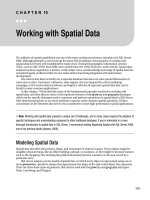
Figure 10-1 illustrates the three basic types of geometries used in SQL Server 2008 and some
examples of situations in which they are commonly used.
Having chosen an appropriate type of geometry to represent a given feature, we need some way of
relating each point in the geometry definition to the relevant real-world position it represents. For
example, to use a Polygon geometry to represent the US Department of Defense Pentagon building, we
need to specify that the five points that define the boundary of the Polygon geometry relate to the
location of the five corners of the building. So how do we do this?
You are probably familiar with the terms longitude and latitude, in which case you may be thinking
that it is simply a matter of listing the relevant latitude and longitude coordinates for each point in the
geometry. Unfortunately, it’s not quite that simple.
284
CHAPTER 10 WORKING WITH SPATIAL DATA
Figure 10-1. Different types of geometries and their common uses
What many people don’t realize is that any particular point on the earth’s surface does not have
only one unique latitude or longitude associated with it. There are, in fact, many different systems of
latitude and longitude, and the coordinates of a given point on the earth will vary depending on which
system is used. Furthermore, latitude and longitude coordinates are not the only way of expressing
positions on the earth—there are other types of coordinates that define the location of an object without
using latitude and longitude at all.
In order to understand how to specify the coordinates of a geometry, we first need to examine how
different spatial reference systems work.
285
CHAPTER 10 WORKING WITH SPATIAL DATA
Spatial Reference Systems
A spatial reference system is a system designed to unambiguously identify and describe the location of
any point in space. This ability is essential to enable spatial data to store the coordinates of geometries
used to represent features on the earth.
To describe the positions of points in space, every spatial reference system is based on an
underlying coordinate system. There are many different types of coordinate systems used in various
fields of mathematics, but when defining geospatial data in SQL Server 2008, you are most likely to use a
spatial reference system based on either a geographic coordinate system or a projected coordinate
system.
Geographic Coordinate Systems
In a geographic coordinate system, any position on the earth’s surface can be defined using two angular
coordinates:
• The latitude coordinate of a point measures the angle between the plane of the
equator and a line drawn perpendicular to the surface of the earth at that point.
• The longitude coordinate measures the angle in the equatorial plane between a
line drawn from the center of the earth to the point and a line drawn from the
center of the earth to the prime meridian.
Typically, geographic coordinates are measured in degrees. As such, latitude can vary between –90°
(at the South Pole) and +90° (at the North Pole). Longitude values extend from –180° to +180°.
Figure 10-2 illustrates how a geographic coordinate system can be used to identify a point on the
earth’s surface.
Projected Coordinate Systems
In contrast to the geographic coordinate system, which defines positions on a three-dimensional, round
model of the earth, a projected coordinate system describes positions on the earth’s surface on a flat,
two-dimensional plane (i.e., a projection of the earth’s surface). In simple terms, a projected coordinate
system describes positions on a map rather than positions on a globe.
If we consider all of the points on the earth’s surface to lie on a flat plane, we can define positions on
that plane using familiar Cartesian coordinates of x and y (sometimes referred to as Easting and
Northing), which represent the distance of a point from an origin along the x axis and y axis, respectively.
Figure 10-3 illustrates how the same point illustrated in Figure 10-2 could be defined using a projected
coordinate system.
286
CHAPTER 10 WORKING WITH SPATIAL DATA
Figure 10-2. Describing a position on the earth using a geographic coordinate system
Figure 10-3. Describing a position on the earth using a projected coordinate system
287
CHAPTER 10 WORKING WITH SPATIAL DATA
Applying Coordinate Systems to the Earth
A set of coordinates from either a geographic or projected coordinate system does not, on its own,
uniquely identify a position on the earth. We need to know additional information, such as where to
measure those coordinates from and in what units, and what shape to use to model the earth. Therefore,
in addition to specifying the coordinate system used, every spatial reference system must also contain a
datum, a prime meridian, and a unit of measurement.
Datum
A datum contains information about the size and shape of the earth. Specifically, it contains the details
of a reference ellipsoid and a reference frame, which are used to create a geodetic model of the earth
onto which a coordinate system can be applied.
The reference ellipsoid is a three-dimensional shape that is used as an approximation of the shape
of the earth. Although described as a reference ellipsoid, most models of the earth are actually an oblate
spheroid—a squashed sphere that can be exactly mathematically described by two parameters—the
length of the semimajor axis (which represents the radius of the earth at the equator) and the length of
the semiminor axis (the radius of the earth at the poles), as shown in Figure 10-4. The degree by which
the spheroid is squashed may be stated as a ratio of the semimajor axis to the difference between the two
axes, which is known as the inverse-flattening ratio.
Different reference ellipsoids provide different approximations of the shape of the earth, and there
is no single reference ellipsoid that provides a best fit across the whole surface of the globe. For this
reason, spatial applications that operate at a regional level tend to use a spatial reference system based
on whatever reference ellipsoid provides the best approximation of the earth’s surface for the area in
question. In Britain, for example, this is the Airy 1830 ellipsoid, which has a semimajor axis of
6,377,563m and a semiminor axis of 6,356,257m. In North America, the NAD83 ellipsoid is most
commonly used, which has a semimajor axis of 6,378,137m and a semiminor axis of 6,356,752m.
The reference frame defines a set of locations in the real world that are assigned known coordinates
relative to the reference ellipsoid. By establishing a set of points with known coordinates, these points
can then be used to correctly line up the coordinate system with the reference ellipsoid so that the
coordinates of other, unknown points can be determined. Reference points are normally places on the
earth’s surface itself, but they can also be assigned to the positions of satellites in stationary orbit around
the earth, which is how the WGS84 datum used by global positioning system (GPS) units is realized.
Prime Meridian
As defined earlier, the geographic coordinate of longitude is the angle in the equatorial plane between
the line drawn from the center of the earth to a point and the line drawn from the center of the earth to
the prime meridian. Therefore, any spatial reference system must state its prime meridian—the axis
from which the angle of longitude is measured.
It is a common misconception to believe that there is a single prime meridian based on some
inherent fundamental property of the earth. In fact, the prime meridian of any spatial reference system
is arbitrarily chosen simply to provide a line of zero longitude from which all other coordinates of
longitude can be measured. One commonly used prime meridian passes through Greenwich, London,
but there are many others. If you were to choose a different prime meridian, the value of every longitude
coordinate in a given spatial reference system would change.
288
CHAPTER 10 WORKING WITH SPATIAL DATA
Figure 10-4. Properties of a reference ellipsoid
Projection
A projected coordinate reference system allows you to describe positions on the earth on a flat, two-
dimensional image of the world, created as a result of projection. There are many ways of creating such
map projections, and each one results in a different image of the world. Some common map projections
include Mercator, Bonne, and equirectangular projections, but there are many more.
It is very important to realize that, in order to represent a three-dimensional model of the earth on a
flat plane, every map projection distorts the features of the earth in some way. Some projections attempt
to preserve the relative area of features, but in doing so distort their shape. Other projections preserve
the properties of features that are close to the equator, but grossly distort features toward the poles.
Some compromise projections attempt to balance distortion in order to create a map in which no one
289
CHAPTER 10 WORKING WITH SPATIAL DATA
aspect is distorted too significantly. The magnitude of distortion of features portrayed on the map is
normally related to the extent of the area projected. For this reason, projected spatial reference systems
tend to work best when only applied to a single country or smaller area, rather than a full world view.
Since the method of projection affects the features on the resulting map image, coordinates from a
projected coordinate system are only valid for a given projection.
Spatial Reference Identifiers
The most common spatial reference system in global usage uses a geographic coordinate based on the
WGS84 datum, which has a reference ellipsoid of radius 6,378,137m and an inverse-flattening ratio of
298.257223563. Coordinates are measured in degrees, based on a prime meridian of Greenwich. This
system is used by handheld GPS devices, as well as many consumer mapping products, including Google
Earth and Bing Maps APIs.
Using the Well-Known Text (WKT) format, which is the industry standard for such information (and
the system SQL Server uses in the well_known_text column of the sys.spatial_references table), the
properties of this spatial reference system can be expressed as follows:
GEOGCS[
"WGS 84",
DATUM[
"World Geodetic System 1984",
ELLIPSOID[
"WGS 84",
6378137,
298.257223563
]
],
PRIMEM["Greenwich", 0],
UNIT["Degree", 0.0174532925199433]
]
Returning to the example at the beginning of this chapter, using this spatial reference system, we
can describe the approximate location of each corner of the US Pentagon building as a pair of latitude
and longitude coordinates as follows:
38.870, -77.058
38.869, -77.055
38.871, -77.053
38.873, -77.055
38.872, -77.058
Note that, since we are describing points that lie to the west of the prime meridian, the longitude
coordinate in each case is negative.
Now let’s consider another spatial reference system—the Universal Transverse Mercator (UTM)
Zone 18N system, which is a projected coordinate system used in parts of North America. This spatial
reference system is based on the 1983 North American datum, which has a reference ellipsoid of
6,378,137m and an inverse-flattening ratio of 298.257222101. This geodetic model is projected using a
transverse Mercator projection, centered on the meridian of longitude 75°W, and coordinates based on
the projected image are measured in meters. The full properties of this system are expressed in WKT
format as follows:
290
CHAPTER 10 WORKING WITH SPATIAL DATA
PROJCS[
"NAD_1983_UTM_Zone_18N",
GEOGCS[
"GCS_North_American_1983",
DATUM[
"D_North_American_1983",
SPHEROID[
"GRS_1980",
6378137,
298.257222101
]
],
PRIMEM["Greenwich",0],
UNIT["Degree", 0.0174532925199433]
],
PROJECTION["Transverse_Mercator"],
PARAMETER["False_Easting", 500000.0],
PARAMETER["False_Northing", 0.0],
PARAMETER["Central_Meridian", -75.0],
PARAMETER["Scale_Factor", 0.9996],
PARAMETER["Latitude_of_Origin", 0.0],
UNIT["Meter", 1.0]
]
Using this spatial reference system, the same five points of the Pentagon building can instead be
described using the following coordinates:
321460, 4304363
321718, 4304246
321896, 4304464
321728, 4304690
321465, 4304585
Comparing these results clearly demonstrates that any coordinate pair only describes a unique
location on the earth when stated with the details of the coordinate system from which they were
obtained. However, it would be quite cumbersome if we had to write out the full details of the datum,
prime meridian, unit of measurement, and projection details every time we wanted to quote a pair of
coordinates. Fortunately, there is an established set of spatial reference identifiers (SRIDs) that provide
a unique integer code associated with each spatial reference system. The two spatial reference systems
used in the preceding examples are represented by SRID 4326 and SRID 26918, respectively.
Every time you state an item of spatial data using the geography or geometry types in SQL Server
2008, you must state the corresponding SRID from which the coordinate values were obtained. What’s
more, since SQL Server does not provide any mechanism for converting between spatial reference
systems, if you want to perform any calculations involving two or more items of spatial data, each one
must be defined using the same SRID.
If you don’t know the SRID associated with a set of coordinates—say, you looked up some latitude
and longitude coordinates from a web site that didn’t state the system used—the chances are more than
likely that they are geographic coordinates based on SRID 4326, the system used by GPSs.
291
CHAPTER 10 WORKING WITH SPATIAL DATA
Note To find out the SRID associated with any given spatial reference system, you can use the search facility
provided at
www.epsg-registry.org
.
Geography vs. Geometry
Early Microsoft promotional material for SQL Server 2008 introduced the geography datatype as suitable
for “round-earth” data, whereas the geometry datatype was for “flat-earth” data. These terms have since
been repeated verbatim by a number of commentators, with little regard for explaining the practical
meaning of “flat” or “round.” A simple analogy might be that, in terms of geospatial data, the geometry
datatype operates on a map, whereas the geography datatype operates on a globe.
With that distinction in mind, one obvious difference between the datatypes concerns the types of
coordinates that can be used with each:
• The geography datatype requires data to be expressed using latitude and longitude
coordinates, obtained from a geographic coordinate system. Furthermore, since
SQL Server needs to know the parameters of the ellipsoidal model onto which
those coordinates should be applied, all geography data must be based on one of
the spatial reference systems listed in the sys.spatial_reference_systems system
table.
• The geometry datatype operates on a flat plane, which makes it ideal for dealing
with geospatial data from projected coordinate systems, including Universal
Transverse Mercator (UTM) grid coordinates, national grid coordinates, or state
plane coordinates. However, there are occasions when you may wish to store
latitude and longitude coordinates using the geometry datatype, as I’ll
demonstrate later this chapter. The geometry datatype can also be used to store
any abstract nonspatial data that can be modeled as a pair of floating point x, y
coordinates, such as the nodes of a graph.
This distinction between coordinate types is not the only property that distinguishes the two
datatypes. In the following sections I’ll analyze some of the other differences in more detail.
Note Both the flat plane used by the
geometry
datatype and the curved ellipsoidal surface of the
geography
datatype are two-dimensional surfaces, and a position on those surfaces can be described using exactly two
coordinates (latitude and longitude for the
geography
datatype, or x and y for the
geometry
datatype). SQL Server
2008 also allows you to store
Z
and
M
coordinates, which can represent two further dimensions associated with
each point (typically,
Z
is elevation above the surface, and
M
is a measure of time). However, while these values
can be stored and retrieved, none of the methods provided by the
geography
or
geometry
datatypes account for
the value of
Z
and
M
coordinates in their calculations.
292
CHAPTER 10 WORKING WITH SPATIAL DATA
Standards Compliance
The geometry datatype operates on a flat plane, where the two coordinate values for each point represent
the x and y position from a designated origin on the plane. As a result, many of the standard methods
provided by the geometry datatype can be performed using elementary trigonometry and geometry. For
example, the following code listing demonstrates how to calculate the distance between a Point located
at (50,100) and a Point at (90,130) using the STDistance() method of the geometry datatype:
DECLARE @point1 geometry = geometry::Point(50, 100, 0);
DECLARE @point2 geometry = geometry::Point(90, 130, 0);
SELECT @point1.STDistance(@point2);
The result, 50, could have been obtained without using the geometry datatype, using basic knowledge of
the Pythagorean theorem, as in the following equivalent T-SQL query:
DECLARE
@x1 int = 50, @y1 int = 100,
@x2 int = 90, @y2 int = 130;
SELECT
SQRT(
POWER(@x2 - @x1, 2) +
POWER(@y2 - @y1, 2)
);
Of course, other geometry operations, such as finding whether a Point lies within a Polygon, or the
area created by the intersection of two Polygons, become more involved than the simple example given
here, but they are still generally achievable using alternative methods in T-SQL or SQLCLR. So why the
fuss about the geometry datatype?
One key benefit of implementing such functionality using the geometry datatype instead of rolling
your own code is that all the methods implemented by the geometry datatype conform to the Open
Geospatial Consortium (OGC) Simple Features for SQL Specification v1.1.0. This is the industry standard
format for the interchange and implementation of spatial functionality. By using the geometry datatype,
you can be sure that the results of any spatial methods will be the same as those obtained from any other
system based on the same standards.
Note that although OGC compliance ensures consistency of results, the OGC methods do not
necessarily give predictable results, at least not in the sense that you can reasonably guess the behavior
of a method based on its name alone. For example, consider the two LineStrings illustrated in Figure
10-5.
Figure 10-5. Two LineStrings that cross but do not touch
293
CHAPTER 10 WORKING WITH SPATIAL DATA
In normal English language, most people would describe these two LineStrings as touching, but not
crossing. However, according to the OGC definitions, the reverse is true. You can test this for yourself by
examining the results of the STTouches() and STCrosses() methods, as shown in the following code
listing:
DECLARE @x geometry = geometry::STLineFromText('LINESTRING(0 0, 0 10)', 0);
DECLARE @y geometry = geometry::STLineFromText('LINESTRING(10 0, 0 5, 10 10)', 0);
SELECT
@x.STCrosses(@y),
@x.STTouches(@y);
The result of the STCrosses() method is 1, indicating that the LineString x crosses over the
LineString y. According to the OGC standards, two LineStrings cross each other if the geometry created
by their intersection is zero-dimensional. In this case, the two LineStrings intersect at a single point (5,5),
so they are deemed to cross. In contrast, two LineStrings only touch each other if the points at which
they intersect lie in the boundary (i.e., the ends) of the LineString. In this case, the point (5,5) lies in the
interior of both LineStrings rather than in their boundary, so the result of STTouches() is 0 (i.e., false). Be
careful to check the documentation of any methods to ensure that the behavior is exactly as you expect!
Accuracy
The world is round. The geometry datatype, however, operates on a flat plane. By definition, therefore,
any geospatial calculations performed using the geometry datatype will involve a degree of error. This is
not a limitation of the geometry datatype in itself, but rather of the inevitable distortions introduced
when using a projected coordinate system to represent a round model of the earth.
Generally speaking, the effects of distortion become greater as the area of projection is increased.
For this reason, results obtained using the geometry datatype will become less accurate than results
obtained using the geography datatype over large distances.
In global spatial applications, the geography datatype is a more suitable choice, as there are few
projected systems that can be used for general global purposes with sufficient accuracy. For storing
spatial data contained within a single country or smaller area, the geometry datatype will generally
provide sufficient accuracy, and comes with the benefits of additional functionality over the geography
type.
Technical Limitations and Performance
The ellipsoidal calculations used by the geography datatype are by their nature more complex than the
planar calculations of the geometry datatype. This means that applications using the geography datatype
may experience slightly slower performance than those based on the geometry datatype, although the
impact is not normally significant. Additionally, the indexes created on columns of geometry data may
specify an explicit bounding box, creating a more granular grid, which leads to more efficient filtering of
results than a geography index, which is assumed to span the entire globe (but more on that later).
However, there are other more important implications arising between the different models on
which the two datatypes are based. The first of these differences is that currently, no geography instance
may exceed a single hemisphere. In this context, the term hemisphere means one-half of the surface of
the earth, centered about any point on the globe. Thus, it is not possible to have a geography MultiPoint
instance containing one Point at the North Pole and one at the South Pole. Nor is it possible to have a
geography LineString that extends from London to Auckland and then on to Los Angeles. In order to
work around this limitation, you must break down large geography objects into several smaller objects
294
CHAPTER 10 WORKING WITH SPATIAL DATA
that each fit within a hemisphere. In contrast, there is no limit to the size of a geometry instance, which
may extend indefinitely on an infinite plane.
The second technical difference arises from the conceptual differences of working on a curved
surface rather than a flat plane. As defined earlier, the external ring of a Polygon defines an area of space
contained within the Polygon, and may also contain one or more internal rings that define “holes”—
areas of space cut out from the Polygon. This is fairly straightforward to visualize when drawing
Polygons on a flat piece of paper. However, a problem occurs when you try to apply this definition on a
continuous round surface such as used by the geography datatype, because it becomes ambiguous as to
which area of space is contained inside a Polygon ring, and which is outside.
To demonstrate this problem, consider Figure 10-6, which illustrates a Polygon whose exterior ring
is a set of points drawn around the equator. Does the area contained within the Polygon represent the
Northern Hemisphere or the Southern Hemisphere?
Figure 10-6. Polygon ring orientation is significant for the geography datatype
The solution used by SQL Server (and in common with some other spatial systems) is to consider
the ring orientation of the Polygon—i.e., the order in which the points of the ring are specified. When
defining a geography Polygon, SQL Server treats the area on the “left” of the path drawn between the
points as contained within the ring, whereas the points on the “right” side are excluded. Thus, the
Polygon depicted in Figure 10-6 represents the Northern Hemisphere. Whenever you define geography
polygons, you must ensure that you specify the correct ring orientation or else your polygons will be
“inside-out”—excluding the area they were intended to contain, and including everything else. In
geometry, data ring orientation is not significant, as there is no ambiguity as to the area contained within
a Polygon ring on a flat plane.
295
CHAPTER 10 WORKING WITH SPATIAL DATA
A final technical difference concerns invalid geometries. In an ideal world, we would always want
our spatial data to be “valid”—that is, it meeting all the OGC specifications for that type of geometry.
However, as developers we have to reluctantly accept that spatial data, like any other data, is rarely as
perfect as we would like. This means that you will frequently encounter invalid data where, for example,
Polygons do self-intersect.
Rather perversely, perhaps, the geometry datatype, which conforms to OGC standards, is also the
datatype that provides options for dealing with data that fails to meet those standards. For example, not
only can the geometry datatype be used to store invalid geometries, but it also provides the STIsValid()
method to identify whether a geometry is valid or not, and the MakeValid() method to attempt to “fix”
invalid geometries. All geography data, in contrast, is assumed to be valid at all times. Although this
means that once geography data is in SQL Server, you can work with it comfortable in the knowledge
that it is always valid, it can provide an obstacle to importing that data in the first place. Since SQL Server
cannot import invalid geography data, you may have to rely on external tools to validate and fix any
erroneous data prior to importing it.
Creating Spatial Data
The first challenge presented to many users new to the spatial features in SQL Server 2008 is how to get
spatial data into the database. Unfortunately, the most commonly used spatial format, the ESRI
shapefile format (SHP), is not directly supported by any of the geography or geometry methods, nor by
any of the file data sources available in SQL Server Integration Services (SSIS). What’s more, internally,
geography and geometry data is stored using a proprietary binary format, which is quite complex. For
readers who are interested, the structure is documented at />us/library/ee320529.aspx, but in general you do not need to worry about the specifics involved, as SQL
Server instead provides static methods to create spatial data from three different alternative spatial
formats: WKT, Well-Known Binary (WKB), and Geography Markup Language (GML).
Well-Known Text
WKT is a simple, text-based format defined by the OGC for the exchange of spatial information. Owing to
its easy readability and relative conciseness, the WKT format is a popular way of storing and sharing
spatial data, and is the format used in most of the examples in this chapter. It is also the format used in
the spatial documentation in SQL Server 2008 Books Online, at
/>us/library/ms130214.aspx
.
The following code listing demonstrates the WKT string used to represent a Point geometry located
at an x coordinate of 258647 and a y coordinate of 665289:
POINT(258647 665289)
Based on the National Grid of Great Britain, which is a projected coordinate system denoted by the
SRID 27700, these coordinates represent the location of Glasgow, Scotland. Once we know the WKT
string and the relevant SRID, we can create a geometry Point instance representing the city using the
STPointFromText method as follows:
DECLARE @Glasgow geometry;
SET @Glasgow = geometry::STPointFromText('POINT(258647 665289)', 27700);
GO
296
CHAPTER 10 WORKING WITH SPATIAL DATA
In order to create more complex geometries from WKT, simply specify the individual coordinate
pairs of each point in a comma-delimited list, as shown in the following example, which creates a
LineString between two points representing Sydney Harbor Bridge:
DECLARE @SydneyHarbourBridge geography;
SET @SydneyHarbourBridge = geography::STLineFromText(
'LINESTRING(151.209 -33.855, 151.212 -33.850)', 4326);
GO
Note that when using WKT to express coordinates for use in the geography datatype, as in the last
example, the longitude coordinate must be listed first in each coordinate pair, followed by the latitude
coordinate. This is in contrast to the expression of a “latitude, longitude” coordinate pair, which most
people are familiar with using in everyday speech.
One disadvantage of the WKT format is that, as with any text-based representation, it is not possible
to precisely state the value of certain floating-point coordinate values obtained from binary methods.
The inevitable rounding errors introduced when attempting to do so will lead to a loss of precision.
Additionally, since SQL Server must parse the text in a WKT representation to create the relevant spatial
object, instantiating objects from WKT can be slower than when using other methods.
Well-Known Binary
The WKB format, like the WKT format, is a standardized way of representing spatial data defined by the
OGC. In contrast to the text-based WKT format, WKB represents a geometry or geography object as a
contiguous stream of bytes in binary format. Every WKB representation begins with a header section
that specifies the order in which the bytes are listed (big-endian or little-endian), a value defining the
type of geometry being represented, and a stream of 8-byte values representing the coordinates of each
point in the geometry.
The following code demonstrates how to construct a Point geometry from WKB representing the
city of Warsaw, Poland, located at latitude 52.23 and longitude 21.02, using the geography
STPointFromWKB() method:
DECLARE @Warsaw geography;
SET @Warsaw = geography::STPointFromWKB(
0x010100000085EB51B81E0535403D0AD7A3701D4A40,
4326);
One advantage of using WKB is that it can be more efficiently processed than either of the text-
based (GML or WKT) formats. Additionally, since it is a binary format, WKB maintains the precision of
floating-point coordinate values calculated from binary operations, without the rounding errors
introduced in a text-based format. It is therefore the best choice of format for transmission of spatial
data directly between system interfaces, where the speed and precision of this format are beneficial and
the lack of human readability is not significant.
Note Although SQL Server stores spatial data in a binary format similar to WKB, it is not the same. In order to
create items of spatial data from WKB, you must supply it to the appropriate
STxxxxFromWKB()
method.
297