Górecki 2016 j phys conf ser 709 012010
Bạn đang xem bản rút gọn của tài liệu. Xem và tải ngay bản đầy đủ của tài liệu tại đây (1.27 MB, 8 trang )
Journal of Physics: Conference Series
Related content
PAPER • OPEN ACCESS
The influence of core material on transient thermal
impedances in transformers
To cite this article: K Górecki and K Górski 2016 J. Phys.: Conf. Ser. 709 012010
View the article online for updates and enhancements.
- A System for Cooling Electronic Elements
with an EHD Coolant Flow
M Tanski, M Kocik, R Barbucha et al.
- Transient thermal characteristics of hightemperature SiC power module enhanced
with Al-bump technology
Hidekazu Tanisawa, Fumiki Kato, Kenichi
Koui et al.
- Switching performance of power
MOSFETs with capacitive loads at high
frequency and high voltage for square
wave generators
P H Chappell and K J Campden
Recent citations
- Influence of Packaging Processes and
Temperature on Characteristics of
Schottky Diodes Made of SiC
Pawel Gorecki et al
- Krzysztof Gorecki and Krzysztof Gorski
- Krzysztof Gorecki and Krzysztof Gorski
This content was downloaded from IP address 117.1.178.183 on 06/07/2020 at 18:29
MicroTherm’2015 and SENM’2015
Journal of Physics: Conference Series 709 (2016) 012010
IOP Publishing
doi:10.1088/1742-6596/709/1/012010
The influence of core material on transient thermal
impedances in transformers
K Górecki and K Górski
Gdynia Maritime University, Department of Marine Electronics, Morska 83, Gdynia,
Poland
E-mail:
Abstract. In the paper the results of measurements of thermal parameters of impulsetransformers containing cores made of different ferromagnetic materials are presented.
Investigations were performed with the use of methods worked out in Gdynia Maritime
University. The obtained results of measurements prove that the material of the core does not
influence transient thermal impedance of the winding, whereas this parameter visibly changes
with the change of spatial orientation of the transformer. In turn, the material of the core
decides about transient thermal impedance of the core. Additionally, the influence of the core
material on temperature distribution on the surface of the transformer was analysed.
1. Introduction
Impulse-transformers are commonly used in switch-mode power supplies [1, 2, 3]. The considered
elements have a simple construction - they consist of the ferromagnetic core and windings. The
properties of both these components depend on temperature, whose change causes changes in the
value of exploitive parameters of the core and windings [4, 5, 6]. Particularly, if the core temperature
is higher than the Curie temperature, permeability of this core decreases to 1, and when the windings
temperature is higher than its admissible value, isolation of wires can be destructed [1, 2].
The temperature of the core and windings of the transformer during its operation is higher than the
ambient temperature due to self-heating phenomena in the core and in the windings, as well as the
mutual thermal coupling between these components of the transformer [4, 7, 8, 9]. In the papers [4, 8,
9] compact thermal models of the transformer are proposed. These models use the idea of the
transformer’s own and mutual transient thermal impedances well-known from models of
semiconductor devices [10, 11, 12]. As it is known from some papers, e.g. [11, 13], thermal
parameters of semiconductor devices depend on such factors as dissipated power, dimensions of the
considered devices and construction of the cooling system. Therefore, it can be expected that thermal
parameters of transformers depend on their dimensions and parameters of materials used to produce
ferromagnetic cores. Magnetic materials are characterized by different values of thermal conductance,
which should influence transient thermal impedance of the transformer.
In the paper the results of measurements of transformers’ own and mutual transient thermal
impedances, obtained with the use of the measurement method elaborated at Gdynia Maritime
University [14], are presented. These transformers contain cores made of different materials.
Additionally, inequalities of temperature distribution on the surface of the investigated elements are
discussed.
Content from this work may be used under the terms of the Creative Commons Attribution 3.0 licence. Any further distribution
of this work must maintain attribution to the author(s) and the title of the work, journal citation and DOI.
Published under licence by IOP Publishing Ltd
1
MicroTherm’2015 and SENM’2015
Journal of Physics: Conference Series 709 (2016) 012010
IOP Publishing
doi:10.1088/1742-6596/709/1/012010
2. Measurement methods
In the research the method of measurements of the transformer’s own and mutual transient thermal
impedances described in the paper [14] is used. This method is realised in the measurement set
presented in Figure 1.
Figure 1. The measurement set to measure thermal parameters of transformers [14]
The measurements are conducted in two steps. The first step needs stimulations of the primary
winding with a jump of the current and the measurement of temperature changes of windings and of
the core by means of the thermo-hunter until the thermally steady-state is obtained. These
measurements are used to calculate transient thermal impedance of the winding ZthU(t) and mutual
transient thermal impedance between the core and the windings ZthUR(t) using the following formulas:
TU (t ) − Ta
P
T (t ) − Ta
Z thUR (t ) = R
P
Z thU (t ) =
(1)
(2)
where TU(t) and TR(t) denote waveforms of the winding and core temperatures, respectively, Ta is the
ambient temperature, whereas P denotes power dissipated in the winding, which is equal to the
product of the winding current and the voltage on the primary winding.
In the second step, the primary winding of the transformer is stimulated by a sinusoidal signal of
frequency f and the temperature of the core is measured by the thermo-hunter. When the steady state is
obtained, in the moment t = 0 the power supply of the primary winding is switched off and waveforms
of temperature of the core and windings are measured. On the basis of the area SH of the obtained
hysteresis loop B(H) of the core and the measured waveform of the core temperature, transient thermal
impedance of the core ZthR(t) is calculated using the following formula
Z thR (t ) =
TR (t = 0 ) − TR (t )
VR ⋅ f ⋅ S H
(3)
where VR represents the volume of the core.
The detailed description of the method is included in [14].
3. Measurement results
Using the method presented in section 2, the measurements of thermal parameters of transformers
containing toroidal cores of the diameter equal to about 26 mm are performed. The core made of
powdered iron (RTP), the ferrite core (RTF) and the nanocrystaline core (RTN) are applied. Each of
the considered transformers has two windings made of 30 turns of copper wire in enamel of the
diameter equal to 0.8 mm.
In the further part of this section the results of measurements illustrating the influence of core
material and spatial orientation of the transformer on the courses of transient thermal impedances
ZthU(t), ZthR(t) and ZthUR(t) are presented. The spectrum of transient thermal impedances for all the
considered cooling conditions and selected temperature distributions on the surface of the investigated
transformers are also shown. All the measurements are performed at the constant ambient temperature
equal to 22°C. In all the figures presented in this section, solid lines correspond to the transformer
2
MicroTherm’2015 and SENM’2015
Journal of Physics: Conference Series 709 (2016) 012010
IOP Publishing
doi:10.1088/1742-6596/709/1/012010
situated horizontally, and dashed lines - the transformer situated vertically. With the red colour the
measured courses of ZthU(t) are marked, with the blue colour - courses ZthR(t), and with the black
colour - courses ZthUR(t).
The spectrum of transient thermal impedances illustrates the values of parameters describing
waveforms of Zth(t) by means of the classical analytic formula [10, 12, 15]
N
t
(4)
Z th (t ) = Rth ⋅ 1 − ∑ ai ⋅ exp −
τ
i =1
thi
where Rth denotes thermal resistance, N – number of thermal time constants τthi corresponding to
coefficients ai.
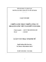
In Figure 2a the measured waveforms of transient thermal impedances ZthU(t), ZthUR(t) and ZthR(t)
for the transformer containing the nanocrystaline core are presented, whereas in Figure 2b – the
spectrum of thermal time constants of this transformer is shown. Parameters values of the thermal
model of the considered transformer are collected in Table 1.
a)
b)
1,2
RTN
RTN
1
20
ZthU(t)
0,8
15
ZthUR(t)
ai
ZthU(t), ZthUR(t), ZthR(t) [K/W]
25
0,6
10
0,4
ZthR(t)
5
0,2
0
0
0,1
1
10
100
1000
10000
t[s]
1
10
τthi [s]
100
1000
Figure 2. Transient thermal impedances in the transformer with the RTN core (a) and the spectrum of
thermal time constants of this transformer(b)
Table 1. Parameters values of the thermal model of the transformer with the RTN core.
transformer situated horizontally
transformer situated
vertically
parameter
ZthU(t)
ZthUR(t)
ZthR(t)
ZthU(t)
ZthUR(t)
Rth [K/W]
20.94
14.1
4.91
21.02
12.56
a1
0.826
1
0.606
0.608
1
a2
0.174
0.382
0.294
a3
0.012
0.098
359.1
361.7
597.9
385.4
310.1
τth1 [s]
13.35
373.6
47.3
τth2 [s]
40
98
τth3 [ms]
As one can notice in Figure 2a, the process of heating the core and winding of the transformer runs
slowly. The indispensable time to obtain the steady state exceeds 3000 s. It is worth paying attention
to the fact that the process of heating the winding runs more quickly, and the courses ZthUR(t) and
ZthR(t) are late with regard to the course ZthU(t) by even about 100 s. Additionally, it is visible that the
steady-state values of transient thermal impedance of the winding are even about 20% higher than the
values of transient thermal impedance between the winding and the core of this transformer. On the
other hand, the values of transient thermal impedance of the core are even four times smaller than
ZthU(t). The influence of orientation of the transformer in the vertical-line or in the horizontal-line on
the course of transient thermal impedance is visible only in the case of ZthUR(t), where the value of this
3
MicroTherm’2015 and SENM’2015
Journal of Physics: Conference Series 709 (2016) 012010
IOP Publishing
doi:10.1088/1742-6596/709/1/012010
parameter at the steady-state at vertical orientation is about 10% lower than at horizontal orientation of
this element.
In Figure 2b it is visible that the presented in Figure 2a waveforms of transient thermal impedances
can be described with the use of 1 to 3 thermal time constants, whereas the prevailing thermal time
constant accepts values in the range from 200 to 300 s. Orientation of the transformer does not
influence in an essential manner the value of thermal time constants.
In Figure 3 distribution of temperature on the surface of the investigated transformer with the RTN
core, obtained at the steady-state at different conditions of power supply of this transformer, are
shown. At dc stimulation the current of the primary winding is equal to about 9 A, whereas at the
stimulation of the primary winding with the sinusoidal current the amplitude is 2.4 A and frequency
5.5 kHz.
As one can notice for the transformer with the RTN core, at the stimulation with the direct current,
temperature on its surface at horizontal orientation accepts the values in the range from 40°C to 78°C,
at vertical orientation - the values of temperature from 40°C to 71°C, and at the stimulation of the
transformer with the sinusoidal current, temperature on its surface at horizontal orientation has the
values in the range from 30°C to 42°C. It should be noted that visible differences between the
temperature of the core and winding occur. At the power supply with the direct current the winding
has higher temperature, and at the power supply with the sinusoidal current - the core. Warmer areas
of the windings show the visible difference of temperatures not higher than several Celsius degrees,
similarly to the values of temperature on the surface of the core.
a)
b)
c)
Figure 3. Temperature distribution on the surface of the transformer with the RTN core at the
stimulation by: a) the dc current at horizontally situated transformer, b) the dc current at the vertically
situated transformer, c) the sinusoidal waveform of the current at the horizontally situated transformer
In Figure 4a the measured waveforms of transient thermal impedances ZthU(t), ZthUR(t) and ZthR(t)
for the transformer containing the powder core (RTP) are presented, whereas in Figure 4b – the
spectrum of thermal time constants of this transformer is shown. Parameters values of the thermal
model of the considered transformer are collected in Table 2.
a)
b)
1,2
RTP
RTP
1
20
ZthU(t)
0,8
ZthUR(t)
15
ai
ZthU(t), ZthR(t), ZthUR(t) [K/W]
25
10
ZthR(t)
0,6
0,4
5
0,2
0
0
0,1
1
10
100
1000
10000
1
t[s]
10
τthi [s]
100
1000
Figure 4. Transient thermal impedances in the transformer with the RTP core (a) and the spectrum of
thermal time constants of this transformer(b)
4
MicroTherm’2015 and SENM’2015
Journal of Physics: Conference Series 709 (2016) 012010
IOP Publishing
doi:10.1088/1742-6596/709/1/012010
Table 2. Parameters values of the thermal model of the transformer with the RTP core.
transformer situated horizontally
transformer situated vertically
parameter
ZthU(t)
ZthUR(t)
ZthR(t)
ZthU(t)
ZthUR(t)
ZthR(t)
Rth [K/W]
20.98
17.62
10.94
19.36
14.82
11.69
a1
0.717
0.922
1
0.784
1
0.341
a2
0.113
0.078
0.216
0.659
a3
0.153
a4
0.017
572.8
541.9
410.2
433.2
325.9
708.6
τth1 [s]
109.3
161.9
19.57
320
τth2 [s]
13.06
τth3 [s]
40
τth4 [ms]
As one can notice in Figure 4a the process of heating the core and the winding of the transformer
with the RTP core occurs similarly as for the transformer with the RTN core. The time indispensable
to obtain the steady state exceeds 3000 s. The obtained value ZthU(t) at the steady-state amounts to
about 22 K/W and it is practically the same as for the transformer with the RTN core, whereas values
ZthUR(t) and ZthR(t) for the transformer with the RTP core are considerably (even twice) higher than for
the transformer with the RTN core. At vertical orientation smaller by about 10 - 20 % values of ZthU(t)
and ZthUR(t) than for horizontal orientation of this transformer are obtained. In turn, the influence of
orientation of the transformer on the course ZthR(t) is omittably weak.
In Figure 4b it is visible that the presented in Figure 4a waveforms of transient thermal impedances
can be described with the use from 1 to 3 thermal time constants, whereas the prevailing thermal time
constant accepts values in the range from 200 to 500 s. It is visible that at vertical orientation of the
transformer deterioration of the prevailing thermal time constant by even about 50% is observed.
In Figure 5 distribution of temperature on the surface of the investigated transformer with the RTP
core obtained at the steady state at different conditions of stimulation of this transformer are shown. At
dc stimulation the current of the primary winding is equal to about 9 A, whereas at the stimulation of
the primary winding with the sinusoidal current the amplitude is 2.4 A and frequency 5.5 kHz.
a)
b)
c)
d)
Figure 5. The temperature distribution on the surface of the transformer with the RTP core at the
stimulation by: a) the dc current at the horizontally situated transformer, b) the dc current at the
vertically situated transformer, c) the sinusoidal waveform of the current at the horizontally situated
transformer, d) the sinusoidal waveform of the current at the vertically situated transformer
As one can notice for the transformer with the RTP core, at the stimulation with the direct current,
temperature on its surface at horizontal orientation accepts values in the range from 40°C to 89°C, at
vertical orientation - values of temperature in the range from 40°C to 73°C. In turn, at the stimulation
of the transformer with the sinusoidal current, temperature on its surface at vertical and horizontal
orientation accepts values of temperature in the range from 40°C to 61°C.
5
MicroTherm’2015 and SENM’2015
Journal of Physics: Conference Series 709 (2016) 012010
IOP Publishing
doi:10.1088/1742-6596/709/1/012010
It is proper to notice that visible differences between the temperature of the core and the winding
appear. However, warmer areas of windings show not big differentiation in temperature, not exceeding
several Celsius degrees, similarly to values of temperature on the surface of the core.
The measurements of temperature distribution on the surface of the transformer and the courses of
transient thermal impedances are performed also for transformers containing the ferrite core (RTF).
The results of such measurements are shown in Figure 6 for the transformer situated horizontally. As it
is visible, the obtained results qualitatively agree with the presented above results of measurements of
transformers with the RTP and RTN cores. Parameters values of the thermal model of the transformer
with the RTF core are collected in Table 3.
a)
b)
30
1,2
25
RTF
1
ZthU(t)
20
0,8
ZthUR(t)
15
ai
ZthU(t), ZthR(t), ZthUR(t) [K/W]
RTF
ZthR(t)
10
0,6
0,4
0,2
5
0
0
1
10
100
1000
1
10000
10
100
1000
τthi [s]
t[s]
Figure 6. Transient thermal impedances in the transformer with the RTF core (a) and the spectrum of
thermal time constants of this transformer(b)
Table 3. Parameters values of the thermal model of the transformer with the RTF core situated
horizontally.
transformer situated horizontally
parameter
ZthU(t)
ZthUR(t)
ZthR(t)
Rth [K/W]
24.55
14
11.9
a1
0.669
1
0.9
a2
0.221
0.1
a3
0.105
a4
0.005
415.8
384.35
413.6
τth1 [s]
125.1
195.4
τth2 [s]
10.1
τth3 [s]
40
τth4 [ms]
The obtained values of thermal resistance of the winding is equal to about 25 K/W, the mutual
thermal resistance between the winding and the core is equal to about 14 K/W and thermal resistance
of the core is equal to about 12 K/W. Thermal time constants accept values in the range from 10 s to
about 400 s. Therefore, time indispensable to obtain the steady state is shorter than for the other
considered transformers.
The temperature distribution on the surface of considered transformer are also measured and the
obtained results are similar to temperature distributions presented in Figure 5 for the RTP core.
4. Conclusions
In the paper the results of measurements of transformers’ own and mutual transient thermal
impedances in transformers containing cores made of different materials and temperature distribution
on the surface of these elements at the steady-state are presented. From the obtained results of
6
MicroTherm’2015 and SENM’2015
Journal of Physics: Conference Series 709 (2016) 012010
IOP Publishing
doi:10.1088/1742-6596/709/1/012010
measurements it results that the material of the core has a visible influence on the waveforms of
transient thermal impedances of the core included in the transformer, but it influences transient
thermal impedance of the winding in an omittably weak way. The highest value of this transient
thermal impedance is the highest for the transformer with the RTF core. Differences in the waveforms
of transient thermal impedance of the core can be a result of thermal conductance of the core material.
The highest values of the transient thermal impedance of the core is obtained for transformer with the
RTF core. In the steady state its value is even twice higher than the value of this parameter for the
transformer with the RTN core. On the other hand, the influence of transformers orientation on their
transient thermal impedances for the transformer situated vertically is visible, and typically smaller
values of these parameters are obtained.
The obtained distribution of the surface temperature of the transformer shows that inequality of
distribution of temperature in the examined transformers does not exceed a dozen or so kelvins. This
justifies the use of compact thermal models in the description of thermal properties of the examined
transformers.
5. References
[1] Barlik RJ, Nowak KM 2014 Energoelektronika. Elementy podzespoły, układy (Warszawa:
Oficyna Wydawnicza Politechniki Warszawskiej)
[2] Ericson R, Maksimovic D 2001 Fundamentals of Power Electronics (Norwell: Kluwer
Academic Publisher)
[3] Rashid MH 2007 Power Electronic Handbook (Academic Press, Elsevier)
[4] Górecki K, Rogalska M 2014 Microelectronics Journal 45 (12) 1795-1799
[5] Wilson PR, Ross JN, Brown AD 2002 IEEE Transactions on Power Electronics 17 (1) 55-65
[6] Van den Bossche A, Valchev VC 2005 Inductors and Transformers for Power Electronics
(Boca Raton: CRC Press, Taylor & Francis Group)
[7] Górecki K, Detka K, Zarębski J 2013 Pomiary wybranych parametrów i charakterystyk
materiałów i elementów magnetycznych Elektronika 1 18-22
[8] Górecki K, Zarębski J 2009 Microelectronics Reliability 49 (4) 424-430
[9] Górecki K, Rogalska M, Zarębski J 2014 Microelectronics Reliability 54 (5) 978-984
[10] Janke W 1992 Zjawiska termiczne w elementach i układach półprzewodnikowych (Warszawa:
WNT)
[11] Górecki K, Zarębski J 2014 IEEE Transactions on Components Packaging and Manufacturing
Technology 4 (3) 421-428
[12] Górecki K, Zarębski J 2010 IEEE Transactions on Components and Packaging Technologies 33
(3) 643-647
[13] Oettinger FF and Blackburn DL 1990 Semiconductor measurement technology: thermal
resistance measurements U. S. Department of Commerce NIST/SP-400/86
[14] Górecki K, Zarębski J, Detka K, Rogalska M 2013 Sposób i układ do pomiaru własnych
wzajemnych rezystancji termicznych elementu indukcyjnego European Patent Application EP
13460073
[15] Szekely V 1997 Microelectronic Journal 28 (3) 277-292
7