HIGH PERFORMANCE DRIVES_Chapter6_1
Bạn đang xem bản rút gọn của tài liệu. Xem và tải ngay bản đầy đủ của tài liệu tại đây (72.03 KB, 8 trang )
HIGH PERFORMANCE DRIVES
---------------------------------------------------------------------------------------------------------------------------------------
E Levi, 2001
92
5. CURRENT CONTROL TECHNIQUES IN HIGH PERFORMANCE
AC DRIVES
5.1. REVIEW OF CURRENT CONTROL METHODS
As both vector controlled induction machines and vector controlled SPMSM require current controlled
PWM inverter, then it is possible to discuss current control methods independently of the type of the
drive. In other words, all the current control techniques described further on are applicable in both
induction motor and SPMSM vector controlled drives.
Current controlled PWM inverter is the most frequent choice in high performance AC drives as
decoupled flux and torque control by instantaneous stator current space vector amplitude and position
control is achieved relatively easily. All the current control techniques essentially belong to one of the
two major groups. The first group encompasses all the current control methods that operate in the
stationary reference frame while the second group includes current control techniques with current
controllers operating in the rotational frame of reference. If the current control of an induction machine
is performed in rotational reference frame, decoupling of stator voltage equations substitutes local
current feedback loops in stationary reference frame, which suppress influence of stator voltage
equations.
Current control in stationary reference frame is usually implemented in an analogue fashion. The two
most common alternatives are hysteresis current controllers and ramp-comparison controllers. Both of
these have essentially already been implicitly looked at. In particular, the experimental results related to
the performance of a rotor flux oriented induction machine (Section 3.4.) are obtained on a drive that
utilises ramp comparison current controllers. Hence the current wave-forms of Figs. 3.16-3.18 apply to
this method of current control. On the other hand, the experimental results presented in Section 4.6. for
a vector controlled SPMSM machine apply to a drive that is equipped with hysteresis current controllers
(Figs. 4.13-4.16).
Approaches with three independent phase current controllers and two dependent current controllers in
α β
,
stationary frame of reference are possible. The most pronounced shortcoming of the hysteresis
current control is the variable inverter switching frequency over a period of output voltage. Current
control by ramp-comparison controllers overcomes this problem. Here current error serves as
modulating signal which is compared to the triangular carrier wave. Deviation of amplitude and phase
of phase currents with respect to commanded values unfortunately takes place and some compensation
has to be introduced, the common choice being a PI compensator. Another difficulty arises from a
possibility that multiple crossing of the carrier may occur if the frequency of the current error becomes
greater then the carrier frequency. This can be overcome by adding hysteresis to the controller. The
advantage of the ramp-comparison current control with respect to hysteresis current control is fixed and
constant inverter switching frequency (see current spectrum shown in Fig. 3.16, that contains only those
current harmonics that have a frequency situated around multiples of the inverter switching frequency).
Current control in stationary reference frame requires that current controllers process alternating
signals, that can be of a large frequency range. Furthermore, controller characteristics in steady-state
depend on the operating frequency and machine impedance. These shortcomings can be partially but
not completely eliminated by different modifications of the basic current control principles.
At low operating speeds the induced rotational electromotive force in the machine is small and current
control enables very good tracking between reference and actual currents, with respect to both
amplitude and phase. However at higher speeds, due to limited voltage capability of the inverter and
finite inverter switching frequency, tracking worsens and an error is met in both amplitude and phase of
actual currents compared to reference currents. This feature becomes very pronounced in the field
weakening region where the inverter operates very close to the voltage limit. The problem may be
HIGH PERFORMANCE DRIVES
---------------------------------------------------------------------------------------------------------------------------------------
E Levi, 2001
93
solved by removing the current controllers from stationary reference frame into the rotational reference
frame. The outputs of the current controllers then become voltage references in rotational reference
frame. If the inverter switching frequency is high enough, decoupling circuit for stator dynamics is
usually omitted and the machine is still treated as being current fed. In the field weakening region the
machine is usually fed with square-wave voltages and here the concept of current feeding has to be
abandoned. Decoupling circuit is included in the control system and the machine is treated as being fed
from a voltage source. The same concept of voltage feeding has to be applied in the base speed range as
well if the switching frequency of the inverter is low, this being the case with thyristor inverters utilised
in conjunction with vector controlled high power induction motors.
As already discussed in Chapter 4, current control in rotational reference frame is well suited to fully
digital realisation. The main advantage of this method of current control is that current controllers
(most frequently of PI type) process DC signals. As the current control is performed in rotational
reference frame, measured currents have to be transformed from stationary to rotational reference
frame. When current control in rotational reference frame is applied, different PWM methods may be
utilised for creation of the desired voltages at machine terminals. For example, sinusoidal PWM may be
selected or voltage space vector modulation may be chosen. As a separate sub-group predictive
methods of stator current space vector control may be identified. One method, for example, calculates
the required voltage space vector in such a way that the current vector error is kept within prescribed
boundaries at all times. State of the inverter does not change as long as it is predicted that the current
vector error will remain within defined boundaries. This approach enables minimisation of the inverter
switching frequency. The required voltage space vector is created by means of voltage space vector
modulation technique, utilising the two neighbouring voltage vectors and the zero voltage vector. It
should be noted that all the predictive methods significantly complicate the overall control system as
numerous additional calculation are required.
With respect to SPMSM drives, current control is again performed either in stationary or in field-
oriented reference frame. Fully digital versions of SPMSM drive usually employ current control in field
co-ordinates. The application of current controllers that operate in the stationary reference frame is
once more common in analogue and hybrid digital-analogue realisations, although fully digital
realisations are available as well. It should be noted that the control system structure is significantly
simpler in a SPMSM drive, compared to induction motor drive. Thus it is easier to achieve fully digital
control of a SPMSM drive.
Current control of SPMSM drives in stationary reference frame is again performed by the aid of
hysteresis controllers or ramp-comparison current controllers. The variety of complex hysteresis
modulation methods for VSI current control exist, however the most frequently used one is the classic
hysteresis method. The hysteresis window defines inverter switching frequency, which is, as already
stated, not constant over a period of output voltage. It is possible to overcome this shortcoming by the
aid of ramp-comparison controller application. In this case switching frequency is constant and
determined with the triangular carrier wave frequency. Both schemes can be implemented with either
two or three current controllers.
If the current control of' a SPMSM drive is performed in rotational reference frame, voltage space
vector modulation is the most frequent choice. If the inverter switching frequency and sampling rate are
sufficiently high, decoupling circuit is sometimes simplified or omitted. The usual choice for current
controllers in field-oriented reference frame is standard PI structure, although more complex predictive
techniques exist for SPMSM drives as well.
In what follows the most important current control techniques will be described. A SPMSM drive will
be considered as an example in all the cases, due to a considerably simpler control system structure.
Both current control in stationary reference frame and current control in rotational reference frame are
elaborated. The encompassed current control methods are hysteresis control and ramp comparison
control in stationary reference frame, and control in field co-ordinates with PI current controllers and
with phase voltage generation by means of voltage space vector modulation and by means of ramp
comparison method. In the latter case, the need for decoupling circuit application is addressed as well.
HIGH PERFORMANCE DRIVES
---------------------------------------------------------------------------------------------------------------------------------------
E Levi, 2001
94
5.2. CURRENT CONTROL METHODS
5.2.1. Current control in stationary reference frame - hysteresis controllers
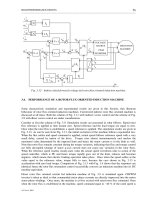
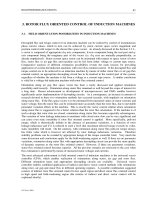
The structure of the SPMSM drive with hysteresis current control in the stationary reference frame is
depicted in Fig. 5.1. Either three independent controllers in three phase a,b,c reference frame can be
applied (as shown in Fig. 5.1), or the control can be performed by the aid of two controllers in
stationary two phase α,β reference frame. Comparative study of these two possibilities shows that there
are no differences in dynamic response of the drive.
The idea of hysteresis current control is in essence very simple and well suited for analogue realisation.
It has already been introduced in conjunction with a separately excited DC motor drive in Chapter 1
(Fig. 1.3). The principle remains the same when hysteresis current control is applied for an AC drive.
However, the reference currents (rather than a current) are now AC. Phase current references are in any
steady-state sine functions. Actual currents are allowed to deviate from their reference values for a
fixed value termed as hysteresis band. The discrepancy between actual and reference currents will vary
in time and will be either positive or negative. The values of the hysteresis band are the same for both
positive and negative variation. The state of the appropriate leg of the inverter bridge changes once
when the difference between actual and reference current exceeds hysteresis band. For example,
suppose that the upper switch in phase a leg is closed, while the lower switch is open. This state will be
preserved as long as the current error in phase a is within hysteresis band. However, when the actual
current in phase a becomes greater than the reference value plus hysteresis band, the upper switch will
be opened and the lower switch will be closed. Thus the actual current will be forced to reduce and fall
once more within the hysteresis band. As the actual current change in time is function of the drive
dynamics and operating state, the instants of inverter semiconductor switching cannot be predicted and
will vary. Furthermore the switching frequency of the inverter varies and is not constant even over one
cycle of the output frequency. The principle of hysteresis current control is illustrated in Fig. 5.2, where
the inverter leg voltage is shown as well. One clearly observes in Fig. 5.2 how the switching frequency
of the inverter varies from one cycle of operation to the other cycle. Periods of inverter switching are
denoted as T1, T2, T3 and T4 and one easily observes that T1 is the largest out of the four, while T4 is
the smallest.
In the system shown in Fig. 5.1 only speed controller is present, whose output becomes q-axis current
command. Stator d-axis current reference is set to zero. Note that Fig. 5.1 is essentially identical to Fig.
4.8 and that the only difference is the detailed representation of the hysteresis current controller in the
lower part of the figure.
5.2.2. Current control in stationary reference frame - ramp comparison control
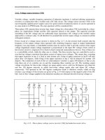
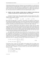
If the ramp comparison current control technique is applied, configuration of a SPMSM drive
corresponds to the one shown in Fig. 5.3. Current error is formed in stationary reference frame and
passed through PI current controllers. The outputs of the current controllers are phase voltage
references which are compared to the triangular carrier wave of the fixed frequency. As the triangular
carrier wave is of fixed frequency, while frequency of the current error varies, the ratio of these two
frequencies is not an integer and so-called asynchronous PWM of output voltages results in this way.
Asynchronous PWM in general leads to generation of unwanted subharmonics in the output voltage
wave-form. However if the triangular carrier wave frequency is high enough this effect can be
neglected as it will not have any serious impact on the drive behaviour. In general three carrier waves
are needed, one per phase. However if the triangular carrier frequency is high enough, one carrier wave
may be utilised for all the three phases as is done here.
HIGH PERFORMANCE DRIVES
---------------------------------------------------------------------------------------------------------------------------------------
E Levi, 2001
95
Diode
bridge DC link PWM SPM
rectifier inverter SM
hysteresis i
a
i
b
i
c
position
current control sensor
ω*Pi
qs
*i
αs
*i
a
* −
Iexp2i
b
* −
− (jθ)3i
c
* −
ω i
ds
*=0 i
βs
*
sin /
θ
cos
d/dt
Comparator
with hysteresis
Upper
switch
i
a
* ∆i
a
IGBT
drivers
−
i
a
Lower
switch
Fig. 5.1 - Hysteresis current control of a SPMSM drive.
h = hysteresis band
i
a
i
a
*
i
a
*+h
t
i
a
*-h
v
An
V
DC
t
T1 T2 T3 T4
Fig. 5.2 - Principle of hysteresis current control: currents and a leg voltage.
HIGH PERFORMANCE DRIVES
---------------------------------------------------------------------------------------------------------------------------------------
E Levi, 2001
96
It should be noted that the structures of the two drives shown in Figs. 5.1 and 5.3 are identical and that
the only difference is in the method of current control applied. In other words, only the local current
control loops used to control the inverter differ (lower portions of Figs. 5.1 and 5.3). Generation of the
inverter leg voltages using ramp comparison control is illustrated in Fig. 5.4.
Diode
bridge DC link PWM SPM
rectifier inverter SM
Ramp comparison i
a
i
b
i
c
position
current control sensor
ω
*Pi
qs
*i
α
s
*i
a
*
−
Iexp2i
b
*
−
− (jθ)3i
c
* −
ω i
ds
*=0 i
β
s
*
sin /
θ
cos
d/dt
i
a
*PIv
a
*
controller P Power
− i
a
stage
i
b
*PIv
b
*ofthe
controller W
−
i
b
i
c
*PIv
c
*PWM
controller M VSI
− i
c
Triangular
carrier wave
Fig. 5.3 - Ramp comparison current control of a SPMSM drive.
5.2.3. Current control in field co-ordinates with voltage space vector modulation
The SPMSM drive with current control in field co-ordinates is shown in Fig. 5.5. Current controllers
are of the PI structure. Block PWM denotes voltage space vector modulator. On the basis of the
reference voltage space vector, actual voltage space vector is generated by the aid of two adjacent