Advanced Verification Flow part 2
Bạn đang xem bản rút gọn của tài liệu. Xem và tải ngay bản đầy đủ của tài liệu tại đây (28.95 KB, 6 trang )
[ Team LiB ]
15.2 Assertion Checking
The traditional verification flow discussed in the previous section is a black box
approach, i.e., verification relies only on the knowledge of the input and output behavior
of the system.
Many other verification methodologies have evolved over the past few years to
complement the traditional verification flow discussed in the previous section. In this
section and the following sections, we explain some of these new verification
methodologies that use the white box verification approach, i.e., knowledge of the
internal structure of the design is needed for verification.
Assertion checking is a form of white box verification. It requires knowledge of internal
structures of the design. The main purpose of assertion checkers is to improve
observability.
Assertions are statements about a design's intended behavior. There are two types of
assertions:
•
Temporal assertions – they describe the timing relationship between signals.
•
Static assertions – they describe a property of a signal that is always true or false.
Assertions may be used in the RTL code to describe the intended behavior of a piece of
Verilog HDL code. The following are examples of such behavior:
•
An FSM state register should always be one-hot.
•
The full and empty flags of a FIFO should never be asserted at the same time.
Assertions can also be used to describe the behavior of the internal or external interface
of a chip. For example, the acknowledge signal should always be asserted within five
cycles of the request signal. Assertions may be verified in simulation or by using formal
methods.
Assertions do not contribute to the element being designed; they are usually treated as
comments for logic synthesis. Their sole purpose is to ensure consistency between the
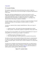
designer's intention and the design that is created. Figure 15-7
shows the interfaces at
which assertions could be placed in a FIFO-based design.
Figure 15-7. Assertion Checks
Assertion checks can be used with the traditional verification flow described in Section
15.1, Traditional Verification Flow. Assertion checks are placed by the designer at
critical points in the design. During simulation, if there is a failure at that point, the
designer is notified.
Assertion-based verification (ABV) has the following advantages:
1. ABV improves observability. It isolates the problem close to the source.
2. ABV improves verification efficiency. It reduces the number of engineers
involved in the debugging process. Engineers notified when there are bugs are
having to look through waveforms and log files for hours to find bugs. Thus, the
debug process is greatly simplified.
Appendix E
, Verilog Tidbits, contains further information on popular assertion-checking
tools.
[ Team LiB ]
[ Team LiB ]
15.3 Formal Verification
A well-known white-box approach is formal verification, in which mathematical
techniques are used to prove an assertion or a property of the design. The property to be
proven may be related to the chip's overall functional specification, or it may represent
internal design behavior. Detailed knowledge of the behavior of design structures is often
required to specify useful properties that are worth proving. Thus, one can prove the
correctness of a design without doing simulations. Another application of formal
verification is to prove that the architectural specifications of a design are sound before
starting with the RTL implementation.
A formal verification tool proves a design property by exploring all possible ways to
manipulate a design. All input changes must conform to the constraints for legal
behavior. Assertions on interfaces act as constraints to the formal tool to constrain what is
legal behavior on the inputs. Attempts are then made to prove the assertions in the RTL
code to be true or false. If the constraints on the inputs are too loose, then the formal
verification tool can generate counter-examples that rely on illegal input sequences that
would not occur in the design. If the constraints are too tight, then the tool will not
explore all possible behavior and will wrongly report the design as "proven."
Figure 15-8
shows the verification flow with a formal verification tool. In the best case,
the tool either proves a particular assertion absolutely or provides a counter-example to
show the circumstances under which the assertion
[4]
is not met.
[4]
Assertions are not used simply to increase observability. In formal verification, they
are used as constraints. The formal verification tool explores the state space such that it
proves the assertion absolutely or produces a counter-example. Thus, assertions also
increase controllability, i.e., they control how the formal verification tool explores the
state space to prove a property.
Figure 15-8. Formal Verification Flow
Since formal verification tools explore a design exhaustively, they can run only on
designs that are limited in size. Typically, beyond 10,000 gates, absolute formal proofs
become too hard and the tool blows up in terms of computation time and memory usage.
The limitations on formal verification tools are not based on number of lines. They are
based on the complexity of the assertions being proven and the design structure. The
limitation lies in the number of cycles the algorithm can reach from the seed state(Formal
verifications tools often use reset as the seed state).
To circumvent the problems of formal verification, semi-formal techniques are used.
15.3.1 Semi-formal Verification
Semi-formal verification combines the traditional verification flow using test vectors with
the power and thoroughness of formal verification. Semi-formal techniques have the
following components:
1. Semi-formal methods supplement, but do not replace, simulation with test vectors.
2. Embedded assertion checks define the properties targeted by formal methods.
3. Embedded assertion checks define the input constraints.
4. Semi-formal methods explore a limited state space exhaustively from the states
reached by simulation, thus maximizing the effect of simulation. The exploration
is limited to a certain point around the state reached by simulation.
During a Verilog simulation, seed states are captured to serve as starting points for formal
methods. Then formal methods start from the seed states and try to prove the assertions
completely or describe stimulus sequences that will violate these assertions. The semi-
formal tool proves properties exhaustively in a limited exploration space starting from
these seed states, thus quickly identifying many corner-cases that would have been
detected only by extensive simulation test suites. Figure 15-9
shows the verification flow
with a semi-formal tool.
Figure 15-9. Semi-formal Verification Flow
Formal and semi-formal verification methods have recently received a lot of attention
because of the increasing complexity of designs. Appendix E
, Verilog Tidbits, contains
further information on popular tools that employ formal and semi-formal verification
methods.
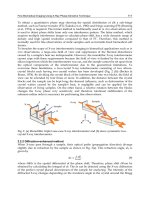
15.3.2 Equivalence Checking
After logic synthesis and place and route tools create gate level netlist and physical
implementations of the RTL design, it is necessary to check whether these
implementations match the functionality of the original RTL design. One methodology is
to re-run all the test vectors used for RTL verification, with the gate level netlist and the
physical implementation. However, this methodology is extremely time consuming and