Logic kỹ thuật số thử nghiệm và mô phỏng P6
Bạn đang xem bản rút gọn của tài liệu. Xem và tải ngay bản đầy đủ của tài liệu tại đây (350.41 KB, 40 trang )
283
Digital Logic Testing and Simulation
,
Second Edition
, by Alexander Miczo
ISBN 0-471-43995-9 Copyright © 2003 John Wiley & Sons, Inc.
CHAPTER 6
Automatic Test Equipment
6.1 INTRODUCTION
Digital circuits have always been designed to operate beyond the point where they
could be reliably manufactured on a consistent basis. It is a simple matter of eco-
nomics: By pushing the state of the art—that is, aggressively shrinking feature sizes,
then testing them and discarding those that are defective—it is possible to obtain
greater numbers of ICs from a single wafer than if they are manufactured with more
conservative feature sizes (cf. Section 1.8 for more discussion on this practice).
This strategy depends on having access to complex, and sometimes very expen-
sive, test equipment. This strategy also depends on being able to amortize tester cost
over many hundreds of thousands, or millions, of ICs. As ICs become more complex,
running at faster clock speeds, with greater numbers of I/O pins, requirements on the
tester become greater. More pins must be driven and monitored. Tolerances grow
increasingly tighter, and there is less margin for error. Clock skew and jitter must be
controlled more tightly, and the increasing amount of logic, running at ever higher
clock speeds, requires the ability to switch greater amounts of current in less time.
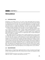
Early testers were quite simple: Input pins were driven by stimuli stored in
memory. After some predetermined clock cycle the output pins were strobed and
their responses compared to expected responses (cf. Figure 6.1). Many early testers
were designed and manufactured by end users, particularly mainframe vendors.
With time, however, and the increasing complexity of the ICs and PCBs being
tested, it became prohibitively expensive to design and build these testers. Compa-
nies were formed for the explicit purpose of designing and building complex testers
and, although these testers were quite expensive, it was nevertheless more economi-
cal to buy than to build in-house.
Over the years, many tester architectures and test strategies have evolved in order
to locate defects in ICs and PCBs and provide the highest possible quality of
delivered goods at the lowest possible price.This chapter provides a very brief over-
view of some of the more important highlights and concepts involved in applying
test stimuli to digital circuits and monitoring their response. Space does not permit a
284
AUTOMATIC TEST EQUIPMENT
Figure 6.1
Basic test configuration.
more thorough investigation of the many tester architectures and strategies that have
been devised to test digital devices during design debug and manufacturing test.
6.2 BASIC TESTER ARCHITECTURES
Functional testers apply stimuli to input pins of a device-under-test (DUT) and
sample the response at output pins after sufficient time has elapsed to permit signals
to propagate and settle out. The tester then compares sampled response to expected
response in order to determine whether the DUT responded correctly to applied
stimuli. Depending on their capabilities, these testers can be used to test for correct
function, characterize and debug initial parts, and perform speed binning.
6.2.1 The Static Tester
Functional testers can be characterized as static or dynamic. A
static tester
, such as
the one depicted in Figure 6.1, applies all signals simultaneously and samples all
output pins at the end of the clock period. Device response is compared to the
expected response and, if they do not match, the controlling computer is given
relevant information such as the vector number and the pin or pins at which the
mismatch was detected. The static tester does not attempt to accurately measure
when
events occur. Therefore, if a signal responds correctly but has excessive propa-
gation delay along one or more signal paths, that fact may not be detected by the
static tester. These testers are primarily used for go–nogo production testing.
A general-purpose tester must have enough pins to drive the inputs and to monitor
the outputs of the DUT. In fact, in order to be general purpose, the tester must have
enough pins to drive and sample the I/Os of the largest DUT that might be tested by
that tester. Furthermore, since it is not known how many of the I/Os on the DUT are
inputs, and how many are outputs, it must be possible to configure each of the tester
pins as an input or as an output. If a device has more pins than the tester, it may be
possible to extend the capabilities of the tester through the use of clever techniques
such as driving two or more inputs from a single tester channel and/or multiplexing IC
output pins to a single tester channel where they may be sampled in sequence.
DUT
s
t
i
m
u
l
i
CPU
r
e
s
p
o
n
s
e
e
x
p
e
c
t
Pass/Fail
Test
pgm
BASIC TESTER ARCHITECTURES
285
When considering a tester for purchase, its maximum operating speed may be an
important consideration, depending on the purpose for which it is being purchased.
But other factors, including accuracy, resolution, and sensitivity, must be given
equal weight.
1
Accuracy
is a measure of the amount of uncertainty in a measure-
ment. For example, if a voltmeter is rated at an accuracy of ±0.1% and measures
5.0 V, the true voltage may lie anywhere between 4.95 V and 5.05 V.
Resolution
refers to the degree to which a change can be observed. Referring again to the volt-
meter, if it is a digital voltmeter, its resolution is expressed as a number of bits. How-
ever, the last few bits may not be meaningful if measurements are being taken in a
noisy environment. If the noise is random and there is a need for greater resolution,
samples can be averaged. This is done at the expense of sampling rate.
Sensitivity
describes the smallest absolute amount of change that can be detected
by a measurement. For the voltmeter, sensitivity might be expressed in millivolts or
microvolts. Note that these three factors do not necessarily depend on one another. A
device may have high resolution or high sensitivity but may not necessarily meet
accuracy requirements for a particular application. Moreover, a device may have
high sensitivity, but its ability to measure small signal changes may be limited by
other devices in the test setup such as the cables used to make the measurements.
Tester programming is another important consideration. Test programs that are
used to control testers are normally created on general-purpose computers. They
may be derived from design verification vectors, from an ATPG, or from vectors
specifically written to exercise all or part of a design in order to uncover manufactur-
ing defects. When the developer is satisfied that the test program is adequate, it is
ported to the tester.
The tester will have facilities similar to those found on a general-purpose com-
puter, including tape drives, a modem and/or network card, and storage facilities
such as a hard drive. These facilities allow the tester to read a final test program that
exists in ASCII form and compile it into an appropriate form for eventual execution
on the tester. Other facilities supported by the computer include the ability to debug
tester programs on the tester. This may include features such as printing out failing
response from the DUT, altering input values or expect values, masking failing pins
and switching mode from stop on first failure to stop after
n
failures, for some arbi-
trary
n
.
When the compiled program is needed, it is retrieved from hard disk. The part of
the test program that defines input stimuli and expected response is directed to
pin
memory
. Behind each channel on the tester there is a certain amount of pin memory
capable of storing the stimuli and response for that particular channel. The goal is to
have enough memory behind each tester channel to store an entire test sequence.
However, testers may allow pin memory to be reloaded with additional stimuli and
response from the hard drive. When refreshing pin memory, each memory load may
require an initialization sequence, particularly if the DUT contains dynamic parts.
Some parts may also run very hot, and the additional time on the tester, waiting for
pin memory to be updated, may introduce reliability problems for the part.
Many of the pins on a typical DUT may be bidirectional pins, acting sometimes
as inputs and sometimes as outputs. Therefore, on a general-purpose tester, it must
286
AUTOMATIC TEST EQUIPMENT
be possible to dynamically change the function of the pins so that during execution
of a test a tester channel may sometimes drive the pin that it is connected to, and
sometimes sample that same pin. This and other pieces of information must be pro-
vided in the test program developed by the test engineer. Other information that
must be provided includes information such as voltage and current limits. A subse-
quent section will examine a tester language designed to configure tester channels
and control the tester.
6.2.2 The Dynamic Tester
It is increasingly common for ICs to be designed to operate in applications where, in
order to operate correctly with other ICs mounted on a complex PCB, they must
adhere closely to propagation times listed in their data sheets. In such applications,
excessive delays can be a serious problem. Isolating problems on a PCB caused by
excessive propagation delays is especially difficult when all the ICs have passed
functional test and are assumed to be working correctly. It is also possible that cor-
rect behavior of an IC involves outputting short-lived pulses that are present only
briefly but are nevertheless necessary in order to trigger events in other ICs. These
situations, excessive delay and appearance of pulses at output pins, are not handled
well by static testers. Other challenges to static testers include application of tests to
devices such as dynamic MOS parts that have minimum operating frequencies.
To exercise devices at the clock frequency for which they were designed to oper-
ate, to schedule input changes in the correct order, and to detect timing problems and
pulses, the
dynamic tester
is employed. It is also sometimes called a
high-speed
functional tester
or a
clock rate tester
. It can be programmed to apply input signals
and sample outputs at any time in a clock cycle. It is more complex than the static
tester since considerably more electronics is required. Whereas many functions in
the static tester are controlled by software, in the dynamic tester they must be built
into hardware in order to provide resolution in the picosecond range.
The dynamic tester solves some problems, but in doing so it introduces others.
Whereas the static tester employs low slew rates (the rate at which the tester changes
signal values at the circuit inputs), the dynamic tester must employ high slew rates
to avoid introducing timing errors. However, high slew rates increase the risk of
overshoot, ringing, and crosstalk.
2
Programming the tester also requires more effort
on the part of the test engineer, who must now be concerned not only with the signal
values on the circuit being tested but also with the time at which they occur. The task
is further complicated by the fact that these timings are also dynamic, being able to
change on a vector-by-vector basis, as different functions inside the IC control or
influence the signal directions and logic values on the I/O pins.
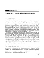
The architecture of a dynamic tester is illustrated in Figure 6.2.
3
The test pattern
source is the same set of patterns that are used by the static tester. However, they are
now controlled by timing generators and wave formatters. The test patterns are
initially loaded into pin memory and specify the logic value of the stimulus or the
expected response. The remaining circuits specify when the stimulus is to be applied
or when the response is to be sampled. The system is controlled by a master clock
BASIC TESTER ARCHITECTURES
287
Figure 6.2
Architecture of shared-resource tester.
that determines the overall operating frequency of the board and controls a number
of timing generators. Each of the timing generators employs delay elements and
other pulse-shaping electronics to generate a waveform with programmable place-
ment of leading and trailing edges. The placement of these edges is determined by
the user and can be specified to within a few picoseconds, depending on the accu-
racy of the tester.
The number of timing generators used in a functional tester depends on whether
it is a shared resource or tester-per-pin architecture. A
shared resource
tester
(Figure 6.2) contains fewer timing generators than pins and employs a switching
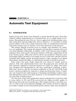
matrix to distribute the timing signal to tester pins, whereas the
tester-per-pin
archi-
tecture (Figure 6.3) employs a timing generator for each tester pin. Programming the
shared resource tester requires finding signals that have common timing and con-
necting them to the same tester channel so that they can share wave formatters and
pin electronics. The switching matrix in the shared resource tester can contribute to
skewing problems, so eliminating the switching matrix makes it easier to deskew
and thus improve the accuracy of the tester.
4
Another factor that makes the tester-
per-pin more accurate is the fact that there is always one fixed-length signal path to
the DUT, so the timing can be calibrated for that one path.
Figure 6.3
Architecture of tester-per-pin tester.
Master
clock
DUT
Timing
generators
N × M Switching
matrix
Wave
formatters
Pin
electronics
Master
clock
DUT
Timing
generators
Wave
formatters
Pin
electronics
288
AUTOMATIC TEST EQUIPMENT
The programming of a tester for a given DUT requires a file containing logic
stimulus values to be applied and expected values at the DUT outputs. However,
other files are required, including a
pin map
and a file with detailed instructions as to
how the waveforms are to be shaped by the pin electronics. The pin map identifies
the connectivity between the tester and the DUT. The input stimuli and the expected
output responses are stored in tester memory in some particular order. For example,
pins 1 through 8 of the DUT may be an eight-bit data path. Furthermore, this data
path may be bidirectional. When the pins on the DUT are connected to channels on
the tester, it is important that the 8-bit data path on the DUT be associated with the
eight channels that are driving or sampling that data path.
6.3 THE STANDARD TEST INTERFACE LANGUAGE
Tester programming languages have tended to be proprietary. Because testers from
different companies emphasize different capabilities, it was argued that proprietary
languages were needed to fully and effectively take advantage of all of the unique
features of a given tester. A major problem with this strategy was that if a semicon-
ductor company owned testers from two or more tester companies, test program
portability presented a major problem. If the company wanted to use both of these
testers to test a device in a production environment, its engineering staff had to have
experts knowledgeable in the test languages provided by each of these testers. For a
small company, this could be a major drain on assets, and a single-test engineer
might find it difficult to keep up with all the nuances, as well as changes, revisions,
and so on, for multiple-test programming languages.
The Standard Test Interface Language (STIL) was designed to provide a common
programming language that would let test engineers write a test program once and
port it to any tester. It has been approved by the Institute of Electrical and Electronic
Engineers (IEEE) as IEEE-P1450.
5
Its goal is to be “tester independent.”
6
This is
achieved by having the language represent data in terms of its intent rather than in
terms of a specific tester.
7
Thus, it is left to the tester companies to leverage to full
advantage all of the features of their particular testers, given a test program written
in STIL.
STIL provides support for definition of input stimuli and expected response data
for test programs. But it also provides mechanisms for defining clocks, timing infor-
mation, and design-for-test (DFT) capabilities in support of scan-based testing. One
of its capabilities is a ‘UserKeywords’ statement that supports extensibility by
allowing the user to add keywords to the language. STIL was initiated as a tool for
describing test programs for testers, but its flexibility and potential have made it
attractive as a tool for defining input to simulation and ATPG tools. It also offers an
opportunity to reduce the number of data bases. Rather than have several data bases
to capture and hold data and results from different phases of the design, test, and
manufacturing process, STIL offers an opportunity to consolidate these data bases
with a potential not only to reduce the proliferation of files, but also to reduce the
number of opportunities for errors to creep into the process. Already there is a
THE STANDARD TEST INTERFACE LANGUAGE
289
growing interest in adding enhancements to facilitate the use of STIL in areas where
it was not originally intended to be used.
8
An example of usage of STIL is presented here to illustrate its use. The circuit
will be an 8-bit register with inputs
D
0
–
D
7
and outputs
Q
0
–
Q
7
. It will have an
asynchronous, active low clear, an active-high output OE, and a clock with active
positive edge. When OE is low, the output of the register floats to Z.
Example
STIL 0.0;
// 8-bit Reg. with clock and clear
Signals {
CLK In;
CLR In;
OE In;
D0 In; D1 In; D2 In; D3 In; D4 In; D5 In; D6; In; D7 In;
Q0 Out; Q1 Out; Q2 Out; Q3 Out; Q4 Out; Q5 Out; Q6 Out;
Q7 Out;
}
SignalGroups {
INBUS ‘D0 + D1 + D2 + D3 + D4 + D5 + D6 + D7’;
OUTBUS ‘Q0 + Q1 + Q2 + Q3 + Q4 + Q5 + Q6 + Q7’;
ALL ‘CLK + CLR + OE + INBUS + OUTBUS’;
}
Spec timingspec {
Category prop_time {
tplh { Min ‘2.00ns’; Typ ‘3.00ns’; Max ‘4.00ns’; }
tphl { Min ‘2.00ns’; Typ ‘3.00ns’; Max ‘4.00ns’; }
tpzl { Min ‘5.25ns’; Typ ‘6.00ns’; Max ‘7.00ns’; }
tpzh { Min ‘4.50ns’; Typ ‘5.50ns’; Max ‘6.50ns’; }
tplz { Min ‘3.45ns’; Typ ‘4.20ns’; Max ‘5.75ns’; }
tphz { Min ‘3.45ns’; Typ ‘4.20ns’; Max ‘5.75ns’; }
strobe_width ‘3.00ns’;
}
}
Selector typical_mode {
tplh Typ;
tphl Typ;
tpzl Typ;
tpzh Typ;
tplz Typ;
tphz Typ;
290
AUTOMATIC TEST EQUIPMENT
}
Timing timing_info {
WaveformTable first_group {
Period ‘50ns’:
Waveforms {
CLR { 0 { ‘0ns’ ForceDown; }}
CLR { 1 { ‘0ns’ ForceUp; }}
OE { 01 { ‘0ns’ ForceDown/ForceUp; }}
CLK { 01 { ‘0ns’ ForceDown/ForceUp;
CLK_edge: ‘25ns’ ForceUp/Forcedown; }}
INBUS { 01 { ‘0ns’ ForceDown/ForceUp; }}
OUTBUS { L { ‘0ns’ X; ‘CLK_edge+tpzl’ l;
‘@+strobe_width’ X;}
H { ‘0ns’ X; ‘CLK_edge+tpzh’ h; ‘@+strobe_width’ X;}
D { ‘0ns’ X; ‘CLK_edge+tplz’ t; ‘@+strobe_width’ X;}
U { ‘0ns’ X; ‘CLK_edge+tpzh’ t; ‘@+strobe_width’ X;}
F { ‘0ns’ X; ‘CLK_edge+tphl’ l; ‘@+strobe_width’ X;}
R { ‘0ns’ X; ‘CLK_edge+tplh’ h; ‘@+strobe_width’ X;}
X { ‘0ns’ X; } }
} // end Waveforms
} // end WaveformTable first_group
} // end Timing
PatternBurst stimuli {
PatList { exercise_part; }
}
PatternExec {
Timing timing_info;
Selector typical_mode;
Category prop_time;
PatternBurst stimuli;
} // end PatternExec
Pattern exercise_part {
W first_group;
// first vector must define states on all signals
V { ALL=00000000000XXXXXXXX; } // clear the reg’s,
// don’t measure
V { CLR=1; OUTBUS=XXXXXXXX; } // release the clear,
// don’t measure
V { ALL=01100000000LLLLLLLL; } // outputs enabled
THE STANDARD TEST INTERFACE LANGUAGE
291
V { CLK=0; INBUS=FF; OUTBUS=RRRRRRRR; } // all switching
// to high
V { INBUS=55; OUTBUS=FHFHFHFH; } // some switch to low
} // end patterns
The first line in an STIL program identifies the STIL version. That is followed by
a comment. Comments in STIL follow the format employed in the C programming
language. A pair of slashes (//) identify a comment that extends to the end of a line.
Comments spanning several lines are demarcated by /* ... */.
Immediately following the comment is a block that identifies the I/O signals used
in the design. Each signal in the design is identified as an In, Out, or InOut. Signals
may be grouped for convenience, using the SignalGroups block. The inputs D0
through D7 to the individual flip-flops of the 8-bit register are grouped and assigned
the name INBUS. In similar fashion the outputs of the 8-bit register are grouped and
given the name OUTBUS. Then, the entire set of input and output signals are
grouped and assigned the name ALL. These groupings prove convenient later when
defining vectors.
The Spec block defines specification variables. The Spec block is assigned a
name, but it is for convenience only; the name is not used in any subsequent refer-
ence. In this example a Category is defined and assigned the name prop_time. Several
categories can be defined and used at different places in the test program. Six of the
variables in category prop_time are propagation delays that will be used later when
defining the WaveformTable. The names of the Spec entries are arbitrary and, in fact,
any number of entries could be used in the Spec block. For example, a user may have
a legitimate reason to define unique propagation times from X to Z, 0, and 1.
Three values, a minimum, typical, and maximum, are assigned to each of the six
variables in the Spec block. A seventh variable called strobe_width has one value
that defines the duration of a strobe measurement on an output. The Selector block
determines which of the Spec values to use. There are four possibilities: Min, Typ,
Max, or Meas. Meas values are determined and assigned during test execution time;
they are not explicitly specified in the Spec information.
The Timing block follows the Selector block. It is given the name timing_info. It
contains definitions for one or more WaveformTables. In the example presented here
there is just one WaveformTable, and it is assigned the name first_group. The first
statement assigns a period of 50 ns to all the test vectors that use first_group. Then,
some Waveforms are defined. The first one is for CLR, the clear signal. The number
0 follows the signal name CLR. It is called a WaveformChar, abbreviated WFC.
Although any character may be used to represent the waveform following the WFC,
it is good practice to use a character that has some recognizable meaning because
the WFC will be used in the ensuing vectors.
A signal may have several waveforms, but each one must have a different WFC.
In STIL a waveform is a series of time/event pairs. In the waveform for CLR the
keyword ForceDown follows the time 0 ns. So, at time 0 a ForceDown event occurs;
CLR is driven low if it had previously been at a high value. If a signal is in the off
(Z) state, it is turned on and driven low. Notice that in the example given above,
292
AUTOMATIC TEST EQUIPMENT
there are two waveforms for CLR that have identical timing, so they could actually
be merged. However, they were kept separate for illustrative purposes.
Merging is illustrated by the waveform for the output enable OE. At 0 ns OE
could switch to either 0 or to 1. Therefore a single WFC 01 represents this time/
event pair, and both possibilities are described on that one line. The first entry,
ForceDown, corresponds to WFC 0. The second entry, following the slash, corre-
sponds to WFC 1. The character string 01 is called a WFC_LIST.
The next waveform defines the behavior for CLK. Like OE, the CLK signal uses
a WFC_LIST. One new thing to note here is the introduction of an event_label defi-
nition called CLK_edge. Labels defined in this way are scoped to the Wave-
formTable in which they are defined. The label is useful in relating subsequent
events to the clock edge. The CLK waveform is followed by a waveform for INBUS.
It also has a rather simple waveform. However, one distinction here lies in the fact
that the waveform applies to all the signals D0 through D7.
The last entry in the WaveformTable is for OUTBUS. Recall that it is the set of
outputs Q0 through Q7. There are seven entries for OUTBUS, and each has its own
WFC. The first entry for OUTBUS has an L as its WFC. At time 0 ns the tester is
told to look for an X on the output. This is simply a way to tell the tester not to mea-
sure at this time. Then, at time CLK_edge + tpzl the tester is told to expect
l
(the let-
ter
l
), which is a compare logic low window. In the CLK waveform CLK_edge was
defined to occur at 25 ns. So, the tester should start monitoring the OUTBUS at 25
ns + tpzl. Since Typ values were selected by the Selector, and the Typ value for tpzl
was defined to be 6.00 ns, the tester should start monitoring at 31.00 ns. The next
field begins with the @ symbol. The @ symbol is used to refer to present time,
which was defined to be CLK_edge + tpzl in the previous field. So @+strobe_width
is 31.00 ns + 3.00 ns, meaning that the tester should continue to monitor OUTBUS
until 34.00 ns.
Each of the first six entries for OUTBUS corresponds to one of the six entries in the
Spec block. The seventh entry is for those vectors where the output is unknown, and
the tester is instructed not to strobe. The letters
l
,
h
, and
t
are called events and indicate
a window strobe. The letter
t
is used when the response is supposed to be high imped-
ance during the entire strobe window. Several other events are defined in P1450.
The PatternBurst block, with the name “stimuli,” specifies a list of patterns that
are executed in a single execution. The example contains one PatList called
“exercise_part.” There could be several pattern lists, with the user choosing different
sets of patterns for different runs. One of the pattern lists could be a common initial-
ization sequence that several designers or test engineers use to ensure consistency
across several test programs. The PatternExec follows the PatternBurst block; it con-
tains the commands that pull together all the information needed to perform a test
run. The PatternBurst entry is required, the other three entries are optional. If there
are multiple entries for Category, Selector, or Timing, then the entry is required in
the PatternExec block to avoid ambiguity. In the example above, these blocks only
had single entries, so they could have been omitted. It might, however, be good cod-
ing practice to include them as reminders for possible expansion of the test program
in the future.
USING THE TESTER
293
We finally come to the list of patterns that will be applied to the DUT. The set of
patterns is given the name exercise_part, the same name that appears in the PatList
that is part of the PatternBurst block. The first line following the open parenthesis
begins with the letter W, it selects the WaveformTable entry that is to be used. The
first_group following the W identifies the entry in the WaveformTable. It is used
exclusively in this small example, but in a large, complex circuit there could be sev-
eral WaveformTable entries. Suppose OUTBUS in the above example were bidirec-
tional. Then there would need to be a WaveformTable entry describing its behavior
when OUTBUS is acting as an output, and another to describe its behavior when it is
acting as an input.
The next entry in the vector list is a comment. A test program, like many other
programs, may take on a life of its own, existing for many years after the original
creator has gone on to some other calling. It is a good practice to identify what is
supposed to be accomplished in each part of a test program, for your benefit as well
as some other individual far in the future, since you are the one who may have to
debug it or modify it to test an ECO (engineering change order) at some future date.
The V at the beginning of the next line defines one vector. The first vector assigns
values to all the inputs and specifies X’s on all the outputs. The tester interprets this
to mean that it is not required to measure the output values. The next vector causes
the CLR to be released. Since the output has not been enabled, the outputs are float-
ing. However, in this example the tester is told not to measure the outputs. On the
third vecor the outputs are enabled and the expected response is listed. Notice that in
the WaveformTable the CLK signal is 0 for 25 ns and 1 for 25 ns when the WFC is a
0. Hence, this set of vectors has a period of 50 ns. It also should be mentioned that if
a signal is not specified in a vector, it retains its last value, so it was not actually nec-
essary to specify CLK = 0 in the fourth vector.
It is beyond the scope of this text to explore all of the capabilities of STIL. The
interested reader can consult the IEEE Standard P1450, which contains, in addition
to the formal specification of the STIL language, many illustrative examples. As pre-
viously pointed out, the language is intended to be independent of any specific tester
architecture. It is possible, of course, that a particular program written in STIL calls
for capabilities beyond that which a particular tester is capable of, but so long as a
tester has the capabilities called for in a particular test program, then it is the respon-
sibility of a compiler provided by that tester vendor to translate the STIL program
into a binary form acceptable to the target tester. If an IC manufacturer has several
different testers, then, in theory, at least, the same STIL test program should be able
to be ported to any of the testers simply by recompiling it. This gives the IC manu-
facturer much greater flexibility in allocating resources as products mature and
needs change.
6.4 USING THE TESTER
Digital testers are used to functionally test ICs and PCBs in order to determine
whether they respond correctly to applied stimuli. But testers can also be used to
294
AUTOMATIC TEST EQUIPMENT
Figure 6.4
Strobe placement.
locate the source of problems, to characterize parts, and to perform speed binning.
Consider the example that was used to illustrate the STIL tester programming lan-
guage. A waveform for the third vector in the example is illustrated in Figure 6.4.
The OE signal switches high at the beginning of the waveform, while CLK switches
low. Any changes on INBUS also take place at this time. At time 25 ns, CLK begins
to switch high. CLK eventually triggers signal changes at the output of the register.
The total elapsed time from the beginning of the change on CLK to the time when
OUTBUS is strobed is determined by the values in Spec block and Selector block.
Although only tphl and tplh are shown in Figure 6.4, there are actually six propaga-
tion times listed in the Spec block.
The PatternExec block selected typical_mode from the Selector block. Therefore
tplh and tphl values are both 3.00 ns. The strobe_width value, from the Spec block,
is given as 3.00 ns. So the tester begins to strobe the OUTBUS at 28.00 ns and con-
tinues to strobe until 31.00 ns. OUTBUS is represented here by a single waveform.
It could be treated collectively, with all eight signals
Q
0
–
Q
7
strobed at the same
time. If a shared resource tester is being used, then all the OUTBUS signals would
be driven by the same wave formatter.
If a tester-per-pin tester is being used, strobe placement could be identical for
each of the signals
Q
0
–
Q
7
, like the shared resource tester, or there could be a
unique strobe placement for each signal. With its flexibility, the tester-per-pin might
be programmed to strobe all signals concurrently during one vector; then it could be
reconfigured on-the-fly to individually strobe the signals on another vector when
OUTBUS is being driven by other, unrelated signals. In some proprietary tester pro-
gramming languages, these programming instructions are called
timing sets
(TSETs).
9
TSETs can be used to characterize various properties of a device relative to
parameters such as voltage, temperature, or clock period. The parameter is varied
about some nominal value as a test is applied to the device. An output pin is period-
ically strobed in order to identify when the pin responds correctly and when it
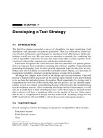
responds incorrectly. A two-dimensional plot called a schmoo is created that char-
acterizes behavior at a particular I/O pin relative to the parameter of interest. This is
illustrated in Figure 6.5, where the schmoo shows pass/fail regions at an output pin
OE
CLK
INBUS
OUTBUS
tphl
tplh
strobe_width
USING THE TESTER
295
Figure 6.5
A schmoo plot.
as a function of applied voltage. As the voltage decreases, the fail region increases.
If the specification for this IC calls for it to function correctly with a 21 ns clock
period at 4.0 V, it would just barely meet requirements. Schmoo plots can take on
many appearances; for example, the PASS region may be bounded on the right,
where the device again fails, yielding an elliptical shape.
When testers apply signals to ICs, they may be programmed to apply logic values
specified in pin memory for the entire clock period, or they may be programmed to
apply the specified value for part of a period and apply some other value for the
remainder of that period. Some commonly used formats include return-to-comple-
ment (sometimes called surround-by-complement, or XOR), return-to-zero, return-
to-one, return-to-high-impedance, and nonreturn. Figure 6.6 illustrates nonreturn
and return-to-one waveforms. Timing generator
TG
1
is programmed to go high from
25 ns to 30 ns. Timing generator
TG
2
is programmed to go high from 15 ns to 30 ns.
Figure 6.6
Nonreturn and return-to-one waveforms.
VCC
5.0
4.0
3.0
6.0
6.5
18 ns 19 ns 20 ns 21 ns 22 ns 23 ns 24 ns
FAIL
PASS
0 ns 50 ns 100 ns 150 ns 200 ns
TG
1
TG
2
PD
1
PW
1
PD
2
PW
2
296
AUTOMATIC TEST EQUIPMENT
Pin data
PD
1
and
PD
2
are identical; a logic 1 in pin memory is followed by a
logic 0, another 1, and then a 0. However, because the timing generators are differ-
ent and the waveform formats chosen are different, the resulting pin waveforms
PW
1
and
PW
2
are very different. When
PW
1
goes low, it remains low for 50 ns. When
PW
2
goes low, it remains low for 22.5 ns. The timing generators determine when the
signal changes, but the formatter determines its duration.
As mentioned earlier, complex, high-speed funcional testers are used to test ICs
and PCBs to ensure that they operate correctly. But these testers are also being used
to characterize new devices. During design, simulators and other electronic design
automation (EDA) tools are used at great length to predict how a new design will
work, once it is fabricated. However, predicting the behavior of a new technology,
always a difficult task, is increasingly complicated by deep submicron effects that
were often ignored in earlier technologies.
10
Not only are cell libraries more difficult
to characterize, but estimating delay in the wiring between cells must take into
account three-dimensional effects that were previously ignored. Guard bands are
used to provide a margin of safety during design, to increase the likelihood that the
device will operate correctly at its specified clock period. Nevertheless, it is becom-
ing increasingly important to measure critical parameters at speed on a tester to
ensure that they respond correctly.
In addition to verifying that a device operates correctly at its specified clock
speed, the tester can be used to determine its maximum operating frequency, as well
as to generate schmoo plots in order to determine how far the voltage can be
dropped before the device fails. Even when the device works correctly at rated
speed, the effects of altering clock speed and voltages on noise and crosstalk are dif-
ficult to predict with EDA tools.
The engineering test station is targeted to the design engineer. Its design goal is
flexibility, in order to allow easy setup of tests, quick change of test parameters, and
easy debug. A device can be characterized and debugged on the station, and when
the designers are satisfied that the device is working correctly, test information accu-
mulated during this phase is passed on to production, where the priority shifts to
maximizing throughput.
One of the parameters that is normally measured on a new device is propagation
time. The specification sheet may call for a signal change to occur at an output pin 8
ns after an active clock edge. The output pin may be schmoo’ed in order to deter-
mine whether it meets the 8 ns propagation time as well as to determine the margin
of error at that pin. After all of the pins are plotted, there is a good database for
determining which, if any, pins may represent problems during production.
When characterizing a device on an engineering test station, what happens if the
device fails to respond correctly at its intended frequency? The first thing that can
be done is to alter the clock frequency. Perhaps the device will operate correctly at a
slower frequency. If the device fails to operate correctly at any frequency, then it is
logical to assume that there is either a physical failure that occurred during the man-
ufacturing process or a design error. If several parts are available and if all of them
fail in an identical fashion, then the logical assumption is that there is a design error
that occurred during either the logic design process or the physical design process.
USING THE TESTER
297
Figure 6.7 Stretch-and-shrink test.
This will require that someone familiar with the logic investigate the response pat-
terns applied by the tester and determine where the defect is most likely to have
occurred. At some point it may be necessary to enlist the support of an E-Beam
prober to shed more light on the problem (cf. Section 6.5).
But, what happens if the device fails when running at its design frequency, but
manages to operate successfully when the clock frequency is lowered? In this case it
would be useful to know when the circuit first responds with incorrect results. This
can be done by using a stretch-and-shrink approach.
11
In this mode of operation, all
but one of the test vectors are operated at the slower clock period where the circuit
operates correctly. The first time through the vectors, the clock period for the first
vector is set to the intended design clock period. If the test passes, then the second
vector clock cycle is shrunk and the test is repeated. This is continued until eventu-
ally the test program fails. This is illustrated in Figure 6.7, where DataOut is cross-
hatched. This response may have been induced many vectors earlier by a fault that
caused some register or latch to assume an incorrect value.
With a short period on a single preceding vector, and given that the device
worked correctly when all the clock periods were applied at normal duration, there
is a high likelihood that the incorrect response occurred on the vector with the
shrunken cycle. Recall from Chapter 2, where simulation was discussed, that typi-
cally only a small percentage of elements in a circuit exhibit logic activity on any
given vector. So, knowing on which vector the error occurred can significantly
reduce the scope of the search for the problem. In fact, this knowledge, along with
information obtained from timing analysis (cf. Chapter 7), can often narrow the
search down to just a few critical signal paths. At that point an E-beam can help to
further isolate the problem or confirm suspicions as to what path is causing the fail-
ure. Armed with this knowledge, the logic designer can approach the redesign effort
with greater confidence that the next iteration will be successful.
The stretch-and-shrink test in Figure 6.7 is referred to as the ripple technique.
Other approaches can also be employed. In the domino technique, if the first n test
runs are successful, then the clock period for all of those vectors is held at the
Normal Shrink Normal Normal
Clock
DataIn
DataOut
Failed response
298
AUTOMATIC TEST EQUIPMENT
shrunken value. It might also be effective to use a variation on a binary search
wherein half of the vectors up to the point of failure are run at a shortened clock
period in order to expedite the debug process. It is also possible to reverse the entire
process, shortening all the clock cycles and then lengthening one or more on each
run until the test passes.
The engineering teststation is a powerful tool for characterizing and debugging
new designs. It can also be quite useful when it comes time to redesign the product.
Existing production units of a device can be evaluated to determine how much mar-
gin exists between the specified operating frequency and the target frequency in a
redesigned part. The stretch-and-shrink technique can be used to find those vectors
where the device begins to fail. That information can be used to help calibrate infor-
mation obtained from EDA tools. Conservative design rules may have resulted in a
device that is being operated far below the maximum frequency at which it is capa-
ble of operating.
A successful program for characterizing devices on an engineering workstation
requires stimuli that exercise all of the critical paths inside the device, as well as for-
matting capabilities in order to measure when signals appear at the output pins.
These are part of an AC test strategy. But a device that is plugged into a PCB affects
its environment. It may place an excessive load on other devices such that they are
unable to drive it, or it may have insufficient drive to control other devices. To guard
against this possibility, it is necessary to perform DC tests.
The DC test consists of forcing a voltage and measuring current, or forcing cur-
rent and measuring voltage. This is usually accomplished with the aid of a paramet-
ric measurement unit (PMU). It can be mechanically switched to replace a driver or
detector that is connected to a pin during normal production test operation. The
PMU can force a very precise voltage and measure the resulting current flow, or
force a very precise current and measure the resulting voltage. Measurements per-
formed during DC test include power consumption, opens and shorts, input and out-
put leakage, input and output load, and leakage.
12
When characterizing a device, it is necessary to put the device into a state that
permits the desired measurements to be made. A functional program may be run
until arriving at a desired output state. Then the measurement is taken. Alternatively,
a logic designer or test engineer may write a program whose sole purpose is to drive
the circuit into the desired state. For an output leakage test, it is necessary to put the
circuit into a state in which the outputs are tri-stated, then measure I
OZ
, the current at
an output when it is in the off-state.
Leakage current I
IL
is measured by forcing a low-level voltage onto an input by
means of the PMU and measuring the current. In similar fashion, leakage current I
IH
is measured by forcing a high-level voltage onto an input while measuring the cur-
rent. The high-level output voltage V
OH
is that voltage which, according to the prod-
uct specification, corresponds to a high level at the output. V
OL
corresponds to a low
level at the output. V
OH
is measured by driving the device to a state in which the pin
being measured is on, or high, while V
OL
is measured when the pin is low. Values for
these parameters are determined such that the outputs can drive several inputs or
loads with adequate noise margin. Guardbands may be established in order to ensure