Buckling analysis of eccentrically stiffened functionally graded circular cylindrical thin shells under mechanical load
Bạn đang xem bản rút gọn của tài liệu. Xem và tải ngay bản đầy đủ của tài liệu tại đây (384.94 KB, 18 trang )
<span class='text_page_counter'>(1)</span><div class='page_container' data-page=1>
55
Buckling analysis of eccentrically stiffened functionally
graded circular cylindrical thin shells under mechanical load
Nguyen Thi Phuong
1,*, Dao Huy Bich
2<i>1<sub>University of Transport Technology, 54 Trieu Khuc, Thanh Xuan, Hanoi, Vietnam </sub></i>
<i>2</i>
<i>Vietnam National University, Hanoi, 144 Xuan Thuy, Cau Giay, Hanoi, Vietnam </i>
Received 03 May 2013,
Revised 24 June 2013; Accepted 30 June 2013
<b>Abstract: An analytical approach is presented to investigate the linear buckling of eccentrically </b>
stiffened functionally graded thin circular cylindrical shells subjected to axial compression,
external pressure and tosional load. Based on the classical thin shell theory and the smeared
stiffeners technique, the governing equations of buckling of eccentrically stiffened functionally
graded circular cylindrical shells are derived. The functionally graded cylindrical shells with
simply supported edges are reinforced by ring and stringer stiffeners system on internal and (or)
external surface. The resulting equations in the case of compressive and pressive loads are solve
directly, while in the case of torsional load is solved by the Galerkin procedure to obtain the
explicit expression of static critical buckling load. The obtained results show the effects of
stiffeners and input factors on the buckling behavior of these structures.
<i>Keywords: </i>Functionally graded material; Cylindrical shells; Stiffeners; Buckling loads; Axial
compression; External pressure; Tosional load.
<b>1. Introduction</b>∗∗∗∗
The static and dynamic behavior of FGM cylindrical shell attracts special attention of a lot of
authours in the world.
In static analysis of FGM cylindrical shells, many studies have been focused on the buckling and
postbuckling of shells under mechanic and thermal loading. Shen [1] presented the nonlinear
postbuckling of perfect and imperfect FGM cylindrical thin shells in thermal environments under
lateral pressure by using the classical shell theory with the geometrical nonlinearity in von Karman–
Donnell sense. By using higher order shear deformation theory; this author [2] continued to investigate
the postbuckling of FGM hybrid cylindrical shells in thermal environments under axial loading. Bahtui
and Eslami [3] investigated the coupled thermo-elasticity of FGM cylindrical shells. Huang and Han
[4-7] studied the buckling and postbuckling of un-stiffened FGM cylindrical shells under axial
_______
∗
</div>
<span class='text_page_counter'>(2)</span><div class='page_container' data-page=2>
compression, radial pressure and combined axial compression and radial pressure based on the
Donnell shell theory and the nonlinear strain-displacement relations of large deformation. The
postbuckling of shear deformable FGM cylindrical shells surrounded by an elastic medium was
studied by Shen [8]. Sofiyev [9] analyzed the buckling of FGM circular shells under combined loads
<b>and resting on the Pasternak type elastic foundation. Zozulya and Zhang [10] studied the behavior of </b>
functionally graded axisymmetric cylindrical shells based on the high order theory.
For dynamic analysis of FGM cylindrical shells, Ng et al. [11] and Darabi et al. [12] presented
respectively linear and nonlinear parametric resonance analyses for un-stiffened FGM cylindrical
shells. Three-dimensional vibration analysis of fluid-filled orthotropic FGM cylindrical shells was
investigated by Chen et al. [13]. Sofiyev and Schnack [14] and Sofiyev [15] obtained critical
parameters for un-stiffened cylindrical thin shells under linearly increasing dynamic torsional loading
and under a periodic axial impulsive loading by using the Galerkin technique together with Ritz type
variation method. Shariyat [16] and [17] investigated the nonlinear dynamic buckling problems of
axially and laterally preloaded FGM cylindrical shells under transient thermal shocks and dynamic
buckling analysis for un-stiffened FGM cylindrical shells under complex combinations of thermo–
electro-mechanical loads. Geometrical imperfection effects were also included in his research. Li et al.
[18] studied the free vibration of three-layer circular cylindrical shells with functionally graded middle
layer. Huang and Han [19] presented the nonlinear dynamic buckling problems of un-stiffened
functionally graded cylindrical shells subjected to time-dependent axial load by using the Budiansky–
Roth dynamic buckling criterion [20]. Various effects of the inhomogeneous parameter, loading speed,
dimension parameters; environmental temperature rise and initial geometrical imperfection on
<b>nonlinear dynamic buckling were discussed. Shariyat [21] analyzed the nonlinear transient stress and </b>
wave propagation analyses of the FGM thick cylinders, employing a unified generalized
thermo-elasticity theory
Recently, idea of eccentrically stiffened FGM structures has been proposed by Najafizadeh et al.
[22] and Bich et al. [23 and 24]. Najafizadeh et al. [22] have studied linear static buckling of FGM
axially loaded cylindrical shell reinforced by ring and stringer FGM stiffeners. In order to provide
material continuity and easily to manufacture, the FGM shells are reinforced by an eccentrically
homogeneous stiffener system; Bich et al. have investigated the nonlinear static postbuckling of
functionally graded plates and shallow shells [23] and nonlinear dynamic buckling of functionally
graded cylindrical panels [24].
This paper presented an analytical approach to investigated the linear buckling of eccentrically
stiffened FGM cylindrical shell subjected to axial compression, external pressure and tosional load.
Effects of stiffeners and input factors on the static buckling behavior of these structures are also
considered.
<b>2. Governing equations </b>
<i>2.1. Functionally graded material (FGM) </i>
</div>
<span class='text_page_counter'>(3)</span><div class='page_container' data-page=3>
a mixture of ceramic and metal, or a combination of different materials. A such mixture of ceramic
and metal with a continuously varying volume fraction can be manufactured. Especially FGM thin –
walled structures with ceramic in inner surface and metal in outer surface are widely used in practice.
Assume that the modulus of elasticity E changes in the thickness direction z, while the Poisson ratio
ν
is assumed to be constant. Denote V<sub>m</sub> and V<sub>c</sub> being volume – fractions of metal and ceramicphases respectively, which are related by V<sub>m</sub>+V<sub>c</sub> =1 and V<sub>c</sub> is expressed as 2
2
( )
k
c
z h
V z
h
+
=
,
where h is the thickness of thin-walled structure,
k
is the volume – fraction exponent (k ≥ ). Then 0the elasticity modulus and the Poisson ratio of functionally graded material can be evaluated as
following
(
)
22
k
m m c c m c m
z h
E z E V E V E E E
h
+
= + = + −
( ) ,
z const
ν( )= ν = .
The values with subscripts m and
c
belong to metal and ceramic respectively.<i>2.2. Eccentrically stiffened functionally graded cylindrical shells. </i>
<i>Consider a cylindrical shell of thickness h, length L, radius R and reinforced by internal and </i>
<i>external stiffeners. The shell is referred to a coordinate system (x, y, z), in which x and y are in the </i>
<i>axial and circumferential directions of the shell and z is in the direction of the inward normal to the </i>
middle surface.
In the present study, the classical shell theory and the Lekhnitsky smeared stiffeners technique are
used to obtain the equilibrium and compatibility equations as well as expressions of buckling loads
and nonlinear load – deflection curves of eccentrically stiffened FGM cylindrical shells.
</div>
<span class='text_page_counter'>(4)</span><div class='page_container' data-page=4>
The strains across the shell thickness at a distance z from the mid-surface are
0 0 0
2
x x z x y y z y xy xy z xy
ε = ε − χ , ε = ε − χ , γ = γ − χ , (1)
where
ε
0<sub>x</sub> and ε0<sub>y</sub> are normal strains, γ0<sub>xy</sub> is the shear strain at the middle surface of the shell andij
χ are the curvatures.
According to the classical shell theory the strains at the middle surface and curvatures are related
to the displacement components
u v w
,
,
in thex y z
,
,
coordinate directions as [25].2 2
0
2
2 <sub>2</sub>
0
2
2
0
1
2
1 1
2
x x
x y
xy xy
u w w
, ,
x x x
v w w
w , ,
y R y y
u v w w w
, .
y x x y x y
ε χ
ε χ
γ χ
∂ ∂ ∂
= + <sub></sub> <sub></sub> =
∂ ∂ ∂
∂ ∂ ∂
= − + =
∂ ∂ ∂
∂ ∂ ∂ ∂ ∂
= + + =
∂ ∂ ∂ ∂ ∂ ∂
(2)
From Eqs.(2) the strain must be satify in the deformation compatibility equation
2 0 2 0
2 0 2
2 2 2
1
y xy
x w
x y R
y x x
∂ ε ∂ γ
∂ ε ∂
+ − = −
∂ ∂
∂ ∂ ∂ . (3)
The constitutive stress – strain equations by Hooke law for the shell material are omitted here for
brevity. The contribution of stiffeners can be accounted for using the Lekhnitsky smeared stiffeners
technique. Then integrating the stress – strain equations and their moments through the thickness of
the shell, the expressions for force and moment resultants of an eccentrically stiffened FGM
cylindrical shell are obtained.
(
)
(
)
0 0
11 12 11 12
0 0
12 22 12 22
0
66 2 66
s
x x y s x y
s
r
y x y x r y
r
xy xy xy
EA
N A A B C B
s
EA
N A A B B C
s
N A B
= + ε + ε − + χ − χ
= ε + + ε − χ − + χ
= γ − χ
,
,
,
(4)
(
)
(
)
0 0
11 12 11 12
0 0
12 22 12 22
0
66 2 66
s
x s x y x y
s
r
y x r y x y
r
xy xy xy
EI
M B C B D D
s
EI
M B B C D D
s
M B D
</div>
<span class='text_page_counter'>(5)</span><div class='page_container' data-page=5>
where A<sub>ij</sub>, B<sub>ij</sub>, D<sub>ij</sub>
(
i j, =1 2 6, ,)
are extensional, coupling and bending stiffenesses of the shellwithout stiffeners.
(
)
(
)
(
)
1 1 1
11 22 <sub>2</sub> 12 <sub>2</sub> 66
2 2 2
11 22 2 12 2 66
3 3 3
11 22 2 12 2 66
2 1
1 1
2 1
1 1
2 1
1 1
ν
= = = =
+ ν
− ν − ν
ν
= = = =
+ ν
− ν − ν
ν
= = = =
+ ν
− ν − ν
, , ,
, , ,
, , ,
E E E
A A A A
E E E
B B B B
E E E
D D D D
(6)
with
(
)
(
)(
)
(
)
2
1 2
3
3
1 2 1 2
1 1 1
12 3 2 4 4
, ,
,
c m
c m
m
m
c m
E E kh
E E
E E h E
k k k
E
E E E h
k k k
−
−
=<sub></sub> + <sub></sub> =
+ + +
=<sub></sub> + − <sub></sub> − + <sub></sub><sub></sub>
+ + +
and
= ± s s, = ± r r.
s r
s r
EA z EA z
C C
s s (7)
In above relations (4), (5) and (7) E is the elasticity modulus of the corresponding stiffener which
is assumed identical for both types of stiffeners. The spacings of the longitudinal and transversal
stiffeners are denoted by s<sub>1</sub> and s<sub>2</sub> respectively. The quantities A<sub>s</sub>, A<sub>r</sub> are the cross section areas of
the stiffeners and I<sub>s</sub>, I<sub>r</sub>, z<sub>s</sub>, z<sub>r</sub> are the second moments of cross section areas and eccentricities of
the stiffeners with respect to the middle surface of the shell respectively. The sign plus or minus of
s r
C
,
C
dependent on internal or external stiffeners.<i><b>Important remark. In order to provide continuity between the shell and stiffeners, thus stiffeners </b></i>
are made of full metal if putting them at the metal – rich side of the shell and conversely full ceramic
stiffeners at the ceramic-rich side of the shell, consequently E=E<sub>m</sub> for full metal stiffeners and
c
E =E for full ceramic ones.
The nonlinear equilibrium equations of a cylindrical shell based on the classical shell theory are
given by
2 2
2 2 2 2
2 2 2 2
0
0
2 2
xy
x
xy y
xy y y
x
x xy y
N
N
x y
N N
x y
M M N
M w w w
N N N q
x y x y R
x y x y
</div>
<span class='text_page_counter'>(6)</span><div class='page_container' data-page=6>
Stability equations of eccentrically stiffened functionally graded shell may be established by the
adjacent equilibrium criterion. It is assumed that equilibrium state of the eccentrically stiffened
functionally graded shell under applied load is presented by displacement component u<sub>0</sub>, v<sub>0</sub>, w<sub>0</sub>.
The state of adjacent equilibrium differs that of stable eauilibrium by u<sub>1</sub>, v<sub>1</sub>, and w ,<sub>1</sub> and the total
displacement component of a neighboring configuration are
0 1 0 1 0 1
u
=
u
+
u
,
v
=
v
+
v
,
w
=
w
+
w
.
(9)Similar, the force and moment resultants of a neighboring state are represented by
0 1 0 1 0 1
x x x y y y xy xy xy
N =N +N , N =N +N , N =N +N ,
0 1 0 1 0 1
= + , = + , = + ,
x x x y y y xy xy xy
M M M M M M M M M
(10)
<i>where terms 0 subscripts correspond to the </i> u<sub>0</sub>, v<sub>0</sub>, w<sub>0</sub><i> displacements and those with 1 </i>
subscription represents the portions of the increments of force and moment resultants that are linear in
1 1 1
u, v, w.Subsequently, introduction of Eqs. (9) and Eq.(10) into (8) and subtracting from the
resulting equations term relating to stable equilibrium state, neglecting nonlinear term in u<sub>1</sub>, v<sub>1</sub>, w<sub>1</sub>
or their counterparts in the form of N1<sub>x</sub>, N1<sub>y</sub>, N1<sub>xy</sub>, etc… and prebuckling rotations yeild stability
equations.
1
1
1 1
2 1 2 1 1
2 1 2 2 2
0 0 0
2 2 2 2
0
0
2 2 0
xy
x
xy y
xy y y
x
x xy y
N
N
x y
N N
x y
M M N
M w w w
N N N
x y x y R
x y x y
∂
∂
+ =
∂ ∂
∂ ∂
+ =
∂ ∂
∂ ∂
∂ ∂ ∂ ∂
+ + + + + + =
∂ ∂ ∂ ∂
∂ ∂ ∂ ∂
,
,
.
(11)
Considering the first two of Eqs.(11), a stress function may be defined as
2 2 2
1 1 1
2 2
∂ ϕ ∂ ϕ ∂ ϕ
= = = −
∂ ∂
∂ , ∂ , .
x y xy
N N N
x y
y x (12)
For using later, the reverse relations are obtained from Eqs.(4)
0 1 1
22 12 11 12
0 1 1
11 12 21 22
0
66 2 66
* * * *
x x y x y
* * * *
y y x x y
* *
xy xy
A N A N B B ,
A N A N B B ,
A B ,
ε
χ
χ
ε
χ
χ
γ
χ
= − + +
= − + +
= +
</div>
<span class='text_page_counter'>(7)</span><div class='page_container' data-page=7>
where
(
)
(
)
(
)
(
)
1 2 12
11 11 22 22 12 66
1 2 66
2
1 2
11 22 12
1 2
11 22 11 1 12 12 22 11 22 2 12 12
12 22 12 12 22 2 21 11 12 12 11 1
1 1 1
* * * *
* * * * * *
* * * * * *
, , , ,
;
, ,
, ,
EA EA A
A A A A A A
s s A
EA EA
A A A
s s
B A B C A B B A B C A B
B A B A B C B A B A B C
= + = + = =
∆ ∆ ∆
∆ = + + −
= + − = + −
= − + = − + 66
66
66
*
.
B
B
A
=
Substituting Eqs. (13) into Eqs.(5) yields
1 1 1
11 21 11 12
1 1 1
12 22 21 22
1 1
66 2 66
x x y x y
y x y x y
xy xy xy
M B N B N D D
M B N B N D D
M B N D
= + − χ − χ
= + − χ − χ
= − χ
* * * *
* * * *
* *
,
,
,
(14)
where
(
)
(
)
(
)
(
)
1
11 11 11 1 11 12 21
1
2
22 22 12 12 22 2 22
2
12 12 11 1 12 12 22
21 12 12 11 22 2 21
66 66 66 66
* * *
* * *
* * *
* * *
* *
,
,
,
,
.
EI
D D B C B B B
s
EI
D D B B B C B
s
D D B C B B B
D D B B B C B
D D B B
= + − + −
= + − − +
= − + −
= − − +
= −
The substitution of Eqs.(13) into the compatibility Eqs.(3) and Eqs.(14) into the third of Eqs.(11),
taking into account expressions (2) and (12), yields a system of equations
(
)
(
)
4
4 4 4
1
11 4 66 12 2 2 22 4 21 4
4 4 2
1 1 1
11 22 66 2 2 12 4 2
2
1
2 0
w
A A A A B
x x y y x
w w w
B B B B
R
x y y x
∂
∂ ϕ ∂ ϕ ∂ ϕ
+ − + + +
∂ ∂ ∂ ∂ ∂
∂ ∂ ∂
+ + − + + =
∂ ∂ ∂ ∂
* * * * *
* * * * <sub>,</sub> (15)
(
)
(
)
4 4 4 4
1 1 1
11 4 12 21 66 2 2 22 4 21 4
2 2 2
4 4 2
0 1 0 1 0 1
11 22 66 2 2 12 4 2 2 2
4
1
2 <sub>x</sub> 2 <sub>xy</sub> <sub>y</sub> 0
w w w
D D D D D B
x x y y x
w w w
B B B B N N N
R x y
x y y x x y
</div>
<span class='text_page_counter'>(8)</span><div class='page_container' data-page=8>
Eqs.(15) and (16) are the basic equations used to investigate the stability of eccentrically stiffened
functionally graded cylindrical shells. They are linear equations in terms of two dependent unknowns
1
w and ϕ.
<i>2.3. Buckling analysis of eccentrically stiffened functionally graded cylindrical shells subjected to </i>
<i>axial compressive load and external pressure. </i>
In the present study, the eccentrically stiffened FGM shell to be free simply supported at all edges
<i>and subjected to axial compression load p uniformly distributed on the two end edges of the shell and </i>
<i>external pressure q uniform distributed on the surface . By solving the membrane form of equilibrium </i>
eqauations, prebuckling force resultants are determined
0 0 0 <sub>0</sub>
x y xy
N = −ph, N = −qR, N = . (17)
The boundary conditions considered in the current study are
2
1 1
1
1 0 2 0 x 0 xy 0 <i>a</i> 0
w
w , , N , N , t x ; L.
x
∂
= = = = =
∂ (18)
<i>where L are the lengths of in-plane edges of the cylindrical shell. </i>
The mentioned conditions (18) can be satisfied if the buckling mode shape is represented by
1 mn
m n
m x ny
w W sin sin ,
L R
π
=
∑∑
<sub>(19) </sub>where W<sub>mn</sub><i> is a maximum deflection, m is the number of axis half waves and n is the number of </i>
circumferential waves. Substituting Eq.(19) into Eq.(15) and solving obtained equation for unknown
ϕ
leads tomn
m n
m x ny
sin sin
L R
π
ϕ=
∑∑
φ <sub>(20) </sub>where
(
)
(
)
4 4 2 2 2 2 4 4 2 2 2
21 11 22 66 12
4 4 2 2 2 2 4 4
11 66 12 22
2
2
π π λ λ π λ
φ
π π λ λ
<sub>+</sub> <sub>+</sub> <sub>−</sub> <sub>+</sub> <sub>−</sub>
= −
+ − +
* * * * *
mn <sub>*</sub> <sub>*</sub> <sub>*</sub> <sub>*</sub> mn
B m B B B m n B n Rm
W .
A m A A m n A n (21)
Introduction of expressions (19) and (20) into Eqs.(16) leads to
(
)
2
0 2 2 0 2 2 2 <sub>0</sub>
<sub>π</sub>
+ + π + λ =
∑∑
x y mnsin sin ,m n
B m x ny
D N m N n L W
A L R (22)
</div>
<span class='text_page_counter'>(9)</span><div class='page_container' data-page=9>
(
)
(
)
(
)
4 4 2 2 2 2 4 4
11 66 12 22
4 4 2 2 2 2 4 4 2 2 2
21 11 22 66 12
4 4 2 2 2 2 4 4
11 12 21 66 22
2
2
4
= π + − π λ + λ λ =
= π + + − π λ + λ − π λ
= π + + + π λ + λ
* * * *
* * * * *
* * * * *
, ,
,
.
L
A A m A A m n A n
R
B B m B B B m n B n Rm
D D m D D D m n D n
<i>Eq.(22) satisfies for all x, y if </i>
(
)
2
0 2 2 0 2 2 2 <sub>0</sub>
+B + <sub>x</sub> π + <sub>y</sub> λ = .
D N m N n L
A (23)
Now investigate the linear buckling of reinforced FGM cylindrical shells in some cases of active
load.
<i>Consider the cylindrical shell subjected the axial compression (q = 0), Eq. (23) becomes: </i>
2
2 2 2 <sub>0</sub>
+B − π =
D phm L
A (24)
Introduction parameters:
3
= D, =B, = . ,
D B A A h
h
h (25)
from Eq.(24) the compressive buckling load can be obtained
2 2
2 2 2
= <sub></sub> + <sub></sub>
π .
h B
p D
A
m L (26)
The critical axial compression load of eccentrically stiffened FGM cylindrical shell is determined
by condition p<sub>cr</sub> = minp<i> vs. (m, n). </i>
<i>Consider the cylindrical shell subjected the external pressure (p = 0), the Eq. (23) becomes: </i>
2
2 2 2 <sub>0</sub>
+B − λ =
D qRn L
A
The pressure buckling load can be determined :
2 2
2 2 2 3
2 4
1 1
= <sub></sub> + <sub></sub>= <sub></sub> + <sub></sub>
λ
λ
B B
q D D
A A
Rn L <sub>R</sub>
n
h
(27)
</div>
<span class='text_page_counter'>(10)</span><div class='page_container' data-page=10>
<i>2.4. Buckling analysis of eccentrically stiffened functionally graded cylindrical shells subjected to </i>
<i>torsional load </i>
The eccentrically stiffened FGM shell to be free simply supported at all edges and subjected to
torsional load τ. By solving the membrane form of equilibrium equations, prebuckling force
resultants are determined
0 0 0
2
0 0
2
s
x y xy
M
N N N h
R
= = = τ =
π
, , . (28)
The buckling mode shape is represented in the form
(
)
1
γ
π −
= x n y x
w W sin sin ,
L R (29)
where W is a maximum deflection. At the edges x =0, x =L the simple supported condition of
shell is satisfied. The deflection is vanished along the straight lines y= γxrepeated n times at each
shell cross-section, where γ is tangent of slope angle between these lines and the shell genetic.
Substituting (29) into Eq.(15) and solving obtained equation for unknown
ϕ
leads to(
)
(
)
1 2
n y x n y x
x x
sin sin cos cos ,
L R L R
γ γ
π π
ϕ φ= − +φ − (30)
where
(
)
1 <sub>2</sub> <sub>2</sub> 2 <sub>2</sub> <sub>2</sub>
4 2 2 4 2 2 2 4
11 6 66 2 12 22
φ φ
π π γ γ π γ
− −
= =
− −
<sub></sub> <sub></sub> <sub></sub> <sub> </sub> <sub></sub> <sub></sub> <sub></sub> <sub></sub> <sub></sub> <sub></sub> <sub></sub> <sub></sub> <sub></sub> <sub></sub> <sub></sub>
= + + + − + +
* * * *
MH NK MK NH
W , W ,
H K K H
n n n n n
K A A A A ,
L L R R L R R R
(
)
(
)
3 3 2
11 66 12
4 2 2 4
21
2 2 2
11 22 66 12
4 2 2
6
2
π γ π γ π γ
π π γ γ
π γ
<sub></sub> <sub></sub> <sub></sub> <sub></sub> <sub></sub> <sub></sub> <sub></sub>
= + + −
<sub></sub><sub></sub> <sub></sub> <sub></sub> <sub> </sub> <sub></sub> <sub></sub> <sub></sub> <sub></sub>
= −<sub></sub> + + +
<sub></sub> <sub></sub> <sub></sub> <sub></sub> <sub></sub> <sub></sub>
+ + − + +
* * *
*
* * * *
n n n n
H A A A ,
L R L R L R R
n n
M B
L L R R
n n n
B B B B
L R R R
4 2 2
1 π γ
<sub></sub>
− +
<sub></sub>
<sub></sub><sub></sub> <sub></sub><sub></sub>
n
,
R L R
(
)
3 3 2
21 11 22 66
1
4 π γ π γ 2 2 π γ 2 π γ
<sub></sub><sub></sub> <sub></sub> <sub></sub> <sub></sub> <sub></sub> <sub></sub> <sub></sub> <sub></sub>
= −<sub></sub> + + + − − <sub></sub>
* n n * * * n n n
N B B B B ,
L R L R L R R R L R
</div>
<span class='text_page_counter'>(11)</span><div class='page_container' data-page=11>
(
)
(
)
0
1 1 2
0
2 1 2
2
2 0
γ
γ π
φ φ
γ
γ π
φ φ
−
+ + − +
−
+<sub></sub> + + − <sub></sub> =
xy
xy
n y x
n n x
D W M N N W sin sin
R R L R
n y x
n n x
D W N M N W cos cos .
R R L R
(31)
where
(
)
(
)
4 2 2 4
1 11
2 2 2 4
12 21 66 22
3 3
2 11 12 21 66
6
4
4 2 4
π π γ γ
π γ
π γ π γ π γ
<sub></sub> <sub></sub> <sub></sub> <sub> </sub> <sub></sub> <sub></sub> <sub></sub>
= + + +
<sub></sub> <sub></sub> <sub></sub> <sub></sub> <sub></sub> <sub></sub> <sub></sub> <sub></sub>
+ + + + +
<sub></sub> <sub></sub> <sub></sub> <sub></sub> <sub></sub>
= + + + +
*
* * * *
* * * *
n n
D D
L L R R
n n n
D D D D ,
L R R R
n n n
D D D D D
L R L R L R
2
n
.
R
Application of Garlerkin method for the Eq.(31) yields
2
0
2
2 0
<sub></sub> <sub>γ</sub> <sub>π</sub> <sub></sub>
+ − + =
. . n n <sub>xy</sub> ,
U P V Q P Q N W
L R
R (32)
where
(
)
1 1 2
2 1 2
2 2 2
2 2
2 2 2 2 2 2
3
2 2
2 2 2 2 2
1 4 2 2
2 4
4
4 2 2
4
4
<i>W</i>
<i>W</i>
φ φ
φ φ
γ π γ π γ
π
π γ γ
π π γ π γ
π γ
= + +
= + +
<sub></sub> <sub></sub>
= − + +
−
= +
−
U D M N ,
V D N M ,
R L R n n L n n L
P L sin sin sin sin ,
R R R R
R n L n
R L n n L n n L
Q sin sin sin sin .
R R R R
n R n L
By subtitution N<sub>xy</sub>0 = τ<b>h into Eq.(32), the buckling torsional load is obtained as </b>
2
2
2
2
2
τ π τ
γ π
+
= =
+
s
U .P V .Q
, M R h .
n n
h P Q
L R
R
(33)
The critical torsion load of eccentrically stiffened FGM cylindrical shell are determined by
condition τ<sub>cr</sub> =<i>min vs. </i>τ
(
n, γ)
.<b>3. Numerical examples </b>
</div>
<span class='text_page_counter'>(12)</span><div class='page_container' data-page=12>
mechanical load are analyzed. The results shown in the Table 1- 4. As can be seen, the very good
agreements are obtained.
Table 1. Comparison of the present critical buckling load p<sub>cr</sub> (MPa) with theoritical results
<b>reported by Huang and Han [19]</b>
(
0)
0 300 2
T = K L R, =
Huang and Han
(σ<sub>scr</sub> = σ<sub>dcr</sub> τ<sub>cr</sub>) Present Difference (%)
Critical load versus k
500
R h =
k =0.2 189.262 (2, 11) 189.324 (2, 11) 0.033
k= 1.0 164.352 (2, 11) 164.386 (2, 11) 0.021
k= 5.0 144.471 (2, 11) 144.504 (2, 11) 0.023
Critical load versus R/h
k=0.2
400
R h = 236.578 (5, 15) 236.464 (5, 15) -0.048
600
R h = 157.984 (3, 14) 158.022 (3, 14) 0.024
800
R h = 118.849 (2, 12) 118.898 (2, 12) 0.041
Table 2. Comparisons of critical buckling load of internal stiffened isotropic cylindrical
shells under external pressure (Psi)
Barush and Singer [27] Shen [28] Present
Un-stiffened 102 100.7 (1, 4) 103.327 (1, 4)
Stringer stiffened 103 102.2 (1, 4) 104.494 (1, 4)
Ring stiffened 370 368.3 (1, 3) 379.694 (1, 3)
Orthogonal stiffened 377 374.1 (1, 3) 387.192 (1, 3)
<b>Table 3. Comparisons of critical torsion load </b>
τ
<sub>cr</sub> (psi) of un-stiffened isotropic cylindrical shell (<i>E</i>
=
29 10
×
6Psi, <i>L</i>=19,85 in, <i>R</i>= in, 3 <i>h</i>=0, 0075 in, ν =0,3)
Eksrom [30]
<b>Experiment </b> Theory Shen [29] Present
<b>4800 </b> 5500 4997 (1, 3) 4831.57 (7, 0.14)
<b>Table 4: Comparisons of critical buckling load per unit length </b>p<sub>cr</sub> =p .h<sub>cr</sub>
(
106N m)
of stiffenedhomogeneous cylindrical shell under axial compression
Present Brush and Almorth [25] Difference
( )
%<i>50 rings, 50 stringers, L=1m, R=0.5m, </i> 9
(
2)
70 10
E= × N m ,
ν
=0 3. , d<sub>r</sub> =d<sub>s</sub>=0 0025. m, h<sub>r</sub>=h<sub>s</sub>=0 01. m,Internal stiffeners
100
R h = 3.0725 (6, 7) 3.0906 (6, 7) 0.59
200
R h = 1.4147 (6, 7) 1.4328 (6, 7) 1.28
500
</div>
<span class='text_page_counter'>(13)</span><div class='page_container' data-page=13>
External stiffeners
100
R h = 3.9529 (9,3) 3.9551 (9, 2) 0.06
200
R h = 2.1410 (9, 4) 2.1369 (9,4) 0.28
500
R h = 1.2764 (6, 6) 1.2897 (6, 6) 1.04
To illustrate the proposed approach of eccentrically stiffened FGM cylindrical shells, the stiffened
and un-stiffened FGM cylindrical shells are made by the combination of materials consists of
Aluminum 10
7 10
m
E = ×= ×= ×= × N/m2 and Alumina 10
38 10
c
E ==== ×××× N/m2. The Poisson’s ratio ν is chosen to be
0.3 for simplicity. The height of stiffeners is equal to 0 005. m, its width 0 002. <i><b>m. The material </b></i>
<b>properties are </b> E<sub>s</sub> ====E<sub>c</sub> and E<sub>r</sub>====E<sub>c</sub> with internal stringer stiffeners and internal ring stiffeners;
s m
E ====E , E<sub>r</sub> ====E<sub>m</sub><b> with external stringer stiffeners and external ring stiffeners, respectively. The </b>
stiffener system includes 10 ring stiffeners and 10 stringer stiffeners distributed regularly in the axial
and circumferential directions, respectively.
<b>Table 5: Critical buckling load of stiffened FGM cylindrical shell under axial and pressure load </b>
(L R=2,h=0 002. m,d<sub>r</sub>=d<sub>s</sub>=0 002. m, h<sub>r</sub>=h<sub>s</sub>=0 005. m, n<sub>r</sub>=n<sub>s</sub>=10).
(
<i>a</i>)
cr
p GP q<sub>cr</sub>
(
MP<i>a</i>)
R h <i>k</i>
Un-stiffened External
stiffeners
Internal
stiffeners Un-stiffened
External
stiffeners
Internal
stiffeners
100
0.
2 1.936 (7, 9) 2.245 (10, 5) 2.740 (6, 7) 1.548 (1, 6) 2.658 (1, 6) 5.848 (1, 5)
1 1.249 (8, 9) 1.584 (10, 5) 1.961 (6, 7) 0.970 (1, 6) 2.064 (1, 5) 4.729 (1, 5)
5 0.746 (6, 9) 1.051 (9, 5) 1.280 (5, 6) 0.610 (1, 6) 1.561 (1, 5) 3.623 (1, 4)
10 0.640 (11, 2) 0.921 (9, 4) 1.120 (5, 6) 0.541 (1, 6) 1.420 (1, 5) 3.293 (1, 4)
200
0.
2 0.968 (8, 13) 1.047 (13, 10) 1.197 (10,11) 0.270 (1, 7) 0.364 (1, 7) 0.712 (1, 6)
1 0.625 (17, 2) 0.712 (14, 9) 0.837 (10,11) 0.170 (1, 7) 0.272 (1, 7) 0.559 (1, 6)
5 0.373 (4, 11) 0.454 (14, 8) 0.537 (9,10) 0.106 (1, 7) 0.203 (1, 6) 0.438 (1, 6)
10 0.320 (6, 12) 0.394 (13, 7) 0.471 (8, 9) 0.093 (1, 7) 0.182 (1, 6) 0.420 (1, 6)
300
0.
2 0.645 (15,14) 0.681 (17, 11) 0.753 (13,13) 0.097 (1, 8) 0.121 (1, 8) 0.211 (1, 7)
1 0.416 (16,14) 0.456 (17, 12) 0.517 (13,13) 0.060 (1, 8) 0.087 (1, 8) 0.164 (1, 7)
5 0.249 (17,11) 0.285 (16,11) 0.329 (11,12) 0.038 (1, 8) 0.062 (1, 7) 0.128 (1, 7)
10 0.213 (19, 4) 0.247 (16, 9) 0.287 (11,12) 0.034 (1, 8) 0.056 (1, 7) 0.121 (1, 6)
a
</div>
<span class='text_page_counter'>(14)</span><div class='page_container' data-page=14>
<b>Table 6: Critical buckling load </b>τ<sub>cr</sub>
(
GP<i>a</i>)
of stiffened FGM cylindrical shell under torsion load(L R=2,h=0 002. m ,dr=ds=0 002. m, hr=hs=0 005. m, nr=ns=10)
<i>R h </i> <i>k</i> Un-stiffened External stiffeners Internal stiffeners
100
0.2 0.548 (8, 0.367)b 0.784 (8, 0.646) 1.128 (7, 0.925)
1 0.348 (8, 0.349) 0.577 (8, 0.873) 0.825 (6, 1.047)
5 0.213 (8, 0.384) 0.407 (7, 0.873) 0.566 (6, 0.925)
10 0.186 (8, 0.401) 0.363 (7, 0.873) 0.516 (6, 0.908)
150
0.2 0.329 (9, 0.332) 0.434 (9, 0.436) 0.599 (8, 0.995)
1 0.209 (9, 0.314) 0.317 (9, 0.960) 0.436 (8, 0.995)
5 0.128 (9, 0.332) 0.216 (8, 1.117) 0.299 (7, 1.012)
10 0.112 (9, 0.349) 0.191 (8, 1.065) 0.269 (7, 0.960)
200
0.2 0.229 (10, 0.314) 0.288 (10, 0.384) 0.392 (9, 1.030)
1 0.146 (10, 0.297) 0.208 (10, 0.436) 0.280 (9, 1.030)
5 0.089 (10, 0.332) 0.141 (10, 0.873) 0.192 (8, 1.065)
10 0.078 (10, 0.349) 0.125 (10, 0.855) 0.172 (8, 0.995)
b
<i>The numbers in brackets indicate the buckling mode (n, </i>
γ
) .Critical buckling load of FGM cylindrical shell under axial compression, external pressure and
torsion load are considered in table 5 and 6. The results show that the critical buckling load of
<i>stiffened shells is larger than one of un-stiffened shells. Table 5 and 6 also show effects of R/h ratio </i>
<i>and k index to the critical buckling load of shells. Clearly, the critical buckling load of shell increases </i>
<i>when R/h ratio or k index decreases. It seems that, effect of stiffeners on the external pressure case is </i>
<i>the greatest than one of axial compression. Effects of stiffeners increase when R/h ratio or k index </i>
increases.
</div>
<span class='text_page_counter'>(15)</span><div class='page_container' data-page=15>
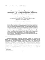
Fig.3. Effect of ratio R h on the buckling load of internal stiffened FGM cylindrical
shells under exteral pressure.
Fig.4. Effect of ratio R h on the buckling load of internal stiffened FGM cylindrical
shells under torsional load.
</div>
<span class='text_page_counter'>(16)</span><div class='page_container' data-page=16>
Fig.5. Effect of ratio L R on the buckling load of internal stiffened FGM cylindrical
shells under exteral pressure.
Fig.6. Effect of ratio L R on the buckling load of internal stiffened FGM cylindrical
shells under torsional load.
</div>
<span class='text_page_counter'>(17)</span><div class='page_container' data-page=17>
<b>5. Conclusion </b>
A formulation of governing equations of eccentrically stiffened functionally graded circular
cylindrical thin shells subjected to axial compression, external pressure and torsion load based upon
the classical shell theory and the smeared stiffeners technique is presented in this paper. By using the
Galerkin method the explicit expressions of buckling torsion load. The obtained results show that
stiffeners enhance the static stability and load-carrying capacity of FGM circular cylindrical shells.
<i>Effects of R/h ratio, L/R ratio and k index to the buckling curve and critical buckling load of shells </i>
were considered.
<b>Acknowledgements </b>
This research is funded by Vietnam National Foundation for Science and Technology
Development (NAFOSTED) under Grant number 107.01-2012.02.
<b>References </b>
[1] Shen HS. Postbuckling analysis of pressure-loaded functionally graded cylindrical shells in thermal
environments. Eng Struct 2003;25(4):487-97.
[2] Shen HS. Postbuckling of axially-loaded FGM hybrid cylindrical shells in thermal environments. Compos Sci
Technol 2005;65(11-12):1675–90.
[3] Bahtui A, Eslami MR. Coupled thermoelasticity of functionally graded cylindrical shells. Mech Res Commun
2007 ;34(1):1–18.
[4] Huang H, Han Q. Buckling of imperfect functionally graded cylindrical shells under axial compression. Eur J
Mech – A/Solids 2008;27(6):1026–36.
[5] Huang H, Han Q, Nonlinear elastic buckling and postbuckling of axially compressed functionally graded
cylindrical shells, Int J Mech Sci 2009;51(7):500-7.
[6] Huang H, Han Q. Nonlinear buckling and postbuckling of heated functionally graded cylindrical shells under
combined axial compression and radial pressure. Int J Non-Linear Mech 2009;44(2):209–18.
[7] Huang H, Han Q. Research on nonlinear postbuckling of FGM cylindrical shells under radial loads. Compos
Struct 2010;92(6):1352-7.
[8] Shen HS. Postbuckling of shear deformable FGM cylindrical shells surrounded by an elastic medium. Int J Mech
Sci 51(5) 2009: 372-83
[9] Sofiyev AH. Buckling analysis of FGM circular shells under combined loads and resting on the Pasternak type
elastic foundation. Mech Res Commun 2010;37( 6):539–44.
[10] Zozulya VV, Zhang Ch. A high order theory for functionally graded axisymmetric cylindrical shells. Int J Mech
Sci 2012;60(1):12-22.
[11] Ng TY, Lam KY, Liew KM, Reddy JN. Dynamic stability analysis of functionally graded cylindrical shells under
periodic axial loading. Int J Solids Struct 2001;38(8):1295-309.
[12] Darabi M, Darvizeh M, Darvizeh A. Non-linear analysis of dynamic stability for functionally graded cylindrical
shells under periodic axial loading. Compos Struct 2008;83(2):201–11.
[13] Chen WQ, Bian ZG, Ding HJ. Three-dimensional vibration analysis of fluid-filled orthotropic FGM cylindrical
shells. Int J Mech Sci 2004;46(1):159-71.
</div>
<span class='text_page_counter'>(18)</span><div class='page_container' data-page=18>
[15] Sofiyev AH. The stability of compositionally graded ceramic–metal cylindrical shells under aperiodic axial
impulsive loading. Compos Struct 2005;69(2):247–57.
[16] Shariyat M. Dynamic thermal buckling of suddenly heated temperature-dependent FGM cylindrical shells, under
combined axial compression and external pressure. Int J Solids Struct 2008;45(9):2598–612.
[17] Shariyat M. Dynamic buckling of suddenly loaded imperfect hybrid FGM cylindrical shells with
temperature-dependent material properties under thermo-electro-mechanical loads. Int J Mech Sci 2008;50(12):1561–71.
[18] Li SR, Fu XH, Batra RC. Free vibration of three-layer circular cylindrical shells with functionally graded middle
layer. Mech Res Commun 2010;37(6): 577–80.
[19] Huang H, Han Q. Nonlinear dynamic buckling of functionally graded cylindrical shells subjected to a
time-dependent axial load. Compos. Struct. 2010;92(2):593–8.
[20] Budiansky B, Roth RS. Axisymmetric dynamic buckling of clamped shallow spherical shells. NASA technical
note 1962;D_510:597–609.
[21] Shariyat M. Nonlinear transient stress and wave propagation analyses of the FGM thick cylinders, employing a
unified generalized thermoelasticity theory. Int J Mech Sci 2012;65(1):24-37.
[22] Najafizadeh MM, Hasani A, Khazaeinejad P. Mechanical stability of functionally graded stiffened cylindrical
shells. Appl Math Model 2009;54(2):1151–7.
[23] Bich DH, Nam VH, Phuong NT. Nonlinear postbuckling of eccentrically stiffened functionally graded plates and
shallow shells. Vietnam J Mech 2011;33(3):132–47.
[24] Bich DH, Dung DV, Nam VH. Nonlinear dynamical analysis of eccentrically stiffened functionally graded
cylindrical panels. Compos Struct 2012;94(8):2465-73.
[25] Brush DO, Almroth BO. Buckling of bars, plates and shells. Mc Graw-Hill, 1975.
[26] Volmir AS. Non-linear dynamics of plates and shells. Science Edition M, 1972. (in Russian).
[27] Baruch M, Singer J. Effect of eccentricity of stiffeners on the general instability of stiffened cylindrical shells
under hydro-static pressure. J. Mech. Eng. Sci. 1963;5:23–7.
[28] Shen HS. Post-buckling analysis of imperfect stiffened laminated cylindrical shells under combined external
pressure and thermal loading. Int. J. Mech. 1998;40: 339-355.
[29] Shen HS. Torsional buckling and postbuckling of FGM cylindrical shells in thermal environments. Int. J.
Non-Linear Mech. 2009;44:644-57.
[30] Ekstrom RE. Buckling of cylindrical shells under combined torsion and hydrostatic pressure. Exp. Mech.
1963;3:192–7.
</div>
<!--links-->