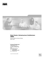
Data Center: Infrastructure Architecture SRND
Bạn đang xem bản rút gọn của tài liệu. Xem và tải ngay bản đầy đủ của tài liệu tại đây (1.67 MB, 130 trang )
Corporate Headquarters
Cisco Systems, Inc.
170 West Tasman Drive
San Jose, CA 95134-1706
USA
Tel: 408 526-4000
800 553-NETS (6387)
Fax: 408 526-4100
Data Center: Infrastructure Architecture
SRND
Solutions Reference Network Design
March, 2004
Customer Order Number: 956513
THE SPECIFICATIONS AND INFORMATION REGARDING THE PRODUCTS IN THIS MANUAL ARE SUBJECT TO CHANGE WITHOUT NOTICE. ALL
STATEMENTS, INFORMATION, AND RECOMMENDATIONS IN THIS MANUAL ARE BELIEVED TO BE ACCURATE BUT ARE PRESENTED WITHOUT
WARRANTY OF ANY KIND, EXPRESS OR IMPLIED. USERS MUST TAKE FULL RESPONSIBILITY FOR THEIR APPLICATION OF ANY PRODUCTS.
THE SOFTWARE LICENSE AND LIMITED WARRANTY FOR THE ACCOMPANYING PRODUCT ARE SET FORTH IN THE INFORMATION PACKET THAT
SHIPPED WITH THE PRODUCT AND ARE INCORPORATED HEREIN BY THIS REFERENCE. IF YOU ARE UNABLE TO LOCATE THE SOFTWARE LICENSE
OR LIMITED WARRANTY, CONTACT YOUR CISCO REPRESENTATIVE FOR A COPY.
The Cisco implementation of TCP header compression is an adaptation of a program developed by the University of California, Berkeley (UCB) as part of UCB’s public
domain version of the UNIX operating system. All rights reserved. Copyright © 1981, Regents of the University of California.
NOTWITHSTANDING ANY OTHER WARRANTY HEREIN, ALL DOCUMENT FILES AND SOFTWARE OF THESE SUPPLIERS ARE PROVIDED “AS IS” WITH
ALL FAULTS. CISCO AND THE ABOVE-NAMED SUPPLIERS DISCLAIM ALL WARRANTIES, EXPRESSED OR IMPLIED, INCLUDING, WITHOUT
LIMITATION, THOSE OF MERCHANTABILITY, FITNESS FOR A PARTICULAR PURPOSE AND NONINFRINGEMENT OR ARISING FROM A COURSE OF
DEALING, USAGE, OR TRADE PRACTICE.
IN NO EVENT SHALL CISCO OR ITS SUPPLIERS BE LIABLE FOR ANY INDIRECT, SPECIAL, CONSEQUENTIAL, OR INCIDENTAL DAMAGES, INCLUDING,
WITHOUT LIMITATION, LOST PROFITS OR LOSS OR DAMAGE TO DATA ARISING OUT OF THE USE OR INABILITY TO USE THIS MANUAL, EVEN IF CISCO
OR ITS SUPPLIERS HAVE BEEN ADVISED OF THE POSSIBILITY OF SUCH DAMAGES.
Data Cemter Networking: Enterprise Distributed Data Centers
Copyright © 2004, Cisco Systems, Inc.
All rights reserved.
CCIP, CCSP, the Cisco Arrow logo, the Cisco Powered Network mark, Cisco Unity, Follow Me Browsing, FormShare, and StackWise are trademarks of Cisco Systems, Inc.;
Changing the Way We Work, Live, Play, and Learn, and iQuick Study are service marks of Cisco Systems, Inc.; and Aironet, ASIST, BPX, Catalyst, CCDA, CCDP, CCIE, CCNA,
CCNP, Cisco, the Cisco Certified Internetwork Expert logo, Cisco IOS, the Cisco IOS logo, Cisco Press, Cisco Systems, Cisco Systems Capital, the Cisco Systems logo,
Empowering the Internet Generation, Enterprise/Solver, EtherChannel, EtherSwitch, Fast Step, GigaStack, Internet Quotient, IOS, IP/TV, iQ Expertise, the iQ logo, iQ Net
Readiness Scorecard, LightStream, MGX, MICA, the Networkers logo, Networking Academy, Network Registrar, Packet, PIX, Post-Routing, Pre-Routing, RateMUX, Registrar,
ScriptShare, SlideCast, SMARTnet, StrataView Plus, Stratm, SwitchProbe, TeleRouter, The Fastest Way to Increase Your Internet Quotient, TransPath, and VCO are registered
trademarks of Cisco Systems, Inc. and/or its affiliates in the U.S. and certain other countries.
All other trademarks mentioned in this document or Web site are the property of their respective owners. The use of the word partner does not imply a partnership relationship
between Cisco and any other company. (0304R)
iii
Data Center: Infrastructure Architecture SRND
956513
CONTENTS
Preface vii
Document Purpose vii
Document Organization viii
Obtaining Documentation viii
World Wide Web viii
Documentation CD-ROM viii
Ordering Documentation ix
Documentation Feedback ix
Obtaining Technical Assistance ix
Cisco.com ix
Technical Assistance Center x
Cisco TAC Web Site x
Cisco TAC Escalation Center xi
CHAPTER
1
Data Center Infrastructure Architecture 1-1
Data Center Architecture 1-1
Hardware and Software Recommendations 1-3
Aggregation Switches 1-3
Service Appliances 1-5
Service Modules 1-5
Access Switches 1-6
Software Recommendations 1-8
Data Center Multi-Layer Design 1-9
Core Layer 1-9
Aggregation and Access Layer 1-10
Service Switches 1-10
Server Farm Availability 1-11
Load-Balanced Servers 1-12
Data Center Protocols and Features 1-15
Layer 2 Protocols 1-15
Layer 3 Protocols 1-16
Security in the Data Center 1-18
Scaling Bandwidth 1-18
Network Management 1-19
Contents
iv
Data Center: Infrastructure Architecture SRND
956513
1-20
CHAPTER
2
Data Center Infrastructure Design 2-1
Routing Between the Data Center and the Core 2-1
Layer 3 Data Center Design 2-1
Using OSPF 2-3
Using EIGRP 2-7
Designing Layer 3 Security 2-8
Switching Architecture for the Server Farm 2-9
Using Redundant Supervisors 2-9
Layer 2 Data Center Design 2-10
Using Three-Tier and Two-Tier Network Designs 2-10
Layer 2 and Layer 3 Access Design 2-11
Using VLANs to Segregate Server Farms 2-12
VLAN Scalability 2-13
Using Virtual Trunking Protocol 2-14
Choosing a Spanning-Tree Algorithm 2-14
Using Loopguard and UDLD 2-15
Using PortFast and TrunkFast 2-17
Using a Loop-Free Topology 2-18
Designing Layer 2 Security 2-19
Assigning the Default Gateway in the Data Center 2-21
Using Gateway Redundancy Protocols 2-22
Tuning the ARP Table 2-23
CHAPTER
3
HA Connectivity for Servers and Mainframes: NIC Teaming and OSA/OSPF Design 3-1
Overview 3-1
Ensuring Server Farm and Mainframe Availability 3-2
Load Balanced Servers 3-4
NIC Teaming 3-4
Mainframe Sysplex 3-6
NIC Teaming Architecture Details 3-7
Hardware and Software 3-8
Deployment Modes 3-8
Fault Tolerance Modes 3-8
Load Balancing Modes 3-12
Link Aggregation Modes 3-13
Layer 3 Multihoming 3-14
Interoperability with Security 3-16
Contents
v
Data Center: Infrastructure Architecture SRND
956513
Intrusion Detection 3-17
Port Security 3-17
Private VLANs 3-19
Mainframe OSA and OSPF Architecture Details 3-20
Overview 3-20
Attachment Options 3-21
IP Addressing 3-22
OSPF Routing on a Mainframe 3-23
Sysplex 3-24
Configuration Details 3-26
Speed and Duplex Settings 3-27
Layer 2 Implementation 3-27
Spanning Tree 3-27
PortFast and BPDU Guard 3-28
Port Security 3-29
Server Port Configuration 3-29
CHAPTER
4
Data Center Infrastructure Configuration 4-1
Configuring Network Management 4-1
Username and Passwords 4-1
VTY Access 4-2
SNMP 4-3
Logging 4-3
VLAN Configuration 4-3
Spanning Tree Configuration 4-6
Rapid PVST+ 4-6
MST 4-7
Protection From Loops 4-7
VLAN Interfaces and HSRP 4-8
Switch-To-Switch Connections Configuration 4-9
Channel Configuration 4-9
Trunk Configuration 4-10
Server Port Configuration 4-12
Speed and Duplex Settings 4-12
PortFast and BPDU Guard 4-13
Port Security 4-13
Configuration Example 4-14
Sample Configurations 4-14
Aggregation1 4-14
Contents
vi
Data Center: Infrastructure Architecture SRND
956513
Aggregation2 4-18
Access 4-21
G
LOSSARY
I
NDEX
vii
Data Center: Infrastructure Architecture SRND
956513
Preface
This publication provides solution guidelines for enterprises implementing Data Centers with Cisco
devices. The intended audiences for this design guide include network architects, network managers, and
others concerned with the implementation of secure Data Center solutions, including:
•
Cisco sales and support engineers
•
Cisco partners
•
Cisco customers
Document Purpose
The convergence of voice and video in today’s enterprise networks has placed additional requirements
on the infrastructure of enterprise data centers, which must provide the following services:
•
Hosting enterprise-wide servers
•
Supporting critical application services
•
Supporting traditional data services
•
24X7 availability
These requirements are based on the applications supported rather than the size of the data center. The
process of selecting the proper data center hardware and software versions that meet the necessary Layer
2, Layer 3, QoS, and Multicast requirements can be a daunting task. This solutions reference network
design (SRND) provides design and implementation guidelines for building a redundant, scalable
enterprise data center. These guidelines cover the following areas:
•
Data center infrastructure and server farm design
•
Server farm design including high availability
•
Designing data centers for mainframe connectivity
•
Enhancing server-to-server communication
viii
Data Center: Infrastructure Architecture SRND
956513
Preface
Document Organization
Document Organization
This document consists of the following chapters:
Obtaining Documentation
The following sections explain how to obtain documentation from Cisco Systems.
World Wide Web
You can access the most current Cisco documentation on the World Wide Web at the following URL:
Translated documentation is available at the following URL:
/>Documentation CD-ROM
Cisco documentation and additional literature are available in a Cisco Documentation CD-ROM
package, which is shipped with your product. The Documentation CD-ROM is updated monthly and may
be more current than printed documentation. The CD-ROM package is available as a single unit or
through an annual subscription.
Chapter Description
Chapter 1, “Data Center Infrastructure
Architecture”
Provides background information, including
hardware recommendations for designing a data
center infrastructure that is secure, scalable, and
resilient.
Chapter 2, “Data Center Infrastructure Design” Describes design issu, including routing between
the data center and the core, switching within the
server farm
Chapter 3, “HA Connectivity for Servers and
Mainframes: NIC Teaming and OSA/OSPF
Design”
Describes how to include server connectivity with
NIC teaming and mainframe connectivity in your
data center infrastructure architcture.
Chapter 4, “Data Center Infrastructure
Configuration”
Provides configuration procedures and sample
listings for implementing the recommended
infrastructure architecture.
ix
Data Center: Infrastructure Architecture SRND
956513
Preface
Obtaining Technical Assistance
Ordering Documentation
Cisco documentation is available in the following ways:
•
Registered Cisco Direct Customers can order Cisco product documentation from the Networking
Products MarketPlace:
/>•
Registered Cisco.com users can order the Documentation CD-ROM through the online Subscription
Store:
/>•
Nonregistered Cisco.com users can order documentation through a local account representative by
calling Cisco corporate headquarters (California, USA) at 408 526-7208 or, elsewhere in North
America, by calling 800 553-NETS (6387).
Documentation Feedback
If you are reading Cisco product documentation on Cisco.com, you can submit technical comments
electronically. Click Leave Feedback at the bottom of the Cisco Documentation home page. After you
complete the form, print it out and fax it to Cisco at 408 527-0730.
You can e-mail your comments to
To submit your comments by mail, use the response card behind the front cover of your document, or
write to the following address:
Cisco Systems
Attn: Document Resource Connection
170 West Tasman Drive
San Jose, CA 95134-9883
We appreciate your comments.
Obtaining Technical Assistance
Cisco provides Cisco.com as a starting point for all technical assistance. Customers and partners can
obtain documentation, troubleshooting tips, and sample configurations from online tools by using the
Cisco Technical Assistance Center (TAC) Web Site. Cisco.com registered users have complete access to
the technical support resources on the Cisco TAC Web Site.
Cisco.com
Cisco.com is the foundation of a suite of interactive, networked services that provides immediate, open
access to Cisco information, networking solutions, services, programs, and resources at any time, from
anywhere in the world.
Cisco.com is a highly integrated Internet application and a powerful, easy-to-use tool that provides a
broad range of features and services to help you to
•
Streamline business processes and improve productivity
•
Resolve technical issues with online support
x
Data Center: Infrastructure Architecture SRND
956513
Preface
Obtaining Technical Assistance
•
Download and test software packages
•
Order Cisco learning materials and merchandise
•
Register for online skill assessment, training, and certification programs
You can self-register on Cisco.com to obtain customized information and service. To access Cisco.com,
go to the following URL:
Technical Assistance Center
The Cisco TAC is available to all customers who need technical assistance with a Cisco product,
technology, or solution. Two types of support are available through the Cisco TAC: the Cisco TAC
Web Site and the Cisco TAC Escalation Center.
Inquiries to Cisco TAC are categorized according to the urgency of the issue:
•
Priority level 4 (P4)—You need information or assistance concerning Cisco product capabilities,
product installation, or basic product configuration.
•
Priority level 3 (P3)—Your network performance is degraded. Network functionality is noticeably
impaired, but most business operations continue.
•
Priority level 2 (P2)—Your production network is severely degraded, affecting significant aspects
of business operations. No workaround is available.
•
Priority level 1 (P1)—Your production network is down, and a critical impact to business operations
will occur if service is not restored quickly. No workaround is available.
Which Cisco TAC resource you choose is based on the priority of the problem and the conditions of
service contracts, when applicable.
Cisco TAC Web Site
The Cisco TAC Web Site allows you to resolve P3 and P4 issues yourself, saving both cost and time. The
site provides around-the-clock access to online tools, knowledge bases, and software. To access the
Cisco TAC Web Site, go to the following URL:
/>All customers, partners, and resellers who have a valid Cisco services contract have complete access to
the technical support resources on the Cisco TAC Web Site. The Cisco TAC Web Site requires a
Cisco.com login ID and password. If you have a valid service contract but do not have a login ID or
password, go to the following URL to register:
/>If you cannot resolve your technical issues by using the Cisco TAC Web Site, and you are a Cisco.com
registered user, you can open a case online by using the TAC Case Open tool at the following URL:
/>If you have Internet access, it is recommended that you open P3 and P4 cases through the Cisco TAC
Web Site.
xi
Data Center: Infrastructure Architecture SRND
956513
Preface
Obtaining Technical Assistance
Cisco TAC Escalation Center
The Cisco TAC Escalation Center addresses issues that are classified as priority level 1 or priority
level 2; these classifications are assigned when severe network degradation significantly impacts
business operations. When you contact the TAC Escalation Center with a P1 or P2 problem, a Cisco TAC
engineer will automatically open a case.
To obtain a directory of toll-free Cisco TAC telephone numbers for your country, go to the following
URL:
/>Before calling, please check with your network operations center to determine the level of Cisco support
services to which your company is entitled; for example, SMARTnet, SMARTnet Onsite, or Network
Supported Accounts (NSA). In addition, please have available your service agreement number and your
product serial number.
xii
Data Center: Infrastructure Architecture SRND
956513
Preface
Obtaining Technical Assistance
CHAPTER
1-1
Data Center: Infrastructure Architecture SRND
956513
1
Data Center Infrastructure Architecture
This chapter provides background information for designing a secure, scalable, and resilient data cen-
ter infrastructure. It includes the following sections:
•
Data Center Architecture
•
Hardware and Software Recommendations
•
Data Center Multi-Layer Design
•
Data Center Protocols and Features
•
Scaling Bandwidth
•
Network Management
Data Center Architecture
This section describes the basic architecture for a secure, scalable, and resilient data center infrastruc-
ture. The term infrastructure in this design guide refers to the Layer 2 and Layer 3 configurations that
provide network connectivity to the server farm as well as the network devices that provide security and
application-related functions. Data centers are composed of devices that provide the following functions:
•
Ensuring network connectivity, including switches and routers
•
Providing network and server security, including firewalls and Intrusion Detection Systems (IDSs)
•
Enhancing availability and scalability of applications, including load balancers, Secure Sockets
Layer (SSL) offloaders and caches
In addition, a Network Analysis Module (NAM) is typically used to monitor the functioning of the network
and the performance of the server farm.
The following are critical requirements when designing the data center infrastructure to meet service level
expectations:
•
High Availability—Avoiding a single point of failure and achieving fast and predictable
convergence times
•
Scalability—Allowing changes and additions without major changes to the infrastructure, easily
adding new services, and providing support for hundreds dual-homed servers
•
Simplicity—Providing predictable traffic paths in steady and failover states, with explicitly defined
primary and backup traffic paths
1-2
Data Center: Infrastructure Architecture SRND
956513
Chapter 1 Data Center Infrastructure Architecture
Data Center Architecture
•
Security—Prevent flooding, avoid exchanging protocol information with rogue devices, and
prevent unauthorized access to network devices
The data center infrastructure must provide port density and Layer 2 and Layer 3 connectivity, while
supporting security services provided by access control lists (ACLs), firewalls and intrusion detection
systems (IDS). It must support server farm services such as content switching, caching, SSL offloading
while integrating with multi-tier server farms, mainframes, and mainframe services (TN3270, load
balancing and SSL offloading).
While the data center infrastructure must be scalable and highly available, it should still be simple to
operate, troubleshoot, and must easily accommodate new demands.
Figure 1-1 Data Center Architecture
Figure 1-1 shows a high-level view of the Cisco Data Center Architecture. As shown, the design follows the
proven Cisco multilayer architecture, including core, aggregation, and access layers. Network devices are
deployed in redundant pairs to avoid a single point of failure. The examples in this design guide use the
Catalyst 6500 with Supervisor 2 in the aggregation layer, Gigabit Ethernet, and Gigabit EtherChannel links.
114028
Mainframe
Aggregation layer
Access
Load
balancer
Firewall SSL
offloader
Cache
Network
analysis
IDS sensor
Enterprise
campus core
1-3
Data Center: Infrastructure Architecture SRND
956513
Chapter 1 Data Center Infrastructure Architecture
Hardware and Software Recommendations
Hardware and Software Recommendations
This section summarizes the recommended hardware and software for implementing a highly available,
secure and scalable data center intrastructure. It includes the following topics:
•
Aggregation Switches
•
Service Appliances and Service Modules
•
Access Switches
•
Software Recommendations
Aggregation Switches
The following are some of the factors to use in choosing the aggregation layer device:
•
Forwarding performance
•
Density of uplink ports
•
Support for 10 Gigabit Ethernet linecards
•
Support for 802.1s, 802.1w, Rapid-PVST+
•
Support for MPLS-VPNs
•
Support for hardware-based NAT
•
Support for uRPF in hardware
•
QoS characteristics
•
Support for load balancing and security services (service modules)
At the aggregation layer, Cisco recommends using Catalyst 6500 family switches because the Catalyst 6500
chassis supports service modules for load balancing and security, including the following:
•
Content Service Module (CSM)
•
SSL Service Module (SSLSM)
•
Firewall Service Module (FWSM)
•
Intrusion Detection Service Module (IDSM)
•
Network Analysis Module (NAM)
The chassis configuration depends on the specific services you want to support at the aggregation layer, the
port density of uplinks and appliances, and the need for supervisor redundancy. Load balancing and security
services can also be provided by external service appliances, such as PIX Firewalls; Content Services
Switches, Secure Content Accelerators and Content Engines.
You also typically attach mainframes to the aggregation switches, especially if you configure each
connection to the optical server adapters (OSA) card as a Layer 3 link. In addition, you can use the
aggregation switches to attach caches for Reverse Proxy Caching. You can also directly attach servers to the
aggregation switches if the port density of the server farm doesn’t require using access switches.
Note
The Supervisor 2 (Sup2) and Sup720 are both recommended, but this design guide is intended for use
with Sup2. Another design guide will describe the use of Sup720, which provides higher performance
and additional functionalities in hardware and is the best choice to build a 10-Gigabit Ethernet data
center infrastructure..
1-4
Data Center: Infrastructure Architecture SRND
956513
Chapter 1 Data Center Infrastructure Architecture
Hardware and Software Recommendations
The Catalyst 6500 is available in several form factors:
•
6503: 3 slots 3 RUs
•
6506: 6 slots 12 RUs
•
7606: 6 slots 7 RUs
•
6509: 9 slots 15 RUs
•
6513: 13 slots, 19 RUs
The 6509 and 6513 are typically deployed in the data center because they provide enough slots for access
ports and service modules, such as IDS.
The 6500 chassis support a 32 Gbps shared bus, a 256 Gbps fabric (SFM2) and a 720 Gbps fabric (if using
Sup720). With a 6509, the Sup2 connects to slot 1 or 2 and the switch fabric (or the Sup720) connects to slot
5 or slot 6. With a 6513, the Sup2 connects to slot 1 or 2, and the switch fabric (or the Sup720) connects to
the slot 7 or slot 8.
If you use the fabric module (SFM2) with Sup2, each slot in a 6509 receives 16 Gbps of channel attachment.
Slots 1-8 in a 6513 receive 8 Gbps and slots 9-13 receive 16 Gbps of channel attachment.
If you use Sup720, which has an integrated fabric, each slot in a 6509 receives 40 Gbps of channel
attachment. Slots 1-8 in a 6513 receive 20 Gbps, and slots 9-13 receive 40 Gbps of channel attachment.
Catalyst 6509 Hardware Configuration
A typical configuration of a Catalyst 6509 in the aggregation of a data center looks like this:
•
Sup2 with MSFC2
•
FWSM (fabric attached at 8 Gbps)
•
CSM
•
SSLSM (fabric attached at 8 Gbps)
•
IDSM-2 (fabric attached at 8 Gbps)
•
WS-X6516A-GBIC or WS-X6516-GBIC – 16 Gigabit Ethernet Fiber Ports – Jumbo (9216 B) –
(fabric attached at 8 Gbps) for uplink connectivity with the access switches
•
WS-X6516A-GBIC or WS-X6516-GBIC – 16 Gigabit Ethernet Fiber Ports – Jumbo (9216 B) –
(fabric attached at 8 Gbps) for uplink connectivity with the access switches
•
WS-X6516-GE-TX – 16 10/100/1000 BaseT– Jumbo – (fabric attached at 8 Gbps) for servers and
caches
If you use a fabric module, this would plug into slot 5 or 6. Because sup720 has an integrated fabric, this one
would also plug into slot 5 or 6.
Catalyst 6513 Hardware Configuration
A typical configuration of a Catalyst 6513 in the aggregation of a data center looks like this:
•
Sup2 with MSFC2
•
FWSM (fabric attached at 8 Gbps)
•
CSM
•
SSLSM (fabric attached at 8 Gbps)
•
IDSM-2 (fabric attached at 8 Gbps)
1-5
Data Center: Infrastructure Architecture SRND
956513
Chapter 1 Data Center Infrastructure Architecture
Hardware and Software Recommendations
•
NAM-2 (fabric attached at 8 Gbps)
•
WS-X6516A-GBIC or WS-X6516-GBIC – 16 Gigabit Ethernet Fiber Ports – Jumbo (9216 B) –
(fabric attached at 8 Gbps) for uplink connectivity with the access switches
•
WS-X6516A-GBIC or WS-X6516-GBIC – 16 Gigabit Ethernet Fiber Ports – Jumbo (9216 B) –
(fabric attached at 8 Gbps) for uplink connectivity with the access switches
•
WS-X6516-GE-TX – 16 10/100/1000 BaseT– Jumbo (9216 B) – (fabric attached at 8 Gbps) for
servers and caches
If you use a fabric module, this would plug into slot 7 or 8. Because sup720 has an integrated fabric, this one
would also plug into slot 7 or 8.
It is also good practice to use the first 8 slots for service modules because these are fabric attached with a
single 8 Gbps channel. Use the remaining slots for Ethernet line cards because these might use both fabric
channels.
Note
When upgrading the system to Sup720 you can keep using the linecards WS-6516-GE-TX,
WS-6516-GBIC, WS-6516A-GBIC
Service Appliances
Service appliances are external networking devices that include the following:
•
Content Service Switch (CSS, CSS11506): 5 RUs, 40 Gbps of aggregate throughput, 2,000
connections per second per module (max 6 modules), 200,000 concurrent connections with 256 MB
DRAM.
•
CSS11500 SSL decryption module (for the CSS11500 chassis): Performance numbers per module:
1,000 new transactions per second, 20,000 concurrent sessions, 250 Mbps of throughput.
•
PIX Firewalls (PIX 535): 3 RU, 1.7 Gpbs of throughput, 500,000 concurrent connections
•
IDS sensors (IDS 4250XL): 1 RU, 1 Gbps (with the XL card)
•
Cisco Secure Content Accelerator 2: 1 RU, 800 new transactions per second, 20,000 concurrent
sessions, 70 Mbps of bulk transfer
The number of ports that these appliances require depends entirely on how many appliances you use and
how you configure the Layer 2 and Layer 3 connectivity between the appliances and the infrastructure.
Service Modules
Security and load balancing services in the data center can be provided either with appliances or with
Catalyst 6500 linecards. The choice between the two family of devices is driven by considerations of
performance, rack space utilization, cabling and of course features that are specific to each of the devices.
Service modules are cards that you plug into the Catalyst 6500 to provide firewalling, intrusion detection,
content switching, and SSL offloading. Service modules communicate with the network through the
Catalyst backplane and can be inserted without the need for additional power or network cables.
Service modules provide better rack space utilisation, simplified cabling, better integration between the
modules and higher performance than typical appliances. When using service modules, certain
configurations that optimize the convergence time and the reliability of the network are automatic. For
1-6
Data Center: Infrastructure Architecture SRND
956513
Chapter 1 Data Center Infrastructure Architecture
Hardware and Software Recommendations
example, when you use an external appliance, you need to manually configure portfast or trunkfast on the
switch port that connects to the appliance. This configuration is automatic when you use a service module.
As an example of rack space utilization consider that a PIX 535 firewall takes 3 Rack Units (RUs), while a
Firewall Services Module (FWSM) takes one slot in a Catalyst switch, which means that a FWSM inside a
Catalyst 6513 takes (19 RU / 13 slots) = 1.4 RUs.
Another advantage of using service modules as opposed to external appliances is that service modules are
VLAN aware, which makes consolidation and virtualization of the infrastructure easier.
Each service module provides a different functionality and takes one slot out of the Catalyst 6500. Examples
of these modules include the following:
•
CSM: 165,000 connections per second, 1,000,000 concurrent connections, 4 Gbps of throughput.
•
FWSM: 8 Gpbs fabric attached . Performance numbers: 100,000 cps, 5.5Gbps of throughput,
1,000,000 cc.
•
SSLSM: 8 Gbps fabric attached. Performance numbers: 3000 new transactions per second, 60,000
concurrent connections, 300 Mbps of throughput.
•
IDSM-2: 8 Gbps fabric attached. Performance: 600 Mbps
Access Switches
This section describes how to select access switches for your data center intrastructure design and describes
some of the Cisco Catalyst products that are particularly useful. It includes the following topics:
•
Selecting Access Switches
•
Catalyst 6500
•
Catalyst 4500
•
Catalyst 3750
Selecting Access Switches
The following are some of the factors to consider when choosing access layer switches:
•
Forwarding performance
•
Oversubscription rates
•
Support for 10/100/1000 linecards
•
Support for 10 Gigabit Ethernet (for uplink connectivity)
•
Support for Jumbo Frames
•
Support for 802.1s, 802.1w, Rapid-PVST+
•
Support for stateful redundancy with dual supervisors
•
Support for VLAN ACLs (used in conjunction with IDS)
•
Support for Layer 2 security features such as port security and ARP inspection
•
Support for private VLANs
•
Support for SPAN and Remote SPAN (used in conjunction with IDS)
•
Support for QoS
1-7
Data Center: Infrastructure Architecture SRND
956513
Chapter 1 Data Center Infrastructure Architecture
Hardware and Software Recommendations
•
Modularity
•
Rack space and cabling efficiency
•
Power redundancy
Cost often requires choosing less expensive server platforms that only support one NIC card. To provide
availability for these single-homed servers you need to use dual supervisors in the access switch. For
dual supervisor redundancy to be effective you need stateful failover at least to Layer 2.
When choosing linecards or other products to use at the access layer, consider how much
oversubscription a given application tolerates. When choosing linecards, you should also consider
support for Jumbo frames and the maximum queue size.
Modular switches support both oversubscribed and non-oversubscribed linecards. Typically, you use
oversubscribed linecards as access ports for server attachment and non-oversubscribed linecards for
uplink ports or channels between switches. You might need to use non-oversubscribed linecards for the
server ports as well, depending on the amount of traffic that you expect a server to generate.
Although various platforms can be used as access switches, this design guide uses the Catalyst 6506. Using
service modules in an access switch can improve rack space utilization and reduce cabling if you deploy
load balancing and security at the access layer.
From the data center design perspective, the access layer (front-end switches) must support 802.1s/1w and
Rapid PVST+ to take advantage of rapid convergence.
The 10/100/1000 technology allows incremental adoption of Gigabit Ethernet in the server farm thanks to
the compatibility between FastEthernet NIC cards and 10/100/1000 switch linecards. 10 Gigabit Ethernet is
becoming the preferred technology for the data center uplinks within the data center and between the data
center and the core.
Cabling between the servers and the switch can be either fiber or copper. Gigabit over copper can run on the
existing Cat 5 cabling used for Fast Ethernet (ANSI/TIA/EIA 568-A, ISO/IEC 11801-1995). Cat 5 cabling
was designed for the use of 2 cable pairs, but Gigabit Ethernet uses 4 pairs. Existing Cat 5 wiring
infrastructure must be tested to ensure it can effectively support Gigabit rates. New installations of Gigabit
Ethernet over copper should use at least Cat 5e cabling or, better, Cat 6.
Note
For more information on the cabling requirements of 1000BaseT refer to the document “Gigabit Ethernet
Over Copper Cabling” published on www.gigabitsolution.com
Catalyst 6500
The Catalyst 6500 supports all the technologies and features required for implementing a highly available,
secure, and scalable data center intrastructure. The platform used in this design guide for the access
switches is the 6506 because it provides enough slots for access ports and service modules together with
efficient rack space utilisation.
A typical configuration for the Catalyst 6500 in the access layer is as follows:
•
Single or dual supervisors (two supervisors are recommended for single-homed servers)
•
IDSM-2
•
Access ports for the servers 10/100/1000 linecards: WS-6516-GE-TX – Jumbo (9216 B), fabric
attached at 8 Gbps
•
Gigabit linecard for uplink connectivity: WS-6516-GBIC or WS-6516A-GBIC – Jumbo (9216 B),
fabric attached at 8 Gbps
1-8
Data Center: Infrastructure Architecture SRND
956513
Chapter 1 Data Center Infrastructure Architecture
Hardware and Software Recommendations
Note
It is possible to attach 1000BaseT GBIC adapters to Optical Gigabit linecards by using the WS-G5483
GBIC
If the Catalyst 6506 is upgraded to Sup720, Sup720 will be plugged into slot 5 or slot 6. For this reason
when using Sup2 it is practical to keep either slot empty for a possible upgrade or to insert a fabric module.
When upgrading the system to Sup720 you can keep using the linecards WS-6516-GE-TX, WS-6516-GBIC,
WS-6516A-GBIC
Catalyst 4500
The Catalyst 4500, which can also be used as an access switch in the data center is a modular switch
available with the following chassis types:
•
4503: 3 slots, 7 RUs
•
4506: 6 slots, 10 RUs
•
4507R: 7 slots, 11 RUs (slot 1 and 2 are reserved for the supervisors and do not support linecards)
Only the 4507R supports dual supervisors. A typical configuration with supervisor redundancy and layer 2
access would be as follows:
•
Dual Sup2-plus (mainly layer 2 + static routing and RIP) or dual supervisor IV (for layer 3 routing
protocols support with hardware CEF)
•
Gigabit copper attachment for servers, which can use one of the following:
•
WS-4306-GB with copper GBICs (WS-G5483)
•
24-port 10/100/1000 WS-X4424-GB-RJ45
•
12-port 1000BaseT linecard WS-X4412-2GB-T
•
Gigabit fiber attachment for servers, which can use a WS-X4418-GB (this doesn’t support copper
GBICs)
•
Gigabit linecard for uplink connectivity: WS-4306-GB – Jumbo (9198 B)
Note
Jumbo frames are only supported on non-oversubscribed ports.
When internal redundancy is not required, you don’t need to use a 4507 chassis and you can use a Supervisor
3 for Layer 3 routing protocol support and CEF switching in hardware.
Catalyst 3750
The Catalyst 3750 is a stackable switch that supports Gigabit Ethernet, such as the 24-port 3750G-24TS
with 10/100/1000 ports and 4 SFP for uplink connectivity. Several 3750s can be clustered together to
logically form a single switch. In this case, you could use 10/100/1000 switches (3750-24T) clustered with
an SFP switch (3750G-12S) for EtherChannel uplinks.
Software Recommendations
Because of continous improvements in the features that are supported on the access switch platforms
1-9
Data Center: Infrastructure Architecture SRND
956513
Chapter 1 Data Center Infrastructure Architecture
Data Center Multi-Layer Design
described in this design document, it isn't possible to give a recommendation on the software release you
should deploy in your data center.
The choice of the software release depends on the hardware that the switch needs to support and on the
stability of a given version of code. In a data center design, you should use a release of code that has been
released for a long time, is available with several re-builds, and where the newer builds contain only bug
fixes.
When using Catalyst family products, you must choose between using the Supervisor IOS operating system
or the Catalyst IOS operating systems. These two operating systems have some important differences in the
CLI, the features supported, and the hardware supported.
This design document uses supervisor IOS on the Catalyst 6500 aggregation switches because it supports
Distributed Forwarding Cards, and because it was the first operating system to support the Catalyst service
modules. Also, it is simpler to use a single standardized image and a single operating system on all the data
center devices
The following summarizes the features introduced with different releases of the software:
•
12.1(8a)E—Support for Sup2 and CSM
•
12.1(13)E—Support for Rapid PVST+ and for FWSM, NAM2 with Sup2, and SSLSM with Sup2
•
12.1(14)E—Support for IDSM-2 with Sup2
•
12.1(19)E—Support for some of the 6500 linecards typically used in data centers and SSHv2
This design guide is based on testing with Release 12.1(19)Ea1.
Data Center Multi-Layer Design
This section describes the design of the different layers of the data center infrastructure. It includes the
following topics:
•
Core Layer
•
Aggregation Layer
•
Access Layer
•
Service Switches
•
Server Availability
Core Layer
The core layer in an enterprise network provides connectivity among the campus buildings, the private
WAN network, the Internet edge network and the data center network. The main goal of the core layer is to
switch traffic at very high speed between the modules of the enterprise network. The configuration of the
core devices is typically kept to a minimum, which means pure routing and switching. Enabling additional
functions might bring down the performance of the core devices.
There are several possible types of core networks. In previous designs, the core layer used a pure Layer 2
design for performance reasons. However, with the availability of Layer 3 switching, a Layer 3 core is as
fast as a Layer 2 core. If well designed, a Layer 3 core can be more efficient in terms of convergence time
and can be more scalable.
1-10
Data Center: Infrastructure Architecture SRND
956513
Chapter 1 Data Center Infrastructure Architecture
Data Center Multi-Layer Design
For an analysis of the different types of core, refer to the white paper available on www.cisco.com:
“Designing High-Performance Campus Intranets with Multilayer Switching” by Geoff Haviland.
The data center described in this design guide connects to the core using Layer 3 links. The data center
network is summarized and the core injects a default into the data center network. Some specific
applications require injecting host routes (/32) into the core.
Aggregation and Access Layer
The access layer provides port density to the server farm, while the aggregation layer collects traffic from
the access layer and connects the data center to the core. The aggregation layer is also the preferred
attachment point for mainframes and the attachment point for caches used in Reverse Proxy Cache mode.
Security and application service devices (such as load balancing devices, SSL offloading devices, firewalls
and IDS devices) are deployed either at the aggregation or access layer. Service devices deployed at the
aggregation layer are shared among all the servers, while services devices deployed at the access layer
provide benefit only to the servers that are directly attached to the specific access switch.
The design of the access layer varies depending on whether you use Layer 2 or Layer 3 access. Layer 2
access is more efficient for sharing aggregation layer services among the servers. For example, to deploy a
firewall that is used by all the servers in the data center, deploy it at the aggregation layer. The easiest
implementation is with the firewall Layer 2 adjacent to the servers because the firewall should see both
client-to-server and server-to-client traffic.
Security and application services are provided by deploying external appliances or service modules. The
Cisco preferred architecture for large-scale server farms uses service modules for improved integration and
consolidation. A single service module can often replace multiple external appliances with a single linecard.
Figure 1-1 shows the aggregation switches with firewalling, IDS, load balancing, SSL offloading and NAM
in the same switch. This configuration needs to be customized for specific network requirements and is not
the specific focus of this document. For information about designing data centers with service modules, refer
to .
Service Switches
The architecture shown in Figure 1-1 is characterized by high density in service modules on each
aggregation switch, which limits the number of ports available for uplink connectivity. It is also possible that
the code versions required by the service modules may not match the software version already used on the
aggregation switches in the data center environment.
Figure 1-2 illustrates the use of service switches in a data center. Service switches are Catalyst 6500
populated with service modules and dual-attached to the aggregation switches. When used with service
modules, they allow higher port density and separate the code requirements of the service modules from
those of the aggregation switches.
1-11
Data Center: Infrastructure Architecture SRND
956513
Chapter 1 Data Center Infrastructure Architecture
Data Center Multi-Layer Design
Figure 1-2 Data Center Architecture with Service Switches
Using service switches is very effective when not all the traffic requires the use of service devices. Traffic
that doesn't can take the path to the core through the aggregation switches. For example, by installing a
Content Switching Module in a service switch, the servers that require load balancing are configured on a
“server VLAN” that brings the traffic to the service switches. Servers that don’t require load balancing are
configured on a VLAN that is terminated on the aggregation switches.
On the other hand, in a server farm, all the servers are typically placed behind one or more Firewall Service
Modules (FWSM). Placing an FWSM in a service switch would require all the traffic from the server farm
to flow through the service switch and no traffic would use the aggregation switches for direct access to the
core. The only benefit of using a service switch with FWSM is an increased number of uplink ports at the
aggregation layer. For this reason, it usually makes more sense to place an FWSM directly into an
aggregation switch.
By using service switches, you can gradually move the servers behind service modules and eventually
replace the aggregation switches with the service switches.
Server Farm Availability
Server farms in a data center have different availability requirements depending on whether they host
114029
Mainframe
Aggregation layer
Access
Load
balancer
Firewall SSL
offloader
Cache
Network
analysis
IDS sensor
Enterprise
campus core
1-12
Data Center: Infrastructure Architecture SRND
956513
Chapter 1 Data Center Infrastructure Architecture
Data Center Multi-Layer Design
business-critical applications or applications with less stringent availability requirements, such as
development applications. You can meet availability requirements by leveraging specific software
technologies and network technologies, including the following:
Applications can be load-balanced either with a network device or with clustering software
Servers can be multi-homed with multiple NIC cards
Access switches can provide maximum availability if deployed with dual supervisors
Load-Balanced Servers
Load-balanced servers are located behind a load balancer, such as CSM. Load-balanced server farms
typically include the following kinds of servers:
•
Web and application servers
•
DNS servers
•
LDAP servers
•
RADIUS servers
•
TN3270 servers
•
Streaming servers
Note
The document at the following URL outlines some of the popular applications of load balancing:
/>Load-balanced server farms benefit from load distribution, application monitoring, and application-layer
services, such as session persistence. On the other hand, while the 4 Gbps throughput of a CSM is sufficient
in most client-to-server environments, it could be a bottleneck for bulk server-to-server data transfers in
large-scale server farms.
When the server farm is located behind a load balancer, you may need to choose one of the following
options to optimize server-to-server traffic:
•
Direct Server Return
•
Performing client NAT on the load balancer
•
Policy Based Routing
The recommendations in this document apply to network design with a CSM and should be deployed before
installing the CSM.
A key difference between load-balanced servers and non-load balanced servers is the placement of the
default gateway. Non-load balanced servers typically have their gateway configured as a Hot Standby
Routing Protocol (HSRP) address on the router inside the Catalyst 6500 switch or on the firewall device.
Load-balanced servers may use the IP address of the load balancing device as their default gateway.
Levels of Server Availability
Each enterprise categorizes its server farms based on how critical they are to the operation of the business.
Servers that are used in production and handle sales transaction are often dual-homed and configured for
“switch fault tolerance.” This means the servers are attached with two NIC cards to separate switches, as
shown in Figure 1-1. This allows performing maintenance on one access switch without affecting access to
1-13
Data Center: Infrastructure Architecture SRND
956513
Chapter 1 Data Center Infrastructure Architecture
Data Center Multi-Layer Design
the server.
Other servers, such as those used for developing applications, may become inaccessible without
immediately affecting the business. You can categorize the level of availability required for different servers
as follows:
•
Servers configured with multiple NIC cards each attached to a different access switch (switch fault
tolerance) provide the maximum possible availability. This option is typically reserved to servers
hosting business critical applications.
•
Development servers could also use two NICs that connect to a single access switch which has two
supervisors. This configuration of the NIC cards goes under the name of “adapter fault tolerance”.
The two NICs should be attached to different linecards.
•
Development servers that are less critical to the business can use one NIC connected to a single
access switch (which has two supervisors)
•
Development servers that are even less critical can use one NIC connected to a single access switch
which has a single supervisor
The use of access switches with two supervisors provides availability for servers that are attached to a single
access switch. The presence of two supervisors makes it possible to perform software upgrades on one
supervisor with minimal disruption of the access to the server farm.
Adapter fault tolerance means that the server is attached with each NIC card to the same switch but each
NIC card is connected to a different linecard in the access switch.
Switch fault tolerance and adapter fault tolerance are described in Chapter 3, “HA Connectivity for
Servers and Mainframes: NIC Teaming and OSA/OSPF Design.”
Multi-Tier Server Farms
Today, most web-based applications are built as multi-tier applications. The multi-tier model uses software
running as separate processes on the same machine, using interprocess communication, or on different
machines with communications over the network. Typically, the following three tiers are used:
•
Web-server tier
•
Application tier
•
Data base tier
Multi-tier server farms built with processes running on separate machines can provide improved resiliency
and security. Resiliency is improved because a server can be taken out of service while the same function is
still provided by another server belonging to the same application tier. Security is improved because an
attacker can compromise a web server without gaining access to the application or to the database.
Resiliency is achieved by load balancing the network traffic between the tiers, and security is achieved by
placing firewalls between the tiers. You can achieve segregation between the tiers by deploying a separate
infrastructure made of aggregation and access switches or by using VLANs.
Figure 1-3 shows the design of multi-tier server farms with physical segregation between the server farm
tiers. Side (a) of the figure shows the design with external appliances, while side (b) shows the design
with service modules