Configure Routing between the RSM and an External Router Connected to an ISP
Bạn đang xem bản rút gọn của tài liệu. Xem và tải ngay bản đầy đủ của tài liệu tại đây (49.94 KB, 13 trang )
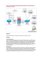
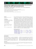
Lab 6.2.4: Configure Routing between the RSM and an External Router
Connected to an ISP
Accounting
VLAN10
10.1.10.0/24
Marketing
VLAN20
10.1.20.0/24
FEC Trunk
802.1q
10.1.1.0/24
Native
VLAN1
Engineering
VLAN30
10.1.30.0/24
10.1.30.2
Engineering Workstation
ALSwitch
2900XL
10.1.1.251/24
ISP
Lo0
200.200.2.0/24
DLSwitch
4006
10.1.1.250/24
Internet
VLAN2
10.1.2.0/24
CORP
2600
10.1.2.1/24
Serial 0/1 DCE
200.200.1.0/24
Serial 0/1 DTE
10.1.1.1/24
DLRouter
Objective:
Configure routing between the RSM and an external router connected to an ISP
Scenario:
Current Environment
Your network switching equipment currently includes a 4006 Core switch and a 2900XL access
switch. Your network is segmented into four functional VLANs for better network management.
VLANs include “Accounting”, “Marketing” and “Engineering” for the users and “default” used for
the native VLAN network management. Inter-VLAN routing has been implemented using a
Layer-3 routing switch module for the 4006 to allow individuals and servers on your Virtual LANs
to exchange information. VLAN-trunking to the 2900XL has been implemented over a Fast-
EtherChannel group.
Enhancement
Your LAN functions well and your company executives have now decided to implement outbound
Internet connectivity using a 2600 series Cisco router connected as outlined in the diagram
above. As part of this enhancement you will establish a new VLAN named Internet with VLAN ID
2. This new VLAN will carry all Internet traffic for the local network. Other decisions include the
implementation of EIGRP between the 2600 series router and the 4006 Layer-3 module and
VLAN domain pruning enabled on the DLSwitch for trunk optimization. Your VTP and
subnetwork information are as follows:
Design:
Switched Network VTP Configuration Information:
Switch VTP Domain VTP Mode VTP Pruning
DLSwitch CORP Server Enabled
ALSwitch CORP Client N/A
VLAN Configuration Information:
VLAN
ID
VLAN
Name
VLAN
Subnet
VLAN
Gateway
1 Default “Native” 10.1.1.0/24 10.1.1.1
2 Internet 10.1.2.0/24 10.1.2.1
10 Accounting 10.1.10.0/24 10.1.10.1
20 Marketing 10.1.20.0/24 10.1.20.1
30 Engineering 10.1.30.0/24 10.1.30.1
Switch VLAN Port Assignments
Switch VLAN
1
VLAN
2
VLAN
10
VLAN
20
VLAN
30
Trunk
DLSwitch 6-18 5 19-24 25-30 31-34 3,4
ALSwitch 3 N/A 4-6 7-9 10-12 1,2
Cisco 4006 DLRouter Interface Configuration Information:
Interface IP Address VLAN
PortChannel 1.1 10.1.1.1/24 Native 1
PortChannel 1.2 10.1.2.1/24 2
PortChannel 1.10 10.1.10.1/24 10
PortChannel 1.20 10.1.20.1/24 20
PortChannel 1.30 10.1.30.1/24 30
Cisco 2600 Internet Router Interface Configuration Information:
Interface IP Address
Serial 0/0 None
Serial 0/1 200.200.1.2/24
FastEthernet 0/0 10.1.2.2/24
FastEthernet 0/1 None
Notes:
Lab Tasks:
If you have just completed the previous lab exercise (Configure RSM) then you are ready skip to
step 10 and implementing the enhancements outlined in the scenario. Step 10 will again have
you simply verify that all components are functioning properly before we begin. If you have
started this lab without the immediate prior completion of the previous lab, simply begin at step 1
to configure your LAN foundation. In the steps starting from step 1 we will not explain the details
as we did in the last lab.
1. Cable the lab as shown in the diagram.
2. The first device to be configured will be the distribution layer switch DLSwitch. Access the
switch through the console port and enter privileged mode. Clear your NVRAM and reload.
Switch> (enable) clear config all
Switch> (enable) reset
3. Configure the DLSwitch with the following information:
Configure the prompt DLSwitch on the 4006 switch.
Switch> (enable) set system name DLSwitch>
a. Establish switch passwords. We will use “cisco” throughout this lab for all
passwords.
DLSwitch> (enable) set enablepass <enter>
DLSwitch> (enable) set password <enter>
*You will be prompted to enter and confirm the password
b. Configure VTP information on the 4006 switch.
DLSwitch> (enable) set vtp domain CORP
DLSwitch> (enable) set vtp mode server
c. Set switch IP address information and gateway.
DLSwitch> (enable) set interface sc0 up
DLSwitch> (enable) set interface sc0 1
10.1.1.11/255.255.255.0 10.1.1.255
DLSwitch> (enable) set ip route 0.0.0.0/0.0.0.0 10.1.1.1
d. Create the port channel groups.
DLSwitch> (enable) set port channel 2/1-2 156
DLSwitch> (enable) set port channel 2/3-4 157
e. Now we need to prepare these interfaces for trunking.
DLSwitch> (enable) set trunk 2/1 nonegotiate dot1q 1-1005
DLSwitch> (enable) set trunk 2/2 nonegotiate dot1q 1-1005
DLSwitch> (enable) set trunk 2/3 nonegotiate dot1q 1-1005
DLSwitch> (enable) set trunk 2/4 nonegotiate dot1q 1-1005
f. Turn EtherChannel on.
DLSwitch> (enable) set port channel 2/1-2 mode on
DLSwitch> (enable) set port channel 2/3-4 mode on
g. Create corporate VLAN’s.
DLSwitch> (enable) set vlan 1 name default
DLSwitch> (enable) set vlan 10 name Accounting
DLSwitch> (enable) set vlan 20 name Marketing
DLSwitch> (enable) set vlan 30 name Engineering
h. Assign ports to VLANs.
DLSwitch> (enable) set vlan 10 2/19-24
DLSwitch> (enable) set vlan 20 2/25-30
DLSwitch> (enable) set vlan 30 2/31-34
4. The next device to be configured will be the access layer switch ALSwitch.
Switch#show vlan
Switch#show vtp stat
5. Clear your NVRAM and reload.
Switch#clear start
Switch#reload
6. Now check VLAN and VTP information again.
Switch#show vlan
Switch#show vtp stat
7. Configure ALSwitch with the following information:
a. Configure VTP trunking information.
Switch#vlan database
Switch(vlan)#vtp client
Switch(vlan)#vtp domain CORP
Switch(vlan)#exit
b. Verify VTP information.
Switch#show vtp stat
c. Configure the hostname ALSwitch on the 29000XL switch.
Switch(config)#hostname ALSwitch
d. Configure the privileged mode password. These passwords are necessary to
establish VTY Telnet sessions so why not just put them in. ALL passwords for this
lab will be “cisco” lower case.
ALSwitch(config)#enable password cisco
e. Configure Fast EtherChannel port group and trunking.
ALSwitch(config)#interface FastEthernet0/1
ALSwitch(config-if)#port group 1
ALSwitch(config-if)#switchport mode trunk
ALSwitch(config-if)#switchport trunk encapsulation dot1q
ALSwitch(config)#interface FastEthernet0/2
ALSwitch(config-if)#port group 1
ALSwitch(config-if)#switchport mode trunk
ALSwitch(config-if)#switchport trunk encapsulation dot1q
f. Add ports to VLANs and implement spanning-tree PortFast. Here we are configuring
the device connection parameters.
ALSwitch(config)#interface FastEthernet0/3
ALSwitch(config-if)#switchport access vlan 1
ALSwitch(config-if)#spanning-tree portfast
ALSwitch(config)#interface FastEthernet0/4
ALSwitch(config-if)#switchport access vlan 10
ALSwitch(config-if)#spanning-tree portfast
ALSwitch(config)#interface FastEthernet0/5
ALSwitch(config-if)#switchport access vlan 10
ALSwitch(config-if)#spanning-tree portfast
ALSwitch(config)#interface FastEthernet0/6
ALSwitch(config-if)#switchport access vlan 10
ALSwitch(config-if)#spanning-tree portfast
ALSwitch(config)#interface FastEthernet0/7
ALSwitch(config-if)#switchport access vlan 20
ALSwitch(config-if)#spanning-tree portfast
ALSwitch(config)#interface FastEthernet0/8
ALSwitch(config-if)#switchport access vlan 20
ALSwitch(config-if)#spanning-tree portfast
ALSwitch(config)#interface FastEthernet0/9
ALSwitch(config-if)#switchport access vlan 20
ALSwitch(config-if)#spanning-tree portfast
ALSwitch(config)#interface FastEthernet0/10
ALSwitch(config-if)#switchport access vlan 30
ALSwitch(config-if)#spanning-tree portfast
ALSwitch(config)#interface FastEthernet0/11
ALSwitch(config-if)#switchport access vlan 30
ALSwitch(config-if)#spanning-tree portfast
ALSwitch(config)#interface FastEthernet0/12
ALSwitch(config-if)#switchport access vlan 30
ALSwitch(config-if)#spanning-tree portfast
* Note: Verify using ALSwitch#show run