NF EN ISO 5167-2
Bạn đang xem bản rút gọn của tài liệu. Xem và tải ngay bản đầy đủ của tài liệu tại đây (539 KB, 56 trang )
AFNOR
Association Française
de Normalisation
www.afnor.fr
Toute reproduction ou représentation
intégrale ou partielle, par quelque
procédé que ce soit, des pages publiées
dans le présent document, faite sans
l'autorisation de l'éditeur est illicite et
constitue une contrefaçon. Seules sont
autorisées, d'une part, les reproductions
strictement réservées à l'usage privé
du copiste et non destinées à une
utilisation collective et, d'autre part,
les analyses et courtes citations
justifiées par le caractère scientifique
ou d'information de l'œuvre dans
laquelle elles sont incorporées (Loi du
1
er
juillet 1992 – art. L 122-4 et L 122-5,
et Code Pénal art. 425).
Diffusé par
NF EN ISO 5167-2
juin 2003
Ce document est à usage exclusif et non collectif des clients AFNOR SAGAWEB.
Toute mise en réseau, reproduction et rediffusion, sous quelque forme que ce soit,
même partielle, sont strictement interdites.
This document is intended for the exclusive and non collective use of AFNOR SAGAWEB.
(Standards on line) customers. All network exploitation, reproduction and re-dissemination,
even partial, whatever the form (hardcopy or other media), is strictly prohibited.
SAGAWEB
Pour : TECHNIP FRANCE
le 20/1/2004 - 9:49
© AFNOR 2003 AFNOR 2003 1
st
issue 2003-06-P
©
AFNOR 2003 — All rights reserved
FE116889 ISSN 0335-3931
NF EN ISO 5167-2
June 2003
Classification index: X 10-102-2
European standard
French standard
Published and distributed by Association Française de Normalisation (AFNOR — French standard institute) — 11, avenue Francis de Pressensé —
93571 Saint-Denis La Plaine Cedex — Tel.: + 33 (0)1 41 62 80 00 — Fax: + 33 (0)1 49 17 90 00 — www.afnor.fr
ICS: 17.120.10
Measurement of fluid flow by means
of pressure differential devices inserted
in circular-cross section conduits running full
Part 2: Orifice plates
F : Mesure de débit des fluides au moyen d'appareils déprimogènes insérés
dans des conduites en charge de section circulaire — Partie 2 : Diaphragmes
D : Durchflussmessung von Fluiden mit Drosselgeräten in voll durchströmten
Leitungen mit Kreisquerschnitt — Teil 2: Blenden
French standard approved
by decision of the Director General of AFNOR on May 20, 2003 taking effect on
June 20, 2003.
With parts 1, 3 and 4, this standard replaces the approved standard
NF EN ISO 5167-1, dated November 1995, and its amendment A1, dated
October 1998.
Correspondence
The European Standard EN ISO 5167-2:2003 has the status of French standard. It
reproduces in full the international standard ISO 5167-2:2003.
Analysis
One of the X 10-1... set of standards concerning the measurement of fluid flow in
closed conduits, this document specifies information on orifice plates. It shall be used
with part 1 of the standard (NF EN ISO 5167-1) that provides:
— general information concerning the measurement of fluid flow using pressure dif-
ferential devices;
— information relating to the calculation of flow and uncertainty of associated
measurements.
Descriptors
Technical International Thesaurus: flow measurement, fluid flow, pipe flow, orifice
flowmeters, diaphragms (mechanics), measurement, expansibility factor, computa-
tion, uncertainty, installation.
Modifications
This document constitutes a technical revision with respect to the document
replaced.
Corrections
SAGAWEB pour : TECHNIP FRANCE le 20/1/2004 - 9:49
NF EN ISO 5167-2:2003 — 2 —
National foreword
References to French standards
The correspondence between the standards figuring in the clause "Normative references" and the identical French
standards is as follows:
ISO 4006 : NF ISO 4006 (classification index: X 10-100)
ISO 5167-1 : NF EN ISO 5167-1 (classification index: X 10-102-1)
SAGAWEB pour : TECHNIP FRANCE le 20/1/2004 - 9:49
EUROPEAN STANDARD
NORME EUROPÉENNE
EUROPÄISCHE NORM
EN ISO 5167-2
March 2003
ICS 17.120.10 Supersedes EN ISO 5167-1:1995
English version
Measurement of fluid flow by means of pressure differential
devices inserted in circular cross-section conduits running full -
Part 2: Orifice plates (ISO 5167-2:2003)
Mesure de débit des fluides au moyen d'appareils
déprimogènes insérés dans des conduites en charge de
section circulaire - Partie 2: Diaphragmes (ISO 5167-
2:2003)
Durchflussmessung von Fluiden mit Drosselgeräten in voll
durchströmten Leitungen mit Kreisquerschnitt - Teil 2:
Blenden (ISO 5167-2:2003)
This European Standard was approved by CEN on 20 February 2003.
CEN members are bound to comply with the CEN/CENELEC Internal Regulations which stipulate the conditions for giving this European
Standard the status of a national standard without any alteration. Up-to-date lists and bibliographical references concerning such national
standards may be obtained on application to the Management Centre or to any CEN member.
This European Standard exists in three official versions (English, French, German). A version in any other language made by translation
under the responsibility of a CEN member into its own language and notified to the Management Centre has the same status as the official
versions.
CEN members are the national standards bodies of Austria, Belgium, Czech Republic, Denmark, Finland, France, Germany, Greece,
Hungary, Iceland, Ireland, Italy, Luxembourg, Malta, Netherlands, Norway, Portugal, Slovak Republic, Spain, Sweden, Switzerland and
United Kingdom.
EUROPEAN COMMITTEE FOR STANDARDIZATION
COMITÉ EUROPÉEN DE NORMALISATION
EUROPÄISCHES KOMITEE FÜR NORMUNG
Management Centre: rue de Stassart, 36 B-1050 Brussels
© 2003 CEN All rights of exploitation in any form and by any means reserved
worldwide for CEN national Members.
Ref. No. EN ISO 5167-2:2003 E
SAGAWEB pour : TECHNIP FRANCE le 20/1/2004 - 9:49
EN ISO 5167-2:2003 (E)
2
Foreword
This document (EN ISO 5167-2:2003) has been prepared by Technical Committee ISO/TC 30
"Measurement of fluid flow in closed conduits" in collaboration with CMC.
This European Standard shall be given the status of a national standard, either by publication of
an identical text or by endorsement, at the latest by September 2003, and conflicting national
standards shall be withdrawn at the latest by September 2003.
This document supersedes EN ISO 5167-1:1995.
According to the CEN/CENELEC Internal Regulations, the national standards organizations of
the following countries are bound to implement this European Standard: Austria, Belgium, Czech
Republic, Denmark, Finland, France, Germany, Greece, Hungary, Iceland, Ireland, Italy,
Luxembourg, Malta, Netherlands, Norway, Portugal, Slovak Republic, Spain, Sweden,
Switzerland and the United Kingdom.
NOTE FROM CMC The foreword is susceptible to be amended on reception of the German
language version. The confirmed or amended foreword, and when appropriate, the normative
annex ZA for the references to international publications with their relevant European
publications will be circulated with the German version.
Endorsement notice
The text of ISO 5167-2:2003 has been approved by CEN as EN ISO 5167-2:2003 without any
modifications.
SAGAWEB pour : TECHNIP FRANCE le 20/1/2004 - 9:49
ISO 5167-2:2003(E)
© ISO 2003 — All rights reserved
iii
Contents
Page
Foreword ............................................................................................................................................................ iv
Introduction ........................................................................................................................................................ v
1
Scope...................................................................................................................................................... 1
2
Normative references ........................................................................................................................... 1
3
Terms, definitions and symbols .......................................................................................................... 1
4
Principles of the method of measurement and computation ........................................................... 2
5
Orifice plates ......................................................................................................................................... 2
5.1
Description............................................................................................................................................. 2
5.2
Pressure tappings................................................................................................................................. 6
5.3
Coefficients and corresponding uncertainties of orifice plates..................................................... 10
5.4
Pressure loss, ∆
ϖ
................................................................................................................................13
6
Installation requirements ................................................................................................................... 15
6.1
General ................................................................................................................................................. 15
6.2
Minimum upstream and downstream straight lengths for installation between various
fittings and the orifice plate ............................................................................................................... 15
6.3
Flow conditioners ............................................................................................................................... 20
6.4
Circularity and cylindricality of the pipe........................................................................................... 26
6.5
Location of orifice plate and carrier rings ........................................................................................ 27
6.6
Method of fixing and gaskets ............................................................................................................ 28
Annex A (informative) Tables of discharge coefficients and expansibility [expansion] factors.............. 29
Annex B (informative) Flow conditioners....................................................................................................... 41
Bibliography ..................................................................................................................................................... 46
SAGAWEB pour : TECHNIP FRANCE le 20/1/2004 - 9:49
ISO 5167-2:2003(E)
iv
© ISO 2003 — All rights reserved
Foreword
ISO (the International Organization for Standardization) is a worldwide federation of national standards bodies
(ISO member bodies). The work of preparing International Standards is normally carried out through ISO
technical committees. Each member body interested in a subject for which a technical committee has been
established has the right to be represented on that committee. International organizations, governmental and
non-governmental, in liaison with ISO, also take part in the work. ISO collaborates closely with the
International Electrotechnical Commission (IEC) on all matters of electrotechnical standardization.
International Standards are drafted in accordance with the rules given in the ISO/IEC Directives, Part 2.
The main task of technical committees is to prepare International Standards. Draft International Standards
adopted by the technical committees are circulated to the member bodies for voting. Publication as an
International Standard requires approval by at least 75 % of the member bodies casting a vote.
Attention is drawn to the possibility that some of the elements of this document may be the subject of patent
rights. ISO shall not be held responsible for identifying any or all such patent rights.
ISO 5167-2 was prepared by Technical Committee ISO/TC 30, Measurement of fluid flow in closed conduits,
Subcommittee SC 2, Pressure differential devices.
This first edition of ISO 5167-2, together with the second edition of ISO 5167-1 and the first editions of
ISO 5167-3 and ISO 5167-4, cancels and replaces the first edition of ISO 5167-1:1991, which has been
technically revised, and ISO 5167-1:1991/Amd.1:1998.
ISO 5167 consists of the following parts, under the general title Measurement of fluid flow by means of
pressure differential devices inserted in circular-cross section conduits running full :
Part 1: General principles and requirements
Part 2: Orifice plates
Part 3: Nozzles and Venturi nozzles
Part 4:Venturi tubes
SAGAWEB pour : TECHNIP FRANCE le 20/1/2004 - 9:49
ISO 5167-2:2003(E)
© ISO 2003 — All rights reserved
v
Introduction
ISO 5167, consisting of four parts, covers the geometry and method of use (installation and operating
conditions) of orifice plates, nozzles and Venturi tubes when they are inserted in a conduit running full to
determine the flowrate of the fluid flowing in the conduit. It also gives necessary information for calculating the
flowrate and its associated uncertainty.
ISO 5167 (all parts) is applicable only to pressure differential devices in which the flow remains subsonic
throughout the measuring section and where the fluid can be considered as single-phase, but is not applicable
to the measurement of pulsating flow. Furthermore, each of these devices can only be used within specified
limits of pipe size and Reynolds number.
ISO 5167 (all parts) deals with devices for which direct calibration experiments have been made, sufficient in
number, spread and quality to enable coherent systems of application to be based on their results and
coefficients to be given with certain predictable limits of uncertainty.
The devices introduced into the pipe are called “primary devices”. The term primary device also includes the
pressure tappings. All other instruments or devices required for the measurement are known as “secondary
devices”. ISO 5167 (all parts) covers primary devices; secondary devices
1)
will be mentioned only occasionally.
ISO 5167 consists of the following four parts.
a) ISO 5167-1 gives general terms and definitions, symbols, principles and requirements as well as methods
of measurement and uncertainty that are to be used in conjunction with ISO 5167-2, ISO 5167-3 and
ISO 5167-4.
b) ISO 5167-2 specifies orifice plates, which can be used with corner pressure tappings, D and D/2 pressure
tappings
2)
, and flange pressure tappings.
c) ISO 5167-3 specifies ISA 1932 nozzles
3)
, long radius nozzles and Venturi nozzles, which differ in shape
and in the position of the pressure tappings.
d) ISO 5167-4 specifies classical Venturi tubes
4)
.
Aspects of safety are not dealt with in Parts 1 to 4 of ISO 5167. It is the responsibility of the user to ensure
that the system meets applicable safety regulations.
___________________________
1) See ISO 2186:1973, Fluid flow in closed conduits — Connections for pressure signal transmissions between primary
and secondary elements.
2) Orifice plates with “vena contracta” pressure tappings are not considered in ISO 5167.
3) ISA is the abbreviation for the International Federation of the National Standardizing Associations, which was
succeeded by ISO in 1946.
4) In the USA, the classical Venturi tube is sometimes called the Herschel Venturi tube.
SAGAWEB pour : TECHNIP FRANCE le 20/1/2004 - 9:49
SAGAWEB pour : TECHNIP FRANCE le 20/1/2004 - 9:49
INTERNATIONAL STANDARD ISO 5167-2:2003(E)
© ISO 2003 — All rights reserved
1
Measurement of fluid flow by means of pressure differential
devices inserted in circular-cross section conduits running
full —
Part 2:
Orifice plates
1 Scope
This part of ISO 5167 specifies the geometry and method of use (installation and operating conditions) of
orifice plates when they are inserted in a conduit running full to determine the flowrate of the fluid flowing in
the conduit.
This part of ISO 5167 also provides background information for calculating the flowrate and is applicable in
conjunction with the requirements given in ISO 5167-1.
This part of ISO 5167 is applicable to primary devices having an orifice plate used with flange pressure
tappings, or with corner pressure tappings, or with D and D/2 pressure tappings. Other pressure tappings
such as “vena contracta” and pipe tappings have been used with orifice plates but are not covered by this part
of ISO 5167. This part of ISO 5167 is applicable only to a flow which remains subsonic throughout the
measuring section and where the fluid can be considered as single phase. It is not applicable to the
measurement of pulsating flow. It does not cover the use of orifice plates in pipe sizes less than 50 mm or
more than 1 000 mm, or for pipe Reynolds numbers below 5 000.
2 Normative references
The following referenced documents are indispensable for the application of this document. For dated
references, only the edition cited applies. For undated references, the latest edition of the referenced
document (including any amendments) applies.
ISO 4006:1991, Measurement of fluid flow in closed conduits — Vocabulary and symbols
ISO 5167-1:2003, Measurement of fluid flow by means of pressure differential devices inserted in circular-cross
section conduits running full — Part 1: General principles and requirements
3 Terms, definitions and symbols
For the purposes of this document, the terms, definitions and symbols given in ISO 4006 and ISO 5167-1
apply.
SAGAWEB pour : TECHNIP FRANCE le 20/1/2004 - 9:49
ISO 5167-2:2003(E)
2
© ISO 2003 — All rights reserved
4 Principles of the method of measurement and computation
The principle of the method of measurement is based on the installation of an orifice plate into a pipeline in
which a fluid is running full. The presence of the orifice plate causes a static pressure difference between the
upstream and downstream sides of the plate. The mass flowrate, q
m
, can be determined using Equation (1):
2
1
4
2
4
1
m
C
qdp
ε ρ
β
π
∆
−
=
(1)
The uncertainty limits can be calculated using the procedure given in Clause 8 of ISO 5167-1:2003.
Computation of the mass flowrate, which is a purely arithmetic process, can be performed by replacing the
different terms on the right hand side of the basic Equation (1) by their numerical values.
Similarly, the value of volume flowrate,
V
q , is calculated from:
m
V
q
q
ρ
= (2)
where
ρ
is the fluid density at the temperature and pressure for which the volume is stated.
As will be seen later in this part of ISO 5167, the coefficient of discharge, C, is dependent on the Reynolds
number, Re, which is itself dependent on q
m
, and has to be obtained by iteration (see Annex A of
ISO 5167-1:2003 for guidance regarding the choice of the iteration procedure and initial estimates).
The diameters d and D mentioned in the formula are the values of the diameters at working conditions.
Measurements taken at any other conditions should be corrected for any possible expansion or contraction of
the orifice plate and the pipe due to the values of the temperature and pressure of the fluid during the
measurement.
It is necessary to know the density and the viscosity of the fluid at the working conditions. In the case of a
compressible fluid, it is also necessary to know the isentropic exponent of the fluid at working conditions.
5 Orifice plates
NOTE 1 The various types of standard orifice meters are similar and therefore only a single description is needed.
Each type of standard orifice meter is characterized by the arrangement of the pressure tappings.
NOTE 2 Limits of use are given in 5.3.1.
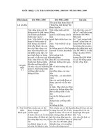
5.1 Description
5.1.1 General
The axial plane cross-section of a standard orifice plate is shown in Figure 1.
The letters given in the following text refer to the corresponding references in Figure 1.
5.1.2 General shape
5.1.2.1
The part of the plate inside the pipe shall be circular and concentric with the pipe centreline. The
faces of the plate shall always be flat and parallel.
5.1.2.2
Unless otherwise stated, the following requirements apply only to that part of the plate located
within the pipe.
SAGAWEB pour : TECHNIP FRANCE le 20/1/2004 - 9:49
ISO 5167-2:2003(E)
© ISO 2003 — All rights reserved
3
5.1.2.3 Care shall be taken in the design of the orifice plate and its installation to ensure that plastic
buckling and elastic deformation of the plate, due to the magnitude of the differential pressure or of any other
stress, do not cause the slope of the straight line defined in 5.1.3.1 to exceed 1 % under working conditions.
NOTE Further information is given in 8.1.1.3 of ISO/TR 9464:1998.
Key
1 upstream face A
2 downstream face B
a
Direction of flow.
Figure 1 — Standard orifice plate
5.1.3 Upstream face A
5.1.3.1 The upstream face A of the plate shall be flat when the plate is installed in the pipe with zero
differential pressure across it. Provided that it can be shown that the method of mounting does not distort the
plate, this flatness may be measured with the plate removed from the pipe. Under these circumstances, the
plate may be considered to be flat when the maximum gap between the plate and a straight edge of length D
laid across any diameter of the plate (see Figure 2) is less than 0,005(D – d)/2, i.e. the slope is less than
0,5 % when the orifice plate is examined prior to insertion into the meter line. As can be seen from Figure 2,
the critical area is in the vicinity of the orifice bore. The uncertainty requirements for this dimension can be met
using feeler gauges.
SAGAWEB pour : TECHNIP FRANCE le 20/1/2004 - 9:49
ISO 5167-2:2003(E)
4
© ISO 2003 — All rights reserved
Key
1 orifice plate outside diameter
2 pipe inside diameter (D)
3 straight edge
4 orifice
5 departure from flatness (measured at edge of orifice)
Figure 2 — Orifice plate-flatness measurement
5.1.3.2 The upstream face of the orifice plate shall have a roughness criterion Ra < 10
−4
d within a circle
of diameter not less than D and which is concentric with the orifice. In all cases, the roughness of the
upstream face of the orifice plate shall not be such that it affects the edge sharpness measurement. If, under
working conditions, the plate does not fulfil the specified conditions, it shall be repolished or cleaned to a
diameter of at least D.
5.1.3.3 Where possible, it is useful to provide a distinctive mark which is visible even when the orifice
plate is installed to show that the upstream face of the orifice plate is correctly installed relative to the direction
of flow.
5.1.4 Downstream face B
5.1.4.1 The downstream face B shall be flat and parallel with the upstream face (see also 5.1.5.4).
5.1.4.2 Although it may be convenient to manufacture the orifice plate with the same surface finish on
each face, it is unnecessary to provide the same high quality finish for the downstream face as for the
upstream face (see Reference [1]; but also see 5.1.9).
5.1.4.3 The flatness and surface condition of the downstream face may be judged by visual inspection.
5.1.5 Thicknesses E and e
5.1.5.1 The thickness e of the orifice shall be between 0,005D and 0,02D.
5.1.5.2 The difference between the values of e measured at any point on the orifice shall not be greater
than 0,001D.
5.1.5.3 The thickness E of the plate shall be between e and 0,05D.
However, when 50 mm u D u 64 mm, a thickness E up to 3,2 mm is acceptable.
It shall also meet the requirements of 5.1.2.3.
5.1.5.4 If D W 200 mm, the difference between the values of E measured at any point of the plate shall
not be greater than 0,001D. If D < 200 mm, the difference between the values of E measured at any point of
the plate shall not be greater than 0,2 mm.
SAGAWEB pour : TECHNIP FRANCE le 20/1/2004 - 9:49
ISO 5167-2:2003(E)
© ISO 2003 — All rights reserved
5
5.1.6 Angle of bevel
α
5.1.6.1 If the thickness E of the plate exceeds the thickness e of the orifice, the plate shall be bevelled on
the downstream side. The bevelled surface shall be well finished.
5.1.6.2 The angle of bevel
α
shall be 45° ± 15°.
5.1.7 Edges G, H and I
5.1.7.1 The upstream edge G shall not have wire-edges or burrs.
5.1.7.2 The upstream edge G shall be sharp. It is considered so if the edge radius is not greater than
0,000 4d.
If d W 25 mm, this requirement can generally be considered as satisfied by visual inspection, by checking that
the edge does not reflect a beam of light when viewed with the naked eye.
If d < 25 mm, visual inspection is not sufficient.
If there is any doubt as to whether this requirement is met, the edge radius shall be measured.
5.1.7.3 The upstream edge shall be square; it is considered to be so when the angle between the orifice
bore and the upstream face of the orifice plate is 90° ± 0,3°. The orifice bore is the region of the orifice plate
between edges G and H.
5.1.7.4 The downstream edges H and I are within the separated flow region and hence the requirements
for their quality are less stringent than those for edge G. This being the case, small defects (for example, a
single nick) are acceptable.
5.1.8 Diameter of orifice d
5.1.8.1 The diameter d shall in all cases be greater than or equal to 12,5 mm. The diameter ratio,
β
= d/D,
shall be always greater than or equal to 0,10 and less than or equal to 0,75.
Within these limits, the value of
β
may be chosen by the user.
5.1.8.2 The value d of the diameter of the orifice shall be taken as the mean of the measurements of at
least four diameters at approximately equal angles to each other. Care shall be taken that the edge and bore
are not damaged when making these measurements.
5.1.8.3 The orifice shall be cylindrical.
No diameter shall differ by more than 0,05 % from the value of the mean diameter. This requirement is
deemed to be satisfied when the difference in the length of any of the measured diameters complies with the
said requirement in respect of the mean of the measured diameters. In all cases, the roughness of the orifice
bore cylindrical section shall not be such that it affects the edge sharpness measurement.
5.1.9 Bidirectional plates
5.1.9.1 If the orifice plate is intended to be used for measuring reverse flows, the following requirements
shall be fulfilled:
a) the plate shall not be bevelled;
b) the two faces shall comply with the specifications for the upstream face given in 5.1.3;
SAGAWEB pour : TECHNIP FRANCE le 20/1/2004 - 9:49
ISO 5167-2:2003(E)
6
© ISO 2003 — All rights reserved
c) the thickness E of the plate shall be equal to the thickness e of the orifice specified in 5.1.5; consequently,
it may be necessary to limit the differential pressure to prevent plate distortion (see 5.1.2.3);
d) the two edges of the orifice shall comply with the specifications for the upstream edge specified in 5.1.7.
5.1.9.2 Furthermore, for orifice plates with D and D/2 tappings (see 5.2), two sets of upstream and
downstream pressure taps shall be provided and used according to the direction of the flow.
5.1.10 Material and manufacture
The plate may be manufactured from any material and in any way, provided that it is and remains in
accordance with the foregoing description during the flow measurements.
5.2 Pressure tappings
5.2.1 General
For each orifice plate, at least one upstream pressure tapping and one downstream pressure tapping shall be
installed in one or other of the standard locations, i.e. as D and D/2, flange or corner tappings.
A single orifice plate may be used with several sets of pressure tappings suitable for different types of
standard orifice meters, but to avoid mutual interference, several tappings on the same side of the orifice plate
shall be offset by at least 30°.
The location of the pressure tappings characterizes the type of standard orifice meter.
5.2.2 Orifice plate with D and D/2 tappings or flange tappings
5.2.2.1 The spacing l of a pressure tapping is the distance between the centreline of the pressure tapping
and the plane of a specified face of the orifice plate. When installing the pressure tappings, due account shall
be taken of the thickness of the gaskets and/or sealing material.
5.2.2.2 For orifice plates with D and D/2 tappings (see Figure 3), the spacing l
1
of the upstream pressure
tapping is nominally equal to D, but may be between 0,9D and 1,1D without altering the discharge coefficient.
The spacing l
2
of the downstream pressure tapping is nominally equal to 0,5D but may be between the
following values without altering the discharge coefficient:
between 0,48D and 0,52D when
β
u 0,6;
between 0,49D and 0,51D when
β
> 0,6.
Both l
1
and l
2
spacings are measured from the upstream face of the orifice plate.
5.2.2.3 For orifice plates with flange tappings (see Figure 3), the spacing l
1
of the upstream pressure
tapping is nominally 25,4 mm and is measured from the upstream face of the orifice plate.
The spacing l'
2
of the downstream pressure tapping is nominally 25,4 mm and is measured from the
downstream face of the orifice plate.
These upstream and downstream spacings l
1
and l'
2
may be within the following ranges without altering the
discharge coefficient:
25,4 mm ± 0,5 mm when
β
> 0,6 and D < 150 mm;
25,4 mm ± 1 mm in all other cases, i.e.
β
u 0,6, or
β
> 0,6, but 150 mm u D u 1 000 mm.
SAGAWEB pour : TECHNIP FRANCE le 20/1/2004 - 9:49
ISO 5167-2:2003(E)
© ISO 2003 — All rights reserved
7
5.2.2.4 The centreline of the tapping shall meet the pipe centreline at an angle as near to 90° as possible,
but in every case within 3° of the perpendicular.
5.2.2.5 At the point of break-through, the hole shall be circular. The edges shall be flush with the internal
surface of the pipe wall and as sharp as possible. To ensure the elimination of all burrs or wire edges at the
inner edge, rounding is permitted but shall be kept as small as possible and, where it can be measured, its
radius shall be less than one-tenth of the pressure tapping diameter. No irregularity shall appear inside the
connecting hole, on the edges of the hole drilled in the pipe wall or on the pipe wall close to the pressure
tapping.
5.2.2.6 Conformity of the pressure tappings with the requirements specified in 5.2.2.4 and 5.2.2.5 may be
judged by visual inspection.
5.2.2.7 The diameter of pressure tappings shall be less than 0,13D and less than 13 mm.
No restriction is placed on the minimum diameter, which is determined in practice by the need to prevent
accidental blockage and to give satisfactory dynamic performance. The upstream and downstream tappings
shall have the same diameter.
5.2.2.8 The pressure tappings shall be circular and cylindrical over a length of at least 2,5 times the
internal diameter of the tapping, measured from the inner wall of the pipeline.
5.2.2.9 The centrelines of the pressure tappings may be located in any axial plane of the pipeline.
5.2.2.10 The axis of the upstream tapping and that of the downstream tapping may be located in different
axial planes, but are normally located in the same axial plane.
Key
1 D and D/2 pressure tappings
2 flange tappings
a
Direction of flow.
b
l
1
= D ± 0,1D
c
l
2
= 0,5D ± 0,02D for
b
u 0,6
0,5D ± 0,01D for
b
> 0,6
d
l
1
= l¢
2
= (25,4 ± 0,5) mm for
b
> 0,6 and D < 150 mm
(25,4 ± 1) mm for
b
u 0,6
(25,4 ± 1) mm for
b
> 0,6 and 150 mm u D u 1 000 mm
Figure 3 — Spacing of pressure tappings for orifice plates with D and D/2 tappings or flange tappings
SAGAWEB pour : TECHNIP FRANCE le 20/1/2004 - 9:49
ISO 5167-2:2003(E)
8
© ISO 2003 — All rights reserved
5.2.3 Orifice plate with corner tappings (see Figure 4)
5.2.3.1 The spacing between the centrelines of the tappings and the respective faces of the plate is equal
to half the diameter or to half the width of the tappings themselves, so that the tapping holes break through the
wall flush with the faces of the plate (see also 5.2.3.5).
5.2.3.2 The pressure tappings may be either single tappings or annular slots. Both types of tappings may
be located either in the pipe or its flanges or in carrier rings as shown in Figure 4.
Key
1 carrier ring with annular slot f = thickness of the slot
2 individual tappings c = length of upstream ring
3 pressure tappings c' = length of the downstream ring
4 carrier ring b = diameter of the carrier ring
5 orifice plate a = width of annular slot or diameter of single tapping
s = distance from upstream step to carrier ring
a
Direction of flow. g, h = dimensions of the annular chamber
∅j = chamber tapping diameter
Figure 4 — Corner tappings
SAGAWEB pour : TECHNIP FRANCE le 20/1/2004 - 9:49
ISO 5167-2:2003(E)
© ISO 2003 — All rights reserved
9
5.2.3.3 The diameter a of a single tapping and the width a of annular slots are specified below. The
minimum diameter is determined in practice by the need to prevent accidental blockage and to give
satisfactory dynamic performance.
For clean fluids and vapours:
for
β
u 0,65: 0,005D u a u 0,03D;
for
β
> 0,65: 0,01D u a u 0,02D.
If D < 100 mm, a value of a up to 2 mm is acceptable for any
β
.
For any values of
β
for clean fluids: 1 mm u a u 10 mm;
for vapours, in the case of annular chambers: 1 mm u a u 10 mm;
for vapours and for liquefied gases, in the case of single tappings: 4 mm u a u 10 mm.
5.2.3.4 The annular slots usually break through the pipe over the entire perimeter, with no break in
continuity. If not, each annular chamber shall connect with the inside of the pipe by at least four openings, the
axes of which are at equal angles to one another and the individual opening area of which is at least 12 mm
2
.
5.2.3.5 If individual pressure tappings, as shown in Figure 4, are used, the centreline of the tappings shall
meet the centreline of the pipe at an angle as near to 90° as possible.
If there are several individual pressure tappings in the same upstream or downstream plane, their centrelines
shall form equal angles with each other. The diameters of individual pressure tappings are specified in 5.2.3.3.
The pressure tappings shall be circular and cylindrical over a length of at least 2,5 times the internal diameter
of the tappings measured from the inner wall of the pipeline.
The upstream and downstream pressure tappings shall have the same diameter.
5.2.3.6 The internal diameter b of the carrier rings shall be greater than or equal to the diameter D of the
pipe, to ensure that they do not protrude into the pipe, but shall be less than or equal to 1,04D. Moreover, the
following condition shall be met:
4
0,1
100
0,1 2,3
bD c
DD
β
−
×× <
+
(3)
The lengths c and c' of the upstream and downstream rings (see Figure 4) shall not be greater than 0,5D.
The thickness f of the slot shall be greater than or equal to twice the width a of the annular slot. The area of
the cross-section of the annular chamber, gh, shall be greater than or equal to half the total area of the
opening connecting this chamber to the inside of the pipe.
5.2.3.7
All surfaces of the ring that are in contact with the measured fluid shall be clean and shall have a
well-machined finish. The surface finish shall meet the pipe roughness requirements (see 5.3.1).
5.2.3.8
The pressure tappings connecting the annular chambers to the secondary devices are pipe-wall
tappings, circular at the point of break-through and with a diameter j between 4 mm and 10 mm (see 5.2.2.5).
5.2.3.9
The upstream and downstream carrier rings need not necessarily be symmetrical in relation to
each other, but they shall both conform with the preceding requirements.
SAGAWEB pour : TECHNIP FRANCE le 20/1/2004 - 9:49
ISO 5167-2:2003(E)
10
© ISO 2003 — All rights reserved
5.2.3.10 The diameter of the pipe shall be measured as specified in 6.4.2, the carrier ring being regarded
as part of the primary device. This also applies to the distance requirement given in 6.4.4 so that s shall be
measured from the upstream edge of the recess formed by the carrier ring.
5.3 Coefficients and corresponding uncertainties of orifice plates
5.3.1 Limits of use
Standard orifice plates shall only be used in accordance with this part of ISO 5167 under the following
conditions.
For orifice plates with corner or with D and D/2 pressure tappings:
d W 12,5 mm;
50 mm u D u 1 000 mm;
0,1 u
β
u 0,75;
Re
D
W 5 000 for 0,1 u
β
u 0,56;
Re
D
W 16 000
β
2
for
β
> 0,56.
For orifice plates with flange tappings:
d W 12,5 mm;
50 mm u D u 1 000 mm;
0,1 u
β
u 0,75.
Both Re
D
W 5 000 and Re
D
W 170
β
2
D
where D is expressed in millimetres.
The pipe internal roughness shall satisfy the following specification if the uncertainty values in this part of
ISO 5167 are to be met, i.e. the value of the arithmetical mean deviation of the roughness profile, Ra, shall be
such that 10
4
Ra/D is less than the maximum value given in Table 1 and greater than the minimum value given
in Table 2. The discharge coefficient equation (see 5.3.2.1) was determined from a database collected using
pipes whose roughness is known; the limits on Ra/D were determined so that the shift in discharge coefficient
due to using a pipe of a different roughness should not be so great that the uncertainty value in 5.3.3.1 is no
longer met. Information regarding pipe roughness may be found in 7.1.5 of ISO 5167-1:2003. The work on
which Tables 1 and 2 are based is described in the references [2] to [4] in the Bibliography.
Table 1 — Maximum value of 10
4
Ra/D
Re
D
β
u 10
4
3 × 10
4
10
5
3 × 10
5
10
6
3 × 10
6
10
7
3 × 10
7
10
8
u 0,20 15 15 15 15 15 15 15 15 15
0,30 15 15 15 15 15 15 15 14 13
0,40 15 15 10 7,2 5,2 4,1 3,5 3,1 2,7
0,50 11 7,7 4,9 3,3 2,2 1,6 1,3 1,1 0,9
0,60 5,6 4,0 2,5 1,6 1,0 0,7 0,6 0,5 0,4
W 0,65 4,2 3,0 1,9 1,2 0,8 0,6 0,4 0,3 0,3
SAGAWEB pour : TECHNIP FRANCE le 20/1/2004 - 9:49
ISO 5167-2:2003(E)
© ISO 2003 — All rights reserved
11
Table 2 — Minimum value of 10
4
Ra/D (where one is required)
Re
D
β
u 3 × 10
6
10
7
3 × 10
7
10
8
u 0,50 0,0 0,0 0,0 0,0
0,60 0,0 0,0 0,003 0,004
W 0,65 0,0 0,013 0,016 0,012
The roughness shall meet requirements given in Tables 1 and 2 for 10D upstream of the orifice plate. The
roughness requirements relate to the orifice fitting and the upstream pipework. The downstream roughness is
not as critical.
For example, the requirements of this section are satisfied in either of the following cases:
1 µm u Ra u 6 µm, D W 150 mm, β u 0,6 and Re
D
u 5 × 10
7
;
1,5 µm u Ra u 6 µm, D W 150 mm, β > 0,6 and Re
D
u 1,5 × 10
7
.
Where D is less than 150 mm, it is necessary to calculate the maximum and minimum values of Ra using
Tables 1 and 2.
5.3.2 Coefficients
5.3.2.1 Discharge coefficient, C
The discharge coefficient, C, is given by the Reader-Harris/Gallagher (1998) equation
[5]
:
0,7 0,3
66
28 3,5
10 10
0,596 1 0,026 1 0,216 0,000 521 (0,018 8 0,006 3 )
DD
C A
Re Re
β
ββ β
=+ − + + +
11
4
1,1
-10 -7
1, 3
22
4
(0,043 0,080e 0,123e )(1 0,11 ) 0,031( 0,8 )
1
LL
AMM
β
β
β
′′
++ − − − −
−
(4)
Where D < 71,12 mm (2,8 in), the following term shall be added to Equation (4):
0,011(0,75 ) 2,8
25,4
D
β
+−−
In these equations
β
(= d/D) is the diameter ratio, with the diameters d and D expressed in millimetres;
Re
D
is the Reynolds number calculated with respect to D;
L
1
(= l
1
/D) is the quotient of the distance of the upstream tapping from the
upstream
face of the plate
and the pipe diameter; and
L'
2
(
=
l'
2
/D) is the quotient of the distance of the downstream tapping from the
downstream
face of the
plate and the pipe diameter (L'
2
denotes the reference of the downstream spacing from the
downstream
face, while L
2
would denote the reference of the downstream spacing from the
upstream
face);
2
2
2
1
L'
M'
β
=
−
SAGAWEB pour : TECHNIP FRANCE le 20/1/2004 - 9:49
ISO 5167-2:2003(E)
12
© ISO 2003 — All rights reserved
0,8
19 000
D
A
Re
β
=
The values of
L
1
and
L'
2
to be used in this equation, when the spacings are in accordance with the
requirements of 5.2.2.2, 5.2.2.3 or 5.2.3, are as follows:
for corner tappings:
L
1
=
L'
2
= 0
for
D
and
D
/2 tappings:
L
1
= 1
L'
2
= 0,47
for flange tappings:
12
25,4
LL'
D
==
where
D
is expressed in millimetres.
The Reader-Harris/Gallagher (1998) equation, Equation (4), is only valid for the tapping arrangements
specified in 5.2.2 or 5.2.3. In particular, it is not permitted to enter into the equation pairs of values of
L
1
and
L'
2
which do not match one of the three standardized tapping arrangements.
Equation (4), as well as the uncertainties given in 5.3.3, is only valid when the measurement meets all the
limits of use specified in 5.3.1 and the general installation requirements specified in Clause 6 and in
ISO 5167-1.
Values of
C
as a function of
β
,
Re
D
and
D
are given for convenience in Tables A.1 to A.11. These values are
not intended for precise interpolation. Extrapolation is not permitted.
5.3.2.2 Expansibility [expansion] factor,
ε
For the three types of tapping arrangement, the empirical formula
[6]
for computing the expansibility
[expansion] factor,
ε
, is as follows:
()
1/
48
2
1
1 0,351 0,256 0,93 1
p
p
κ
εββ
=− + + −
(5)
Equation (5) is applicable only within the range of the limits of use specified in 5.3.1.
Test results for the determination of
ε
are only known for air, steam and natural gas. However, there is no
known objection to using Equation (5) for other gases and vapours of which the isentropic exponent is known.
Nonetheless, Equation (5) is applicable only if p
2
/p
1
W
0,75.
Values of the expansibility [expansion] factor as a function of the isentropic exponent, the pressure ratio and
the diameter ratio are given for convenience in Table A.12. These values are not intended for precise
interpolation. Extrapolation is not permitted.
SAGAWEB pour : TECHNIP FRANCE le 20/1/2004 - 9:49
ISO 5167-2:2003(E)
© ISO 2003 — All rights reserved
13
5.3.3 Uncertainties
5.3.3.1 Uncertainty of discharge coefficient C
For all three types of tappings, when
β
, D, Re
D
and Ra/D are assumed to be known without error, the relative
uncertainty of the value of C is equal to:
(0,7 –
β
) % for 0,1 u
β
< 0,2;
0,5 % for 0,2 u
β
u 0,6;
(1,667
β
– 0,5) % for 0,6 <
β
u 0,75.
If D < 71,12 mm (2,8 in), the following relative uncertainty should be added arithmetically to the above values:
0,9 (0,75 ) 2,8 %
25,4
D
β
+−−
If
β
> 0,5 and Re
D
< 10 000, the following relative uncertainty should be added arithmetically to the above
values:
0, 5 %+
5.3.3.2 Uncertainty of expansibility [expansion] factor
ε
When
β
,
∆
p
/
p
1
and
κ
are assumed to be known without error, the relative uncertainty of the value of
ε
is equal
to
1
3, 5 %
p
p
κ
∆
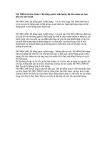
5.4 Pressure loss, ∆
ϖ
5.4.1
The pressure loss, ∆
ϖ
, for the orifice plates described in this part of ISO 5167 is approximately related
to the differential pressure ∆p by Equation (7)
42 2
42 2
1(1)
1(1)
CC
p
CC
ββ
ϖ
ββ
−−−
∆= ∆
−−+
(7)
This pressure loss is the difference in static pressure between the pressure measured at the wall on the
upstream side of the orifice plate, at a section where the influence of the approach impact pressure adjacent
to the plate is still negligible (approximately D upstream of the orifice plate), and that measured on the
downstream side of the orifice plate, where the static pressure recovery by expansion of the jet may be
considered as just completed (approximately 6D downstream of the orifice plate). Figure 5 shows the pressure
profile through an orifice metering system.
5.4.2
Another approximate value of ∆
ϖ
/∆p is
1,9
1
p
ϖ
β
∆
=−
∆
SAGAWEB pour : TECHNIP FRANCE le 20/1/2004 - 9:49
ISO 5167-2:2003(E)
14
© ISO 2003 — All rights reserved
5.4.3 The pressure loss coefficient, K, for the orifice plate is (see Reference [7])
2
42
2
1(1)
1
C
K
C
β
β
−−
=−
where K is defined by the following equation:
2
1
1
2
K
V
ϖ
ρ
∆
=
Key
1 plane of upstream pressure tappings
2 plane of downstream pressure tappings
3 plane of “vena contracta” (highest velocities)
4 plane of temperature probe
5 secondary flow regions
6 thermometer pocket or well
7 pressure tappings
8 pressure distribution on the wall
9 mean temperature distribution
Figure 5 — Approximate profiles of flow, pressure and temperature in an orifice metering system
SAGAWEB pour : TECHNIP FRANCE le 20/1/2004 - 9:49
ISO 5167-2:2003(E)
© ISO 2003 — All rights reserved
15
6 Installation requirements
6.1 General
General installation requirements for pressure differential devices are given in Clause 7 of ISO 5167-1:— and
should be followed in conjunction with the additional specific requirements for orifice plates given in this clause.
The general requirements for flow conditions at the primary device are given in 7.3 of ISO 5167-1:—. The
requirements for use of a flow conditioner are given in 7.4 of ISO 5167-1:—. For some commonly used fittings,
as specified in Table 3, the minimum straight lengths of pipe indicated may be used and detailed requirements
are given in 6.2. However, a flow conditioner as specified in 6.3 will permit the use of a shorter upstream pipe
length; moreover, a flow conditioner shall be installed upstream of the orifice plate where sufficient straight
length to achieve the desired level of uncertainty is not available. Downstream of a header the use of a flow
conditioner is strongly recommended. Many of the lengths given in 6.2 and all lengths given in 6.3.2 are based
on data included in Reference [8] of the Bibliography. Additional work which contributed to the lengths in 6.2 is
given in References [9] and [10].
6.2 Minimum upstream and downstream straight lengths for installation between various
fittings and the orifice plate
6.2.1 The minimum straight lengths of pipe required upstream and downstream of the orifice plate for the
specified fittings in the installation without flow conditioners are given in Table 3.
6.2.2 When a flow conditioner is not used, the lengths specified in Table 3 shall be regarded as the
minimum values. For research and calibration work in particular, it is recommended that the upstream values
specified in Table 3 be increased by at least a factor of 2 to minimize the measurement uncertainty.
6.2.3 When the straight lengths used are equal to or longer than the values specified in Columns A of
Table 3 for “zero additional uncertainty”, it is not necessary to increase the uncertainty in discharge coefficient
to take account of the effect of the particular installation.
6.2.4 When the upstream or downstream straight length is shorter than the value corresponding to “zero
additional uncertainty” shown in Columns A and either equal to or greater than the “0,5 % additional
uncertainty” value shown in Columns B of Table 3 for a given fitting, an additional uncertainty of 0,5 % shall be
added arithmetically to the uncertainty in the discharge coefficient.
6.2.5 This part of ISO 5167 cannot be used to predict the value of any additional uncertainty when either
a) straight lengths shorter than the “0,5 % additional uncertainty” values specified in Columns B of Table 3
are used; or
b) both the upstream and downstream straight lengths are shorter than the “zero additional uncertainty”
values specified in Columns A of Table 3.
6.2.6 The valve shown in Table 3 shall be set fully open during the flow measurement process. It is
recommended that control of the flowrate be achieved by valves located downstream of the orifice plate.
Isolating valves located upstream of the orifice plate shall be set fully open, and these valves shall be full bore.
The valve should be fitted with stops for alignment of the ball in the open position. The valve shown in Table 3
is one which is of the same nominal diameter as the upstream pipe, but whose bore diameter is such that a
diameter step is larger than that permitted in 6.4.3.
6.2.7 In the metering system, upstream valves which are match bored to the adjacent pipework and are
designed in such a manner that in the fully opened condition there are no steps greater than those permitted
in 6.4.3, can be regarded as part of the metering pipework length and do not need to have added lengths as in
Table 3 provided that when flow is being measured they are fully open.
SAGAWEB pour : TECHNIP FRANCE le 20/1/2004 - 9:49
ISO 5167-2:2003(E)
16
© ISO 2003 — All rights reserved
Table 3 — Required straight lengths between orifice plates and fittings without flow conditioners
Values expressed as multiples of internal diameter, D
Upstream (inlet) side of orifice plate
Down-
stream
(outlet) side
of the
orifice plate
Diam-
eter
ratio
β
Single 90°
bend
Two 90°
bends in
any plane
(S > 30D)
a
Two 90°
bends in
the same
plane:
S-configur-
ation
(30D W S >
10D)
a
Two 90°
bends in
the same
plane:
S-configur-
ation
(10D W S)
a
Two 90°
bends in
perpen-
dicular
planes
(30D W S W
5D)
a
Two 90°
bends in
perpen-
dicular
planes
(5D > S)
a, b
Single 90°
tee with or
without an
extension
Mitre 90°
bend
Single 45°
bend
Two 45°
bends in
the same
plane:
S-configur-
ation
(S W 2D)
a
Concentric
reducer
2D to D
over a
length of
1,5D to 3D
Concentric
expander
0,5D to D
over a
length of
D to 2D
Full bore
ball valve
or gate
valve fully
open
Abrupt
symmetrical
reduction
Ther-
mometer
or well
c
of diameter
u 0,03D
d
Fittings
(columns 2
to 11) and
the densi-
tometer
1 2 3 4 5 6 7 8 9 10 11 12 13 14
— A
e
B
f
A
e
B
f
A
e
B
f
A
e
B
f
A
e
B
f
A
e
B
f
A
e
B
f
A
e
B
f
A
e
B
f
A
e
B
f
A
e
B
f
A
e
B
f
A
e
B
f
u 0,20 6 3 10
g
10
g
19 18 34 17 3
g
7
g
5
g
6
g
12 6 30 15 5 3 4 2
0,40 16 3 10
g
10
g
44 18 50 25 9 3 30 9 5
g
12 8 12 6 30 15 5 3 6 3
0,50 22 9 18 10 22 10 44 18 75 34 19 9 30 18 8 5 20 9 12 6 30 15 5 3 6 3
0,60 42 13 30 18 42 18 44 18 65
h
25 29 18 30 18 9 5 26 11 14 7 30 15 5 3 7 3,5
0,67 44 20 44 18 44 20 44 20 60 18 36 18 44 18 12 6 28 14 18 9 30 15 5 3 7 3,5
0,75 44 20 44 18 44 22 44 20 75 18 44 18 44 18 13 8 36 18 24 12 30 15 5 3 8 4
NOTE 1 The minimum straight lengths required are the lengths between various fittings located upstream or downstream of the orifice plate and the orifice plate itself. Straight lengths shall be measured from the
downstream end of the curved portion of the nearest (or only) bend or of the tee or the downstream end of the curved or conical portion of the reducer or the expander.
NOTE 2 Most of the bends on which the lengths in this table are based had a radius of curvature equal to 1,5D.
a
S is the separation between the two bends measured from the downstream end of the curved portion of the upstream bend to the upstream end of the curved portion of the downstream bend.
b
This is not a good upstream installation; a flow conditioner should be used where possible.
c
The installation of thermometer pockets or wells will not alter the required minimum upstream straight lengths for the other fittings.
d
A thermometer pocket or well of diameter between 0,03D and 0,13D may be installed provided that the values in Columns A and B are increased to 20 and 10 respectively. Such an installation is not, however,
recommended.
e
Column A for each fitting gives lengths corresponding to “zero additional uncertainty” values (see 6.2.3).
f
Column B for each fitting gives lengths corresponding to “0,5 % additional uncertainty” values (see 6.2.4).
g
The straight length in Column A gives zero additional uncertainty; data are not available for shorter straight lengths which could be used to give the required straight lengths for Column B.
h
95D is required for Re
D
> 2 × 10
6
if S < 2D.
SAGAWEB pour : TECHNIP FRANCE le 20/1/2004 - 9:49