Logic kỹ thuật số thử nghiệm và mô phỏng P10
Bạn đang xem bản rút gọn của tài liệu. Xem và tải ngay bản đầy đủ của tài liệu tại đây (221.39 KB, 38 trang )
513
Digital Logic Testing and Simulation
,
Second Edition
, by Alexander Miczo
ISBN 0-471-43995-9 Copyright © 2003 John Wiley & Sons, Inc.
CHAPTER 10
Memory Test
10.1 INTRODUCTION
Memory is pervasive in digital products. Consider, for example, the personal com-
puter (PC). It has main memory, video memory, translation ROMs, shadow ROMs,
scratchpad memory, hard disk, floppy disk, CDROM, and various other kinds of
storage distributed throughout. In addition, the die that contains the microprocessor
may also contain one or more levels of cache.
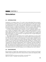
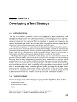
A typical PC is depicted in the block diagram of Figure 10.1. It is basically a
memory hierarchy connected by several buses and adapters and controlled by a
CPU. The purpose for much of the hierarchy is to combine two or more storage sys-
tems with divergent capacities, speeds, and costs such that the combined system has
almost the speed of the smaller, faster, more expensive memory at almost the cost,
speed, and storage capacity of the larger, slower, less expensive memory. Clearly,
not all storage devices are part of this hierarchy. The CDROM may be used to
deliver programs and/or data to an end user, and video memory is dedicated to the
display console. The central processing unit (CPU) accesses many of these auxiliary
memory devices through a peripheral component interconnect (PCI) bus, which reg-
ulates the flow of data through the system.
Unlike the random logic that has been considered up to this point, memory storage
devices are characterized by a high degree of regularity. For example, a semiconductor
memory is organized as an array of cells, while storage on a hard drive is organized
into cylinders. This regularity of semiconductor memories permits much greater pack-
ing of transistors on die. For example, in the PowerPC MPC750, memory accounts for
85% of the transistors but only 44% of the die area.
1
In the Alpha 21164, 80% of the
9.6 million transistors are used for three on-chip caches, but the remaining 20% of the
transistors occupy a majority of the physical die area.
2
The various storage devices in
Figure 10.1 employ different kinds of circuits for storing and retrieving data, and dif-
ferent kinds of media for retaining data, hence they have unique failure mechanisms,
requiring different test strategies. These memories may also employ varying levels of
redundancy to detect and/or correct errors during operation.
514
MEMORY TEST
Figure 10.1
Memory distribution in a typical PC architecture.
10.2 SEMICONDUCTOR MEMORY ORGANIZATION
Because semiconductor memories are characterized by a high degree of regularity, it
is easy to devise algorithms to test them. However, because of the growing capacity
of memories, many of the tests will run for unacceptably long periods of time. A sig-
nificant problem then, when testing memories, is to identify the kinds of faults that
are most likely to occur and determine the most efficient tests for those faults.
Semiconductor memories can be characterized according to the following
properties:
Serial or random access
Volatile or nonvolatile
Static or dynamic
Destructive or nondestructive readout.
Serial
access memories are those in which data are accessed in a fixed, predeter-
mined sequence. Magnetic tape units are an example of serial access. To read a
record it is necessary to read the entire tape up to the point where the desired data
exists. By way of contrast, a
random
access memory (RAM) permits reading of data
at any specific location without first reading other data. When performing a read of a
FIFO (first-in, first-out) memory, the first location stored is the first to be read out.
These memories act as buffers when transferring data between functional units with
different data rates. A stack in a computer, often used to save data and return
addresses, is an example of a LIFO (last-in, first-out) memory. The last data pushed
onto the stack is the first data to become available when the stack contents are
popped from the stack.
CPU
Memory
Bus
Local
Bus
Cache
controller
PCI
bridge
Main
memory
Motion
video
peripheral
Video
memory
SCSI
Host bus
adapter
LAN
adapter
ISA/EISA
bridge
PCI Bus
LAN
CD
ROM
Disk
Tape
Expansion bus
Graphics
adapter
Video
frame
buffer
Bus
master
I/O
slave
Memory
slave
SEMICONDUCTOR MEMORY ORGANIZATION
515
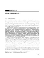
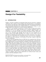
Figure 10.2
Dynamic memory cell.
Memories can be categorized according to whether or not they can retain infor-
mation when power is removed. A
nonvolatile
memory can retain information when
power is removed. Examples of nonvolatile memories include magnetic cores, mag-
netic tapes, disks, MROMs, EPROMS, EEPROMS, and flash memories.
Volatile
memory devices lose information when power is removed.
Volatile memories can be further broken down into static and dynamic memories. A
static
memory retains information as long as power is applied, while a
dynamic
mem-
ory can lose information even when power is continuously applied. Static RAMs
(SRAMs) are flip-flops that, with their two stable states, can remain in a given state
indefinitely, without need for refresh, as long as power is applied; that is, they are static
but volatile. The dynamic RAM (DRAM), illustrated in Figure 10.2, is an example of a
dynamic memory. The cell is chosen if decoding the memory address causes its word-
line to be selected. It is basically a capacitor that can either be discharged onto the bit-
line or that can be recharged from the bit-line. Since it is a capacitor, the charge can
leak away over time. The memory system must employ refresh circuitry that periodi-
cally reads the cells and writes back a suitably amplified version of the signal.
If the contents of a memory device are destroyed by a read operation, it is classi-
fied as a
destructive readout
(DRO); otherwise it is a
nondestructive readout
(NDRO) device. DRAMs must be refreshed when their contents are read out, since a
read causes the capacitor to discharge.
Programmable read-only memories (PROMs) are slightly more complicated to
characterize. They are static and nonvolatile. Mask programmable ROMs and fuse
programmable ROMs are programmed once and thereafter can only be read.
EPROMs (erasable PROMs) can be erased by means of ultraviolet light, which
involves physically removing them from the system in which they are installed. For
all practical purposes, they are programmed only once because it is quite inconve-
nient to erase and reprogram them, unless they are being used to emulate a new
design for the purposes of debugging that design.
EEPROMs (electrically erasable PROMs) can be reprogrammed after being
installed in a system, but their response time is slower than DRAMs or SRAMs;
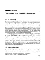
hence they are confined to applications where nonvolatility is required. Flash memo-
ries are structurally almost identical to EPROMs, but they can be reprogrammed in a
system and are more dense than EEPROMs. However, EEPROMs can be pro-
grammed a bit at a time, whereas flash memories are erased a block at a time before
being reprogrammed. The Venn diagram in Figure 10.3 illustrates this distribution of
properties among the various kinds of semiconductor memories.
3
read/write select
Bit-line
Data bit
Word-line
516
MEMORY TEST
Figure 10.3
Semiconductor memory properties.
Semiconductor memories usually employ an organization called 2-D. In this orga-
nization a 2
m
×
1 memory with
m
address lines is organized into a matrix with 2
N
rows and 2
M
columns (
N + M = m
). The address lines are split into two groups such
that
N
lines go to a row decoder and
M
lines go to a column decoder. This is illus-
trated in Figure 10.4. The row decoder selects 2
N
memory cells, and the column
decoder selects one of those to be read out of or written into memory. This idealized
organization is the subject of numerous modifications whose purpose is to permit
faster operation and/or faster test. One of the more significant changes is the division
of the memory array into several smaller arrays. This reduces loading on the bit lines.
As we shall see, it also permits multiple cells to be tested simultaneously.
Figure 10.4
A semiconductor memory organization.
Dense
Non-
volatile
Re-
writable
DRAM
ROM
EPROM
EEPROM
FLASH
...
...
...
...
Row decode
Column decode
A
0
A
1
A
N
2
N
word lines
N ×M
MEMORY
ARRAY
A
N+1
A
N+2
A
N+M
...
...
Data
Data
D
in
D
out
b
0
b
0
b
1
b
1
bm bm
R/W
CS
m = 2
M
Sense Amps
MEMORY TEST PATTERNS
517
10.3 MEMORY TEST PATTERNS
In this section some classical, or legacy, memory test algorithms will be examined.
Memory test algorithms fall into two categories: functional and dynamic. A
func-
tional test
targets defects within a memory cell, as well as failures that occur when
cell contents are altered by a read or write to another cell. A
dynamic test
attempts to
find access time failures. The
All 1s
or
All 0s
tests are examples of functional tests.
These tests write 1s or 0s into all memory cells in order to detect individual cell
defects including shorts and opens. However, these tests are not effective at finding
other failure types.
A memory test pattern that tests for address nonuniqueness and other functional
faults in memories, as well as some dynamic faults, is the
GALPAT
(GALloping
PATtern), sometimes referred to as a ping-pong pattern. This pattern accesses each
address repeatedly using, at some point, every other cell as a previous address. It
starts by writing a background of zeroes into all memory cells. Then the first cell
becomes the test cell. It is complemented and read alternately with every other cell
in memory. Each succeeding cell then becomes the test cell in turn and the entire
read process is repeated. All data are complemented and the entire test is repeated. If
each read and compare is counted as one operation, then GALPAT has an execution
time proportional to 4
N
2
, where
N
is the number of cells. It is effective for finding
cell opens, shorts, address uniqueness faults, sense amplifier interaction, and access
time problems.
The following Verilog code illustrates the operation of the GALPAT test. First, a
RAM module of size “memdepth”
×
1 bit is described. The RAM model contains
code used to insert a stuck-at fault at memory location 27. The RAM model is fol-
lowed by a testbench that executes the GALPAT test. The line of code that instanti-
ates the RAM passes parameters into the RAM from the testbench in order to
override the RAM size.
module
ram(addr, datai, datao, wen, oen);
parameter
log2_memdepth = 8, memdepth = 256;
input
[log2_memdepth
−
1:0] addr;
input
datai, wen, oen;
output
datao;
reg
ramcore[memdepth
−
1:0];
reg
datao;
always
@(oen or wen or addr)
begin
if
(!oen && wen) datao = ramcore[addr];
else if
(oen) datao = 1
'
bz;
else
datao = 1
'
bx;
end
always
@(negedge wen)
begin
518
MEMORY TEST
if
(addr == 27) // inject a fault at location 27
ramcore[addr] = 1'b1;
else
ramcore[addr] = datai;
end
endmodule
module testbench;
parameter log2_memdepth = 6;
parameter memdepth = 64;
reg [log2_memdepth−1:0] addr;
reg datain, wen, oen, memval;
wire dataout;
integer e, i, j;
ram #(log2_memdepth,memdepth)
U1(addr,datain,dataout,wen, oen);
always
begin
for(e = 0; e <= 1; e = e+1)
begin
for(i = 0; i < memdepth; i = i+1)
write(e,i); // write background of e, e ∈ {0,1}
for(i = 0; i < memdepth; i = i+1)
begin
write(!e,i);
for(j = 0; j < memdepth; j = j+1)
if(j != i)
begin //check all mem. loc. except loc. i
read(memval, j);
if(memval != e)
$display("Mem. Error at loc. %d\n",j);
end // for j
read(memval,i); // loc. i should not change
if(memval != !e)
$display("Mem. Error at loc. %d\n", j);
write(e,i); // restore value at loc. i
end // for i
end // for e
$finish;
end // always
task write; // write to memory
MEMORY TEST PATTERNS
519
input data, adval;
integer adval;
begin
datain = data;
addr = adval;
#1 wen = 0; #1 wen = 1;
end
endtask
task read; // read from memory
output data;
input adval;
integer adval;
begin
addr = adval;
#1 oen = 0;
#0.5 data = dataout;
#0.5 oen = 1;
end
endtask
endmodule
Walking Pattern is similar to the GALPAT except that the test cell is read once
and then all other cells are read. To create a Walking Pattern from the GALPAT pro-
gram, omit the second read operation in the testbench. The Walking Pattern has an
execution time proportional to 2N
2
. It checks memory for cell opens and shorts and
address uniqueness.
March, like most of the algorithms, begins by writing a background of zeroes.
Then it reads the data at the first location and writes a 1 to that address. It continues
this read/write procedure sequentially with each address in memory. When the end
of memory is reached, each cell is read and changed back to zero in reverse order.
The test is then repeated using complemented data. Execution time is of order N. It
can find cell opens, shorts, address uniqueness, and some cell interactions.
Galloping Diagonal is similar to GALPAT in that a 1 is moved through memory.
However, it is moved diagonally, checking both row and column decoders simulta-
neously. It is of order 4N
3/2
. Row and column GALPATs of order 4N
3/2
also exist.
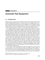
Sliding Diagonal (see Figure 10.5) writes a complete diagonal of 1s against a
background of 0s and then, after reading all memory cells, it shifts the diagonal hor-
izontally. This continues until the diagonal of 1s has passed through all memory
locations. The Diagonal test, of order N, will verify address uniqueness at a signifi-
cant speed enhancement over the Walk or GALPAT.
Checkerboard Test writes 1s and 0s into alternate memory locations in a check-
erboard pattern. After a time delay, which may be several seconds, the pattern is read
from memory. This pattern is used to evaluate data retention in static RAMs.
520
MEMORY TEST
Figure 10.5 The sliding diagonal test.
Surround Read Disturb starts by creating a background of all 0s. Then, each
cell in turn becomes the test cell. The test cell is complemented and the eight physi-
cally adjacent cells are repeatedly read. After a number of iterations the test cell is
read to determine if it has been affected by the read of its neighbors. The operation is
then repeated for a background of 1s. The intent is to find disturbances caused by
adjacent cell operations. Execution time depends on the number of read cycles but is
of the order N.
Surround Write Disturb is identical to the Surround Read Disturb except that a
write rather than a read is performed.
Write Recovery writes a background of 0s. Then the first cell is established as
the test cell. A 1 is written into the second cell and the first (test) cell is read. The
second cell is restored to 0 and the test cell is read again. This is repeated for the test
cell and every other cell. Every cell then becomes the test cell in turn. The entire
process is repeated using complemented data. This is an N
2
test that is directed at
write recovery type faults. It also detects faults that are detected by GALPAT.
Address Test writes a unique value into each memory location. Typically, this
could be the address of that memory cell; that is, the value n is written into memory
location n. After writing all memory locations, the data are read back. The purpose
of this test is to check for address uniqueness. This algorithm requires that the num-
ber of bits in each memory word equal or exceed the number of address bits.
Moving Inversions test
4
inverts a memory filled with 0s to 1s and conversely.
After initially filling the memory with 0s, a word is read. Then a single bit is
changed to a 1, and the word is read again. This is repeated until all bits in the word
are set to 1 and then repeated for every word in memory. The operation is then
reversed, setting bits to 0 and working from high memory to low memory.
For a memory with n address bits the process is repeated n times. However, on
each repetition, a different bit of the address is taken as the least significant bit for
incrementing through all possible addresses. An overflow generates an end around
carry so all addresses are generated but the method increments through addresses by
1s, 2s, 4s, and so on. For example, on the second time through, bit 1 (when regarding
bit 0 as least significant bit, LSB) is treated as the LSB so all even addresses are gen-
erated out to the end of memory. After incrementing to address 111...110, the next
address generated is address 000...001, and then all consecutive odd addresses are
1 0 0 0 0 0 0 0
0 1 0 0 0 0 0 0
0 0 1 0 0 0 0 0
0 0 0 1 0 0 0 0
0 0 0 0 1 0 0 0
0 0 0 0 0 1 0 0
0 0 0 0 0 0 1 0
0 0 0 0 0 0 0 1
MEMORY FAULTS
521
generated out to the end of memory. The pattern of memory address generation
(read the addresses vertically) for the second iteration is as follows:
0000 . . . 1111
. . .
. . .
. . .
0000 . . . 1111
0011 . . . 0011
0101 . . . 0101
0000 . . . 1111
The Moving Inversions test pattern has 12BN log
2
N patterns, where B is the number
of bits in a memory word. It detects addressing failures and cell opens and shorts. It
is also effective for checking access times.
10.4 MEMORY FAULTS
As memories grow larger, with more memory cells packed into an ever-shrinking
die area, the cost to manufacture a die remains fairly constant, while the time it takes
to apply test programs increases exponentially. It is variously estimated that the cost
to test a memory chip runs from 50% to 70% of the total cost of the finished prod-
uct.
5
The first step in reducing the cost of memory test is to understand what fault
mechanisms are most likely to occur and then develop test programs that target
those faults. With this approach, the manufacturer and the end-user can determine
their priorities, balancing cost versus DPM (defects per million) that they can toler-
ate in their applications.
A number of different failure types can occur in semiconductor memories, affect-
ing memory cell contents, cell addressing, and the time required to read out data.
Some of the more common failures include the following:
6
Cell opens or shorts
Address nonuniqueness
Cell/column/row disturb sensitivity
Sense amplifier interaction
Slow access time
Slow write recovery
Data sensitivity
Refresh sensitivity
Static data losses
Opens and shorts within semiconductor memory cells may occur because of
faulty processing, including misaligned masks or imperfect metallization. These
522
MEMORY TEST
failures are characterized by a general randomness in their nature. Opens and shorts
may occur at the chip connections to a printed circuit board. In a km × n memory
system containing km words of n bits each, and made up of memory chips of size
m × 1, a fault that occurs in bit position i of m consecutive bits is indicative of either
a totally failed chip or one in which an open or short exists between the chip and the
PCB on which it is mounted.
Address nonuniqueness results from address decoder failures that may either
cause the same memory cell to be accessed by several different addresses or several
cells may be addressed during a single access. These failures often cause some cells
to be physically inaccessible. An effective test must insure that each read or write
operation accesses one, and only one, memory cell.
Disturb sensitivity between adjacent cells or between cells in the same row or
column can result from capacitive coupling. Slow access time can be caused by slow
decoders, overloaded sense amplifiers, or an excessive capacitive charge on output
circuits. Slow write recovery may indicate a saturated sense amplifier that cannot
recover from a write operation in time to perform a subsequent read operation.
A memory cell can be affected by the contents of neighboring cells. Worse still,
the cell may be affected only by particular combinations on neighboring cells. This
problem grows more serious as the distance between neighboring cells shrinks.
Refresh sensitivity in dynamic RAMs may be induced by a combination of data
sensitivity and temperature or voltage fluctuations. Static RAM cells are normally
able to retain their state indefinitely. However, data may become lost due to leakage
current or opens in resistors or feedback paths.
Recall from Section 3.4, when discussing faults in random logic, that fault mod-
els other than the stuck-at model were examined. The one trait these models had in
common was a susceptibility to combinatorial explosion. For very small circuits, the
number of faults grew so quickly that it was simply not feasible to consider them.
Memory circuits, because of their density and the close proximity of cells to one
another, exhibit this problem of combinatorial explosion to a far greater degree.
Hence, it becomes necessary to restrict consideration to faults that are most likely to
occur.
The first step is to group the faults into three broad categories: address decoder
faults, memory array faults, and read/write logic faults. From there we use the fact,
demonstrated by Nair, Thatte, and Abraham,
7
that faults in memory addressing and
read/write logic, which includes sense amplifiers, write drivers, and other supporting
logic, can be mapped onto functionally equivalent faults in the memory array. This
makes it possible to concentrate on faults in the memory array and to develop tests
addressed at the functionality of the memory array.
First consider faults in the address decode logic. A fault may cause multiple cells
to be accessed, or no cell may be accessed, or the wrong cell may be addressed. In
the case of multiple cells being addressed, the fault may be viewed as a coupling
fault between cells. If no cell is addressed, then, depending on the logic, the
response from the read logic may appear as a stuck-at-1 or a stuck-at-0. If the wrong
cell is addressed, then, given the presence of the opposite value in that cell, it
appears as a stuck-at fault.
MEMORY FAULTS
523
A fault in the read/write logic may cause an output line to be stuck-at-0 or stuck-
at-1. In either case, the corresponding cell may be considered to be stuck-at-0 or
stuck-at-1. If there are shorts or capacitive coupling between data input or data out-
put lines, these faults can be regarded as coupling between memory cells.
Three conditions, listed below, are defined by Nair et al. in order to detect the
faults in their fault model. In the conditions, a forced transition is one that occurs as
a result of the test algorithm writing into a cell.
Condition 1. Every cell must undergo each of the following two transitions, and must
be read after each transition, before undergoing any subsequent forced transitions.
(a) a 0–1 transition and
(b) a 1–0 transition.
Condition 2. For every pair of cells (i, j), cell i must be read after cell j makes a
forced transition and before cells i and j make any further forced transitions for the
following states of cell i and transitions in cell j:
(a) cell i in state 0, cell j making a 0–1 transition,
(b) cell i in state 1, cell j making a 0–1 transition,
(c) repeat a and b with cell j making a 1–0 transition.
Condition 3. For every cell triple (i, j, k), and x, y, z ∈ {0, 1}, if the test makes a
transition in cell j from y to y
after cell i makes a transition from x to x and before cell
k in state z is read, then the test must possess another sequence where either:
(a) cell k in state z is read after an x to x
transition in cell i and before a y to
y transition in cell j, or
(b) cell k in state z
is read after a y to y transition in cell j and before an x to
x transition in cell i.
Theorem 10.1 The conditions 1 through 3 are necessary and sufficient for a test to
detect all the stuck-at and coupling faults in the memory array.
The proof of this theorem is left as an exercise for the reader. An algorithm is now
presented that addresses the faults in the fault model just described. The notation
used here is from van de Goor.
8
[⇑(W0)] Initialize to all 0s
[⇑(R0,W1); ⇓(R1)] Sequence 1
[⇑(R1,W0); ⇓(R0)] Sequence 2
[⇓(R0,W1); ⇑(R1)] Sequence 3
[⇓(R1,W0); ⇑(R0)] Sequence 4
524
MEMORY TEST
Theorem 10.2 The above algorithm is a complete test for the stated memory fault
model.
The algorithm described above is of order n, denoted O(n), where n is the size of
memory. In fact, there are 30 read and write passes through memory, so the algo-
rithm is frequently described as being of complexity 30n. In their paper, Nair et al.
point out that the GALPAT, which is O(n
2
), does not satisfy all of condition 2. They
then define a more comprehensive fault model that includes coupling faults, and
they extend the above algorithm to address those faults.
10.5 MEMORY SELF-TEST
Memory ICs keep growing larger. The cost of manufacturing these ICs remains rela-
tively constant as they grow larger, but the cost of testing them increases, because
every cell has to be tested for several different kinds of fault mechanisms. It was
pointed out in the previous section that the cost of testing these large memory ICs
often takes up more than half of the total manufacturing cost.
One of the major contributors to test cost for memory ICs is the commercial
testers that are used to test them. In addition to the growing size of memories, the
speed at which they operate also continues to increase. In order to keep up with
memory IC technology, vendors must constantly upgrade their testers, with a result-
ant increase in cost. Another problem that must be faced is the inability to access
many of the memories because they are embedded in ICs, surrounded by random
logic. Gaining access to the address, data and control pins and controlling them with
dedicated memory test algorithms is often impossible.
As a result of these growing difficulties, memory built-in self-test (MBIST) has
become an accepted way to test many memories. BIST not only has the ability to
access embedded memories, but it also has the advantage that it can be designed in
conjunction with the memory. Thus, architectural features can be incorporated into the
design to take advantage of the presence of BIST. This includes partitioning an internal
memory array into several smaller arrays that can be tested in parallel, thus signifi-
cantly reducing total test time. Note, however, that fragmentation of memories may be a
[⇑(R0,W1,W0); ⇓(R0)] Sequence 5
[⇓(R0,W1,W0); ⇑(R0)] Sequence 6
[⇑(W1)] Initialize to all 1s
[⇑(R1,W0,W1); ⇓(R1)] Sequence 7
[⇓(R1,W0,W1); ⇑(R1)] Sequence 8
Legend:
⇑—operate in ascending order W0—write 0 W1—write 1
⇓—operate in descending order R0—read 0 R1—read 1
MEMORY SELF-TEST
525
disadvantage. If a design contains many small memories, the overhead of BIST may
be prohibitive.
Another advantage of BIST is its ability to test memory within a system while it
is in operation; hence whenever the system is powered up, the memory can be tested
for defects that may have occurred since the system was last in operation. This is
critical in systems that must be failsafe, particularly as there is some concern that
with technology approaching 0.1 micron; soft errors and noise may become major
problems.
9
10.5.1 A GALPAT Implementation
A generic BIST circuit is depicted in Figure 10.6.
10
For memory test the CUT would
be the memory module. The BIST must not only generate the data, but must also
contain circuits to generate memory addresses in some predetermined order. With
minor modifications to the diagram, the same test generator could be used to gener-
ate the expected response, by way of the control logic, in addition to the test pattern
sequence. In fact, the test generator could generate data to first fill all of memory
with some desired pattern, then the same test generator could generate the expected
response simultaneously with reading memory. Depending on the algorithm imple-
mented by the test generator, this BIST will test for addressing faults as well as
memory faults.
The following synthesizable Verilog code implements a BIST circuit, together
with testbench, to perform a GALPAT test. Note that the GALPAT example in
Section 10.3 was executed by the testbench; it would be analogous to application of
GALPAT from a memory tester. The reader can experiment with the parameters to
see how the circuit behaves with different memory sizes. The circuit is easily modi-
fied to perform one of several other memory test algorithms that we will discuss sub-
sequently (see the exercises at the end of the chapter). The RAM module, not listed
here, is the same one used previously (Section 10.3). It is easily altered to model
various fault mechanisms.
Figure 10.6 Generic BIST scheme.
Circuit under test
(CUT)
Control logic
Test
Generator
Response
monitor
M
U
X
Inputs Outputs
Error
Test
pattern
sequence
526
MEMORY TEST
`timescale 1ns / 100ps
module DFF(Q, CLK, set);
input CLK, set;
output Q;
reg Q;
always @(posedge CLK or posedge set)
if(set) Q = 1’b1;
else if(CLK) Q = 1’b0;
endmodule
module testbench;
parameter log2_memdepth = 4, memdepth = 16;
wire [log2_memdepth-1:0] addr;
wire datain, wen, oen, dataout, TC, err_flg;
reg T_start, TCLK;
integer counter;
DFF U1 (mem_err, TCLK, err_flg);
ram #(log2_memdepth, memdepth) U2
(addr,dataout,datain,wen,oen);
galpat #(log2_memdepth,memdepth) U3
(addr,dataout,datain,wen,oen,TCLK,TC,err_flg,T_start);
initial begin
TCLK = 0; // test clock
T_start = 0;
counter = 0;
end
always begin
#2 T_start = 1;
#6 TCLK = ~TCLK;
if(TCLK == 1)
counter = counter + 1;
end
always @(TC or mem_err)
begin
if(mem_err)
$display(“Mem. Error at location %d, during clock
%d\n”,
addr, counter);
if(TC) begin // Test Complete
$display(“Algorithm required %d clocks\n”, counter);
MEMORY SELF-TEST
527
$finish;
end
end
endmodule
module galpat (adval, testval, memval, wen, oen, TCLK,
TC, err_flg, T_reset);
parameter log2_memdepth = 8, memdepth = 256;
output [log2_memdepth-1:0] adval;
output testval, wen, oen, err_flg, TC;
input memval, TCLK, T_reset;
reg [log2_memdepth-1:0] j, testcell;
wire [log2_memdepth-1:0] adval;
reg [2:0] GSTATE, GSTATE_next;
reg TC, e, read, write;
wire oen, wen, err_flg, testval;
`define S0 4’b000
`define S1 4’b001
`define S2 4’b010
`define S3 4’b011
`define S4 4’b100
`define S5 4’b101
`define S6 4’b110
`define S7 4’b111
always @(GSTATE or testcell or j or e or memdepth)
case(GSTATE)
`S0: GSTATE_next = (testcell == memdepth - 1)
? `S1 : `S0;
`S1: GSTATE_next = `S2;
`S2: GSTATE_next = `S3;
`S3: GSTATE_next = (j == 0) ? `S4 : `S2;
`S4: GSTATE_next = `S5;
`S5: if (testcell != memdepth-1)
GSTATE_next = `S1;
else GSTATE_next = (e == 0) ? `S6 : `S7;
`S6: GSTATE_next = `S0;
`S7: GSTATE_next = `S7;
default: GSTATE_next = `S7;
endcase
always @(negedge T_reset or posedge TCLK)