file
Bạn đang xem bản rút gọn của tài liệu. Xem và tải ngay bản đầy đủ của tài liệu tại đây (198.34 KB, 10 trang )
(vii)
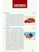
1. Introduction ...115
1. Definition. 2. Classifications of Machine Design.
3. General Considerations in Machine Design.
4. General Procedure in Machine Design.
5. Fundamental Units. 6. Derived Units. 7. System of
Units. 8. S.I Units (International System of Units).
9. Metre. 10. Kilogram. 11. Second. 12. Presentation
of Units and their values. 13. Rules for S.I. Units.
14. Mass and Weight. 15. Inertia. 16. Laws of Motion.
17. Force. 18. Absolute and Gravitational Units of
Force. 19. Moment of a Force. 20. Couple. 21. Mass
Density. 22. Mass Moment of Inertia. 23. Angular
Momentum. 24. Torque. 25. Work. 26. Power.
27. Energy.
2. Engineering Materials and Their Properties ...1652
1. Introduction. 2. Classification of Engineering
Materials. 3. Selection of Materials for Engineering
Purposes. 4. Physical Properties of Metals.
5. Mechanical Properties of Metals. 6. Ferrous Metals.
7. Cast Iron. 8. Types of Cast Iron. 9. Alloy Cast Iron.
10. Effect of Impurities on Cast Iron. 11. Wrought Iron.
12. Steel. 13. Steels Designated on the Basis of
Mechanical Properties. 14. Steels Designated on the
Basis of Chemical Composition. 15. Effect of Impurities
on Steel. 16. Free Cutting Steels. 17. Alloy Steels.
18. Indian Standard Designation of Low and Medium
Alloy Steels. 19. Stainless Steel. 20. Heat Resisting
Steels. 21. Indian Standard Designation of High Alloy
Steels (Stainless Steel and Heat Resisting Steel).
22. High Speed Tool Steels. 23. Indian Standard
Designation of High Speed Tool Steel. 24. Spring Steels.
25. Heat Treatment of Steels. 26. Non-ferrous Metals.
27. Aluminium. 28. Aluminium Alloys. 29. Copper.
30. Copper Alloys. 31. Gun Metal. 32. Lead. 33. Tin.
34. Bearing Metals. 35. Zinc Base Alloys. 36. Nickel
Base Alloys. 37. Non-metallic Materials.
CONTENTS
(viii)
3. Manufacturing Considerations in Machine Design ...5386
1. Introduction. 2. Manufacturing Processes.
3. Casting. 4. Casting Design. 5. Forging. 6. Forging
Design. 7. Mechanical Working of Metals. 8. Hot
Working. 9. Hot Working Processes. 10. Cold Working.
11. Cold Working Processes. 12. Interchangeability.
13. Important Terms Used in Limit System. 14. Fits.
15. Types of Fits. 16. Basis of Limit System. 17. Indian
Standard System of Limits and Fits. 18. Calculation of
Fundamental Deviation for Shafts. 19. Calculation of
Fundamental Deviation for Holes. 20. Surface
Roughness and its Measurement. 21. Preferred
Numbers.
4. Simple Stresses in Machine Parts ...87119
1. Introduction. 2. Load. 3. Stress. 4. Strain. 5. Tensile
Stress and Strain. 6. Compressive Stress and Strain.
7. Young's Modulus or Modulus of Elasticity. 8. Shear
Stress and Strain 9. Shear Modulus or Modulus of
Rigidity. 10. Bearing Stress. 11. Stress-strain Diagram.
12. Working Stress. 13. Factor of Safety. 14. Selection
of Factor of Safety. 15. Stresses in Composite Bars.
16. Stresses Due to Change in TemperatureThermal
Stresses. 17. Linear and Lateral Strain. 18. Poisson's
Ratio. 19. Volumetric Strain. 20. Bulk Modulus.
21. Relation Between Bulk Modulus and Young's
Modulus. 22. Relation Between Young's Modulus and
Modulus of Rigidity. 23. Impact Stress. 24. Resilience.
5. Torsional and Bending Stresses in Machine Parts ...120180
1. Introduction. 2. Torsional Shear Stress. 3. Shafts in
Series and Parallel. 4. Bending Stress in Straight Beams.
5. Bending Stress in Curved Beams. 6. Principal Stresses
and Principal Planes. 7. Determination of Principal
Stresses for a Member Subjected to Bi-axial Stress.
8. Application of Principal Stresses in Designing
Machine Members. 9. Theories of Failure Under Static
Load. 10. Maximum Principal or Normal Stress Theory
(Rankines Theory). 11. Maximum Shear Stress Theory
(Guests or Trescas Theory). 12. Maximum Principal
Strain Theory (Saint Venants Theory). 13. Maximum
Strain Energy Theory (Haighs Theory). 14. Maximum
Distortion Energy Theory (Hencky and Von Mises
Theory). 15. Eccentric LoadingDirect and Bending
Stresses Combined. 16. Shear Stresses in Beams.
(ix)
6. Variable Stresses in Machine Parts ...181223
1. Introduction. 2. Completely Reversed or Cyclic
Stresses. 3. Fatigue and Endurance Limit. 4. Effect of
Loading on Endurance LimitLoad Factor. 5. Effect of
Surface Finish on Endurance LimitSurface Finish
Factor. 6. Effect of Size on Endurance LimitSize
Factor. 7. Effect of Miscellaneous Factors on Endurance
Limit. 8. Relation Between Endurance Limit and
Ultimate Tensile Strength. 9. Factor of Safety for Fatigue
Loading. 10. Stress Concentration. 11. Theoretical or
Form Stress Concentration Factor. 12. Stress
Concentration due to Holes and Notches. 13. Methods
of Reducing Stress Concentration. 14. Factors to be
Considered while Designing Machine Parts to Avoid
Fatigue Failure. 15. Stress Concentration Factor for
Various Machine Members. 16. Fatigue Stress
Concentration Factor. 17. Notch Sensitivity.
18. Combined Steady and Variable Stresses. 19. Gerber
Method for Combination of Stresses. 20. Goodman
Method for Combination of Stresses. 21. Soderberg
Method for Combination of Stresses. 22. Combined
Variable Normal Stress and Variable Shear Stress.
23. Application of Soderberg's Equation.
7. Pressure Vessels ...224260
1. Introduction. 2. Classification of Pressure Vessels.
3. Stresses in a Thin Cylindrical Shell due to an Internal
Pressure. 4. Circumferential or Hoop Stress.
5. Longitudinal Stress. 6. Change in Dimensions of a
Thin Cylindrical Shell due to an Internal Pressure.
7. Thin Spherical Shells Subjected to an Internal
Pressure. 8. Change in Dimensions of a Thin Spherical
Shell due to an Internal Pressure. 9. Thick Cylindrical
Shell Subjected to an Internal Pressure. 10. Compound
Cylindrical Shells. 11. Stresses in Compound
Cylindrical Shells. 12. Cylinder Heads and Cover
Plates.
8. Pipes and Pipe Joints ...261280
1. Introduction. 2. Stresses in Pipes. 3. Design of Pipes.
4. Pipe Joints. 5. Standard Pipe Flanges for Steam.
6. Hydraulic Pipe Joint for High Pressures. 7. Design
of Circular Flanged Pipe Joint. 8. Design of Oval
Flanged Pipe Joint. 9. Design of Square Flanged Pipe
Joint.
(x)
9. Riveted Joints ...281340
1. Introduction. 2. Methods of Riveting. 3. Material of
Rivets. 4. Essential Qualities of a Rivet. 5. Manufacture
of Rivets. 6. Types of Rivet Heads. 7. Types of Riveted
Joints. 8. Lap Joint. 9. Butt Joint. 10. Important Terms
Used in Riveted Joints. 11. Caulking and Fullering.
12. Failures of a Riveted Joint. 13. Strength of a Riveted
Joint. 14. Efficiency of a Riveted Joint. 15. Design of
Boiler Joints. 16. Assumptions in Designing Boiler
Joints. 17. Design of Longitudinal Butt Joint for a Boiler.
18. Design of Circumferential Lap Joint for a Boiler.
19. Recommended Joints for Pressure Vessels.
20. Riveted Joint for Structural Use Joints of Uniform
Strength (Lozenge Joint). 21. Eccentric Loaded Riveted
Joint.
10. Welded Joints ...341376
1. Introduction. 2. Advantages and Disadvantages of
Welded Joints over Riveted Joints. 3. Welding
Processes. 4. Fusion Welding. 5. Thermit Welding.
6. Gas Welding. 7. Electric Arc Welding. 8. Forge
Welding. 9. Types of Welded Joints. 10. Lap Joint.
11. Butt Joint. 12. Basic Weld Symbols.
13. Supplementary Weld Symbols. 14. Elements of a
Weld Symbol. 15. Standard Location of Elements of a
Welding Symbol. 16. Strength of Transverse Fillet
Welded Joints. 17. Strength of Parallel Fillet Welded
Joints. 18. Special Cases of Fillet Welded Joints.
19. Strength of Butt Joints. 20. Stresses for Welded
Joints. 21. Stress Concentration Factor for Welded
Joints. 22. Axially Loaded Unsymmetrical Welded
Sections. 23. Eccentrically Loaded Welded Joints.
24. Polar Moment of Inertia and Section Modulus of
Welds.
11. Screwed Joints ...377430
1. Introduction. 2. Advantages and Disadvantages of
Screwed Joints. 3. Important Terms used in Screw
Threads. 4. Forms of Screw Threads. 5. Location of
Screwed Joints. 6. Common Types of Screw Fastenings.
7. Locking Devices. 8. Designation of Screw Threads.
9. Standard Dimensions of Screw Threads. 10. Stresses
in Screwed Fastening due to Static Loading. 11. Initial
Stresses due to Screwing Up Forces. 12. Stresses due
to External Forces. 13. Stress due to Combined Forces.
14. Design of Cylinder Covers. 15. Boiler Stays.
16. Bolts of Uniform Strength. 17. Design of a Nut.
(xi)
18. Bolted Joints under Eccentric Loading. 19. Eccentric
Load Acting Parallel to the Axis of Bolts. 20. Eccentric
Load Acting Perpendicular to the Axis of Bolts.
21. Eccentric Load on a Bracket with Circular Base.
22. Eccentric Load Acting in the Plane Containing the
Bolts.
12. Cotter and Knuckle Joints ...431469
1. Introduction. 2. Types of Cotter Joints. 3. Socket
and Spigot Cotter Joint. 4. Design of Socket and Spigot
Cotter Joint. 5. Sleeve and Cotter Joint. 6. Design of
Sleeve and Cotter Joint. 7. Gib and Cotter Joint.
8. Design of Gib and Cotter Joint for Strap End of a
Connecting Rod. 9. Design of Gib and Cotter Joint for
Square Rods. 10. Design of Cotter Joint to Connect
Piston Rod and Crosshead. 11. Design of Cotter
Foundation Bolt. 12. Knuckle Joint.13. Dimensions of
Various Parts of the Knuckle Joint.14. Methods of
Failure of Knuckle Joint. 15. Design Procedure of
Knuckle Joint. 16. Adjustable Screwed Joint for Round
Rods (Turn Buckle). 17. Design of Turn Buckle.
13. Keys and Coupling ...470508
1. Introduction. 2. Types of Keys. 3. Sunk Keys.
4. Saddle Keys. 5. Tangent Keys. 6. Round Keys.
7. Splines. 8. Forces acting on a Sunk Key. 9. Strength
of a Sunk Key. 10. Effect of Keyways. 11. Shaft
Couplings. 12. Requirements of a Good Shaft Coupling.
13. Types of Shaft Couplings. 14. Sleeve or Muff
Coupling. 15. Clamp or Compression Coupling.
16. Flange Coupling. 17. Design of Flange Coupling.
18. Flexible Coupling. 19. Bushed Pin Flexible
Coupling. 20. Oldham Coupling. 21. Universal
Coupling.
14. Shafts ...509557
1. Introduction. 2. Material Used for Shafts.
3. Manufacturing of Shafts. 4. Types of Shafts.
5. Standard Sizes of Transmission Shafts. 6. Stresses in
Shafts. 7. Maximum Permissible Working Stresses for
Transmission Shafts. 8. Design of Shafts. 9. Shafts
Subjected to Twisting Moment Only. 10. Shafts
Subjected to Bending Moment Only. 11. Shafts
Subjected to Combined Twisting Moment and Bending
Moment. 12. Shafts Subjected to Fluctuating Loads.
13. Shafts Subjected to Axial Load in addition to
Combined Torsion and Bending Loads. 14. Design of
Shafts on the Basis of Rigidity.

