LÝ THUYẾT DIODE (MẠCH điện tử SLIDE)
Bạn đang xem bản rút gọn của tài liệu. Xem và tải ngay bản đầy đủ của tài liệu tại đây (1.26 MB, 36 trang )
anode
bulk resistance = điện trở khối
cathode
diode
ideal diode = diode lý tưởng
knee voltage = điện áp gối
linear device = dụng cụ tuyến tính
load line = đường tải
maximum forward current = dòng
thuận cực đại
nonlinear device = dụng cụ phi tuyến
Ohmic resistance = điện trở Ohm
power rating = định mức cơng suất
up-down analysis = phân tích tăng-giảm
3-1 Các ý tưởng cơ bản
3-2 Diode lý tưởng
3-3 Xấp xỉ bậc 2
3-4 Xấp xỉ bậc 3
3-5 Trounleshooting
3-6 Phân tích mạch tăng-giảm
3-7 Đọc bảng dữ liệu
3-8 Cách tính điện trở khối
3-9 Điện trở DC của diode
3-10 Đường tải
3-11 Diode dán bề mặt
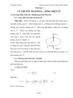
Properties of Diodes
Figure 1.10 – The Diode Transconductance Curve 2
ID
(mA)
• VD = Bias Voltage
• ID = Current through
Diode. ID is Negative
for Reverse Bias and
Positive for Forward
Bias
IS
VBR
~V
VD
• IS = Saturation
Current
• VBR = Breakdown
Voltage
• V = Barrier Potential
Voltage
(nA)
Kristin Ackerson, Virginia Tech EE
Spring 2002
Properties of Diodes
The Shockley Equation
• The transconductance curve on the previous slide is characterized by
the following equation:
ID = IS(eVD/ VT – 1)
• As described in the last slide, ID is the current through the diode, IS is
the saturation current and VD is the applied biasing voltage.
• VT is the thermal equivalent voltage and is approximately 26 mV at room
temperature. The equation to find VT at various temperatures is:
k = 1.38 x 10⁻²³ J/K
VT = kT
q
T = temperature in Kelvin
q = 1.6 x 10 -19 C
is the emission coefficient for the diode. It is determined by the way
the diode is constructed. It somewhat varies with diode current. For a
silicon diode is around 2 for low currents and goes down to about 1
at higher currents
Kristin Ackerson, Virginia Tech EE
Spring 2002
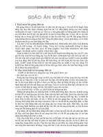
Diode Circuit Models
The Ideal Diode
Model
The diode is designed to allow current to flow in
only one direction. The perfect diode would be a
perfect conductor in one direction (forward bias)
and a perfect insulator in the other direction
(reverse bias). In many situations, using the ideal
diode approximation is acceptable.
Example: Assume the diode in the circuit below is ideal. Determine the
value of ID if a) VA = 5 volts (forward bias) and b) VA = -5 volts (reverse
bias)
a) With VA > 0 the diode is in forward bias
and is acting like a perfect conductor so:
RS = 50
ID
VA
+
_
ID = VA/RS = 5 V / 50 = 100 mA
b) With VA < 0 the diode is in reverse bias
and is acting like a perfect insulator,
therefore no current can flow and ID = 0.
Kristin Ackerson, Virginia Tech EE
Spring 2002
Diode Circuit Models
The Ideal Diode with
Barrier Potential
This model is more accurate than the simple
ideal diode model because it includes the
approximate barrier potential voltage.
Remember the barrier potential voltage is the
+
V
voltage at which appreciable current starts to
flow.
Example: To be more accurate than just using the ideal diode model
include the barrier potential. Assume V = 0.3 volts (typical for a
germanium diode) Determine the value of ID if VA = 5 volts (forward bias).
RS = 50
ID
VA
+
_
With VA > 0 the diode is in forward bias
and is acting like a perfect conductor
so write a KVL equation to find ID:
0 = VA – IDRS - V
V
+
ID = VA - V = 4.7 V = 94 mA
RS
50
Kristin Ackerson, Virginia Tech EE
Spring 2002
Diode Circuit Models
The Ideal Diode
with Barrier
Potential and
Linear Forward
Resistance
+
V
RF
RF = VD
This model is the most accurate of the three. It includes a
linear forward resistance that is calculated from the slope of
the linear portion of the transconductance curve. However,
this is usually not necessary since the RF (forward
resistance) value is pretty constant. For low-power
germanium and silicon diodes the RF value is usually in the
2 to 5 ohms range, while higher power diodes have a RF
value closer to 1 ohm.
ID
Linear Portion of
transconductance
curve
ID
ID
VD
VD
Kristin Ackerson, Virginia Tech EE
Spring 2002
Diode Circuit Models
The Ideal Diode
with Barrier
Potential and
Linear Forward
Resistance
Example: Assume the diode is a low-power diode
with a forward resistance value of 5 ohms. The
barrier potential voltage is still: V = 0.3 volts
(typical for a germanium diode) Determine the value
of ID if VA = 5 volts.
RS = 50
Once again, write a KVL equation
for the circuit:
ID
VA
+
_
V
0 = VA – IDRS - V - IDRF
+
ID = VA - V = 5 – 0.3 = 85.5 mA
RS + RF
50 + 5
RF
Kristin Ackerson, Virginia Tech EE
Spring 2002
Diode Circuit Models
Values of ID for the Three Different Diode Circuit Models
ID
Ideal Diode
Model
Ideal Diode
Model with
Barrier
Potential
Voltage
Ideal Diode
Model with
Barrier
Potential and
Linear Forward
Resistance
100 mA
94 mA
85.5 mA
These are the values found in the examples on previous
slides where the applied voltage was 5 volts, the barrier
potential was 0.3 volts and the linear forward resistance
value was assumed to be 5 ohms.
Kristin Ackerson, Virginia Tech EE
Spring 2002
Forward Bias Region
Reverse Bias Region
Reverse
breakdown
ID = Is (e
VD
ηVT
-1)
An ideal diode is a two-terminal device
defined by the following non-linear
(currentvoltage) iv-characteristic:
Rs is inevitable series resistance of a
real device structure. Current
controlled current source represents
ideal exponential behavior of diode.
Capacitor specification includes
depletion-layer capacitance for
reverse-bias region as well as
diffusion capacitance associated with
junction under forward bias.
Typical default values: Saturation
current = 10 fA, Rs = 0, Transit
time = 0 seconds
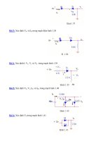
Loop equation for given circuit is:
V I D R VD
V and R may represent Thévenin
equivalent of a more complex 2terminal network.Objective of
diode circuit analysis is to find
quiescent operating point for
diode, consisting of dc current and
voltage that define diode’s i-v
characteristic.
This is also called the load line for
the diode. Solution to this equation
can be found by:
• Graphical analysis using load-line
method.
• Analysis with diode’s
mathematical model.
• Simplified analysis with ideal
diode model.
• Simplified analysis using constant
voltage drop model.
Problem: Find Q-point
Given data: V=10 V, R=10k.
Analysis: 10 I D 104 VD
To define the load line we use,
VD= 0 I D (10V / 10k) 1mA
VD= 5 V, ID =0.5 mA
These points and the resulting
load line are plotted.Q-point is
given by intersection of load line
and diode characteristic:
Q-point = (0.95 mA, 0.6 V)