Tài liệu IP Multicast Distribution Trees and Control Protocols docx
Bạn đang xem bản rút gọn của tài liệu. Xem và tải ngay bản đầy đủ của tài liệu tại đây (342.12 KB, 116 trang )
2
IP Multicast Distribution
Trees and Control
Protocols
Overview
This lesson represents an entry point to IP multicast services, presents the
functional model of IP multicasting and gives an overview of technologies present
in IP multicasting. The student will grasp the idea of IP multicasting, its benefits
and associated caveats, determine various types of multicast applications, and gain
an understanding of the IP multicast conceptual model and its implementation
prerequisites.
Objectives
Upon completion of this chapter, the student will be able to:
n List the functions performed with a multicast-enabled network
n Identify the types of multicast distribution trees and the way they are built
n Explain various multicast routing protocols and their place in different network
/ application environments
n Identify the protocols for group membership reporting
2-2 IP Multicast Technology Copyright 2000, Cisco Systems, Inc.
Functions of Multicast Enabled Networks
Objectives
Upon completion of this section, the student will be able to:
n Identify the functions of multicast-enabled routers
n Explain how multicast data is forwarded loop free to receiver segments
n Determine methods for scoping multicast streams
Copyright 2000, Cisco Systems, Inc. IP Multicast Distribution Trees and Control Protocols 2-3
© 2000, Cisco Systems, Inc. www.cisco.com IP Multicast Primer Chapter2 Page5
Multicast Forwarding
Multicast Forwarding
•Multicast Routing works the opposite
way of Unicast Routing
• Unicast Routing is concerned with where
the packet is going
• Multicast Routing is concerned with where
the packet comes from
•Multicast Routing uses “Reverse Path
Forwarding” to prevent forwarding loops
In unicast routing, when the router receives the packet, the decision about where to
forward the packet is made depending on the packet’s destination address. In
multicast routing the decision about where to forward the multicast packet depends
on where the packet came from.
Multicast routers must know the packet’s origin, rather than its destination, which
is just the opposite in unicast routing. In multicast origination, the IP address
denotes the known source and the destination IP address denotes a group of
unknown receivers.
Multicast routing uses mechanism called Reverse Path Forwarding (RPF) to
prevent forwarding loops and to ensure the shortest path from the source to the
receivers.
2-4 IP Multicast Technology Copyright 2000, Cisco Systems, Inc.
© 2000, Cisco Systems, Inc. www.cisco.com IP Multicast Primer Chapter2 Page6
Reverse Path Forwarding (RPF)
Reverse Path Forwarding (RPF)
• What is RPF?
• A router forwards a multicast datagram only if
received on the upstream interface to the source
(I.e. it follows the distribution tree)
• The RPF Check
• The routing table for unicast is checked against the
“source” address in the multicast datagram
• If the datagram arrived on the interface specified in
the routing table for the source address:
– The RPF check succeeds
– Otherwise, the RPF Check fails
When a router receives a multicast packet, it checks its routing tables (usually
unicast) to see if the interface the packet came from provides the shortest path
back to the source. If the interface provides the shortest path to the source, the
router will forward the packet. Otherwise, if the multicast packet is received from
some other interface that does not provide the shortest path to the source, it’s
silently discarded.
This mechanism that multicast routing utilizes is called Reverse Path Forwarding
(RPF). RPF ensures that multicast packets will follow the shortest path from the
source to the receivers and that there will be no loops on that path.
Copyright 2000, Cisco Systems, Inc. IP Multicast Distribution Trees and Control Protocols 2-5
© 2000, Cisco Systems, Inc. www.cisco.com IP Multicast Primer Chapter2 Page7
Reverse Path Forwarding (cont.)
Reverse Path Forwarding (cont.)
•Reverse Path Forwarding (RPF) Check:
• If the RPF check succeeds, the datagram
is forwarded
• If the RPF check fails, the datagram
is typically silently discarded
• When a datagram is forwarded, it is sent out
of each interface in the outgoing interface
list
• The packet is never sent back out of the
RPF interface!
After the router receives a multicast packet, it performs an RPF check. If the RPF
check succeeds, the packet is forwarded; otherwise, it’s silently discarded.
The multicast packet is forwarded out of each interface that is in the Outgoing
Interface List (OIL). OIL entries point to the current router’s downstream
multicast neighbors.
The incoming interface (or RPF interface) on which the packet was received is
never in the OIL; therefore, the packet is never forwarded back out of the RPF
interface.
2-6 IP Multicast Technology Copyright 2000, Cisco Systems, Inc.
Routers perform an RPF check to insure that arriving multicast packets were
received via the interface that is on the most direct path to the source that sent the
packets.
In the above example, each router forwards received multicast packets to each of
its neighbor routers. (This is indicated by the arrows that indicate the initial
multicast traffic flow from source 151.10.3.21 throughout the network.) Observe
that the two routers in the middle of the picture are each receiving multicast
packets via the most direct path from the source indicated by the green arrows.
These received packets arrived via the RPF interface (indicated by the green
arrows) so both routers forward the multicast packets to all neighbors; in this case,
each other. This results in the two routers receiving packets via the non-RPF
interface (i.e. an interface that is not on the shortest path to the source) as shown
by the red arrows. This causes the RPF check to fail and the packets to be silently
discarded.
Copyright 2000, Cisco Systems, Inc. IP Multicast Distribution Trees and Control Protocols 2-7
Let’s take a closer look at a failed RPF check.
The router in our slide receives a multicast packet from source 151.10.3.21 on
interface S0. The router performs the RPF check by looking into the unicast
routing table. The unicast routing table indicates that interface S1 is the shortest
path to the network 151.10.0.0/16. Because interface S0 is not the shortest path to
the network from which the packet from the source 151.10.3.21 came from, the
RPF check fails and the packet is discarded.
2-8 IP Multicast Technology Copyright 2000, Cisco Systems, Inc.
Now let’s take a closer look at a successful RPF check.
The router in our slide receives a multicast packet from source 151.10.3.21 on
interface S1. The router performs the RPF check by looking into the unicast
routing table. The unicast routing table indicates that interface S1 is the shortest
path to the network 151.10.0.0/16. Since interface S1 is the shortest path to the
network from which the packet from the source 151.10.3.21 came from, the RPF
check succeeds and the packet is forwarded on every interface in OIL. In our
example, OIL for current multicast packet consists of interfaces S2 and E0, so the
packet is forwarded on interfaces S2 and E0.
Copyright 2000, Cisco Systems, Inc. IP Multicast Distribution Trees and Control Protocols 2-9
An RPF check is always done with respect to the incoming interface – the RPF
interface. The RPF check will succeed if the incoming interface is the shortest
path to the source.
The RPF interface is determined either by the underlying unicast routing protocol
or the dedicated multicast routing protocol (e.g. DVMRP, MBGP, etc.).
Note that changes in the unicast topology will not necessarily immediately reflect a
change in RPF if the multicast routing protocol relies on underlying unicast routing
tables. It depends on how frequently the RPF check is performed on a multicast
forwarding entry - every five seconds is the current Cisco default.
2-10 IP Multicast Technology Copyright 2000, Cisco Systems, Inc.
Sometimes we want to define the boundaries for certain multicast traffic. We don’t
want all our multicast traffic to be heard all over our network or outside of our
network boundaries, and, also, we may not want some external multicast traffic to
enter our network. In order to achieve this goal we can use TTL Thresholds.
TTL Thresholds may be set on a multicast router interface to limit the forwarding
of multicast traffic to outgoing packets with TTLs greater than the TTL Threshold.
A Zero TTL Threshold implies that no threshold has been set.
As a multicast packet arrives, TTL is decremented by one. If the resulting TTL is
less or equal to 0, it’s dropped. If a multicast packet is to be forwarded out of an
interface with a non-zero TTL Threshold, then its TTL is checked against the TTL
Threshold. If a packet’s TTL is less than the specified threshold, it is not
forwarded out of the interface.
Copyright 2000, Cisco Systems, Inc. IP Multicast Distribution Trees and Control Protocols 2-11
The slide above shows an example of multicast scoping using TTL Thresholds.
Interface S1 has a TTL Threshold set to 16, interface S2 has a TTL Threshold set
to 64, and interface E0 has a TTL threshold set to 0, which means that the latter
interface doesn’t have any TTL Threshold set.
The router receives a multicast packet with TTL 24 on an interface S0. The TTL
is first decremented by the normal router IP packet processing to 23. Before
sending the packet on all interfaces in the OIL, the router checks for TTL
Thresholds set on those interfaces.
Note In the example we assume that RPF-check succeeded on the interface S0.
Since the TTL Threshold on interfaces S1 (TTL Threshold=16) and E0 (TTL
Threshold=0) is less than TTL of the multicast packet, the packet is forwarded.
Interface S2 has the TTL Threshold set to 64, which is greater than TTL of the
multicast packet, so the packet is not forwarded over interface S2.
2-12 IP Multicast Technology Copyright 2000, Cisco Systems, Inc.
In the example above, the Engineering or Marketing departments can prevent
department- related multicast traffic from leaving their network by using a TTL of
16 for their multicast sessions – hence their sources have to send all the multicast
traffic with a TTL less than or equal to 16.
Similarly, Company ABC can prevent private multicast traffic from leaving their
network by using a TTL of 128 for their multicast sessions.
Copyright 2000, Cisco Systems, Inc. IP Multicast Distribution Trees and Control Protocols 2-13
Although TTL Scoping looks easy to implement, there are many problems with it.
If we use TTL Scoping with broadcast and prune multicast protocols, the router,
which discards the packet, will not be able to prune any upstream source. It is also
impossible to configure overlapping zones with TTL Scoping.
Address Scoping allows the multicast boundaries to be established per group
address and is much more flexible than TTL Scoping. The multicast traffic that
does not match the address within a scope is dropped on an incoming interface as
well as on an outgoing interface.
If we use Address Scoping for overlapping zones, we must use separate address
spaces within these zones, which makes the administration of multicast addresses
difficult.
2-14 IP Multicast Technology Copyright 2000, Cisco Systems, Inc.
In the example above, the company uses private multicast address range
239.128.0.0/10 and does Address Scoping on its boundaries. Departments within
the company use the subset of that range. Eng and Mkt departments use the
subset ranges 239.129.0.0/16 and 239.130.0.0/16 respectively.
Copyright 2000, Cisco Systems, Inc. IP Multicast Distribution Trees and Control Protocols 2-15
Summary
After completing this section, the student should be able to:
n Identify the functions of multicast enabled routers
n Explain how multicast data is forwarded loop free to receiver segments
n Identify methods for scoping multicast streams
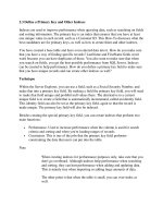
Review Questions
n What is the first action of a router upon receiving a multicast datagram?
n What is an RPF Interface and how is it identified?
n How can you constrain multicast streams to be propagated outside a certain
scope?
2-16 IP Multicast Technology Copyright 2000, Cisco Systems, Inc.
Multicast Distribution Trees and Protocol Types
Objectives
Upon completion of this section, the student will be able to:
n Distinguish between source-rooted and shared distribution trees
n Identify the meaning of “push” and “pull” models and their association with
dense and sparse mode multicast protocols
Copyright 2000, Cisco Systems, Inc. IP Multicast Distribution Trees and Control Protocols 2-17
Multicast Distribution Trees define the path from the source to receivers over
which the multicast traffic flows.
There are two types of Multicast Distribution Trees— Source-rooted or Shortest
Path Trees and Shared Trees.
In the case of a Source rooted tree, a separate tree is built for each source to all
members of its group. Because the Source rooted tree takes a direct, or shortest,
path from source to its receivers, it is also called Shortest Path Tree (SPT).
Shared tree protocols create multicast forwarding paths that rely on a central
“core” router that serves as a rendezvous point between multicast sources and
destinations. Sources initially send their multicast packets to the rendezvous point,
which, in turn, forwards data via a shared tree to the members of the group. A
shared tree is less efficient than a SPT (paths between the source and receivers
are not necessary the shortest), but it is less demanding on routers (memory,
CPU).
There are basically two types of multicast routing protocols. Dense mode protocols
flood multicast traffic to all parts of the network and prune back the flows where
there are no receivers using a periodic flood and prune mechanism. Sparse mode
protocols use an explicit join mechanism where distribution trees are built on
demand by explicit tree join messages sent by routers that have directly connected
receivers.
2-18 IP Multicast Technology Copyright 2000, Cisco Systems, Inc.
The example above shows a Shortest Path Tree (SPT) between a source Source1
and receivers Receivers1 and Receiver2. We assume that the path between
source and receivers over routers A, C and E is the path with the lowest cost.
Packets are forwarded according to Source and Group Address pair down the
SPT. For this reason, we refer to the forwarding state associated with the SPT by
the notation (S, G) (pronounced “S comma G”) where S is the IP address of the
source and G is the multicast group address.
Copyright 2000, Cisco Systems, Inc. IP Multicast Distribution Trees and Control Protocols 2-19
Here is another example of SPT where source Source2 is active and is sending
multicast packets to receivers Receiver1 and Receiver2. We can see that a
separate SPT is built for this purpose, this time with source Source2 at the root of
the SPT. The key point here is that a separate SPT is built for every source “S”
sending to group “G”.
2-20 IP Multicast Technology Copyright 2000, Cisco Systems, Inc.
The example above shows a Shared Distribution Tree. Router D is the root of this
Shared Tree, which is built from router D to routers C and E towards receivers
Receiver1 and Receiver2. In PIM, the root of the Shared Tree is called a
Rendezvous Point.
Packets are forwarded down the Shared Distribution Tree to the receivers. The
default forwarding state for the Shared Tree is identified by the notation (*, G)
(pronounced “star comma G”) where * is a wildcard entry, meaning any source,
and G is the multicast group address.
Copyright 2000, Cisco Systems, Inc. IP Multicast Distribution Trees and Control Protocols 2-21
In this example of a Shared Distribution Tree, we can see that sources Source1
and Source2 are sending multicast packets towards a Rendezvous Point via Source
Path Trees, and, from the Rendezvous Point, the multicast packets are flowing via
a Shared Distribution Tree towards receivers Receiver1 and Receiver2.
2-22 IP Multicast Technology Copyright 2000, Cisco Systems, Inc.
The multicast forwarding entries that appear in multicast forwarding tables can be
read in the following way: (S, G) – for the source S sending to the group G; those
entries typically reflect the shortest path tree but may also appear on a shared tree.
(*, G) – for any source (*) sending to the group G; those entries reflect the shared
tree, but are also created (in Cisco routers) for any existing (S, G) entry.
Copyright 2000, Cisco Systems, Inc. IP Multicast Distribution Trees and Control Protocols 2-23
Shortest Path Tree state entries use more router memory because there is an entry
for each sender and group pair, but the traffic is sent over the optimal path to each
receiver ,thus minimizing the delay in packet delivery.
Shared Distribution Tree state entries consume less router memory, but we might
get sub-optimal paths from a source to receivers, thus introducing extra delay in
packet delivery.
2-24 IP Multicast Technology Copyright 2000, Cisco Systems, Inc.
Dense Mode protocols implement the “PUSH” model for multicast data delivery.
This model is also called broadcast and prune or flood and prune because initial
traffic is flooded to all points in the network. After the initial flood, branches
without receivers are pruned. After a timeout, traffic is flooded throughout the
network again.
Copyright 2000, Cisco Systems, Inc. IP Multicast Distribution Trees and Control Protocols 2-25
Sparse Mode protocols use the “PULL” model for multicast data delivery. The
model can also be described as an explicit join model because last hop routers pull
the traffic from a rendezvous point or from the source. This way branches without
receivers never get the multicast traffic.