Tài liệu Essential Silverlight 3- P3 ppt
Bạn đang xem bản rút gọn của tài liệu. Xem và tải ngay bản đầy đủ của tài liệu tại đây (721.34 KB, 50 trang )
ptg
Chapter 3: Graphics
68
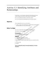
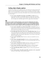
One other feature of linear and radial gradients is the capability to
specify the behavior when the display position maps to some position
outside the range of the gradient line. The
SpreadMethod
property defines
that behavior. The
Pad
mode repeats the closest point when off the line, the
Reflect
mode mirrors to a point on the line, and the
Repeat
mode simply
takes the position modulo the length of the line as shown in Figure 3.21.
Figure 3.21: SpreadMethod example
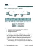
Figure 3.22: ImageBrush example
Pad Repeat Reflect
Image Brushes
The role of the image brush is to map a screen position to a pixel in the
specified image. For example, the following XAML would result in the
image brush rendering shown in Figure 3.22.
<Canvas xmlns=" /><Ellipse
From the Library of Lee Bogdanoff
Please purchase PDF Split-Merge on www.verypdf.com to remove this watermark.
ptg
Width="450"
Height="450"
Stroke="Black"
StrokeThickness="10"
>
<Ellipse.Fill>
<ImageBrush ImageSource="silverlight.png"/>
</Ellipse.Fill>
</Ellipse>
</Canvas>
Strokes
The previous section showed how to use a brush to color the fill of a shape.
You can also use a brush to add color to the outline of a shape by setting
the stroke properties. For example, the following XAML generates the
output shown in Figure 3.23.
Graphics Elements 69
Figure 3.23: Sample stroke applied to an ellipse
<Canvas xmlns=" /><Ellipse
Stroke="Black"
StrokeThickness="10"
Canvas.Left="50"
Canvas.Top="50"
Width="400"
Height="400"
/>
</Canvas>
From the Library of Lee Bogdanoff
Please purchase PDF Split-Merge on www.verypdf.com to remove this watermark.
ptg
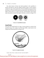
Stroke
A stroke transforms geometry to a widened form that describes the shape
outline instead of the shape fill. Silverlight fills the widened geometry
with exactly the same rendering rules as the main shape fill. For example,
Figure 3.24 shows an example of a widened ellipse.
The widening process expands the original geometry by half the stroke
thickness to form an outer outline. The widening process also shrinks the
original geometry by half the stroke thickness to form an inner outline.
The outer and inner outlines combine to form two figures Silverlight fills
to produce the resulting stroke.
Chapter 3: Graphics
70
Outter Outline
Inner Outline
Figure 3.24: The widening process applied
to an ellipse
Technical Insight
One side effect of the widening process is that local self-intersection can
occur. For example, the process of widening a triangle generates several
self-intersections as shown in Figure 3.25. One option is to run a loop
removal algorithm to remove these intersections before rasterization.
However, by simply filling the new geometry with the
NonZero
fill rule,
these self intersections are not visible to the end user.
From the Library of Lee Bogdanoff
Please purchase PDF Split-Merge on www.verypdf.com to remove this watermark.
ptg
Dashes
To add dashes to your strokes, specify an array of distances alternating between
the dash filled distance and the gap distance. For example, the simple dash
array in the following XAML generates the output shown in Figure 3.26.
Graphics Elements 71
Figure 3.25: The widening process applied to a triangle
Figure 3.26: StrokeDashArray example of long
and short dashes
From the Library of Lee Bogdanoff
Please purchase PDF Split-Merge on www.verypdf.com to remove this watermark.
ptg
<Canvas xmlns=" /><Ellipse
Stroke="Black"
StrokeThickness="10"
StrokeDashA rray="5, 4, 2, 4"
Canvas.Left="50"
Canvas.Top="50"
Width="400"
Height="400"
/>
</Canvas>
Chapter 3: Graphics
72
Technical Insight
Dashes are also a geometry modifier built on top of the stroke geometry
modifier. When you specify a
StrokeDashA rray
, Silverlight takes the
output of the pen and subdivides it into smaller geometries. Large num-
bers of dashes can result in significant slowdowns in rendering speed and
therefore you should use them sparingly.
Canvas
Every example shown so far has had a single root
Canvas
element with a set
of
Shape
elements contained within it. In addition to providing a conven-
ient container, the
Canvas
element also enables you to modify the rendering
primitives it contains as a group. In particular, the
Canvas
element enables
the following:
• Naming groups of elements
• Grouping shapes so that you can add or remove the group with a
single operation
• Applying a transform to the group of elements
• Clipping a group of elements
• Apply an opacity or opacity mask effect to a group of elements
Transforms, clipping, and opacity effects are available on both individ-
ual shapes and the
Canvas
element.
From the Library of Lee Bogdanoff
Please purchase PDF Split-Merge on www.verypdf.com to remove this watermark.
ptg
Transforms
A transform enables you to position, rotate, scale, or skew a shape or
group of shapes. To transform a group of primitives, you can set the
RenderTransform
on the
Canvas
element as exemplified in the following
listing to achieve the result shown in Figure 3.27.
Graphics Elements 73
PERFORMANCE TIP
For individual shapes, it is faster to express clipping or opacity as a
different geometry or a different brush color. For example, draw a
Path
with an
ImageBrush
to achieve the same result as applying a clip to an
Image
element. Similarly, you can add opacity to the brush color alpha
channel instead of adding
Opacity
to the shape.
Figure 3.27: RenderTransform example of overlapping
a rectangle over an ellipse
From the Library of Lee Bogdanoff
Please purchase PDF Split-Merge on www.verypdf.com to remove this watermark.
ptg
<Canvas xmlns=" /><Canvas.RenderTransform>
<TransformGroup>
<ScaleTransform ScaleX="1.5"/>
<RotateTransform A ngle="30"/>
<TranslateTransform X="100" Y="-10"/>
</TransformGroup>
</Canvas.RenderTransform>
<Ellipse
Fill="LightGray"
Stroke="Black"
StrokeThickness="20"
Width="200"
Height="200"
/>
<Rectangle
Fill="Gray"
Stroke="Black"
StrokeThickness="20"
Canvas.Left="100"
Canvas.Top="100"
Width="200"
Height="200"
/>
</Canvas>
As shown in the previous example, you can use a list of
ScaleTransform
,
TranslateTransform
, and
RotateTransform
elements in a
TransformGroup
element. Alternatively, you can specify an explicit matrix with a
MatrixTransform
:
<Canvas xmlns=" /><Canvas.RenderTransform>
<TransformGroup>
<MatrixTransform Matrix="
1.30, 0.75,
-0.50, 0.87,
100.00, -10.00"
/>
</TransformGroup>
</Canvas.RenderTransform>
<Ellipse
Fill="LightGray"
Stroke="Black"
StrokeThickness="20"
Chapter 3: Graphics
74
From the Library of Lee Bogdanoff
Please purchase PDF Split-Merge on www.verypdf.com to remove this watermark.
ptg
Width="200"
Height="200"
/>
<Rectangle
Fill="Gray"
Stroke="Black"
StrokeThickness="20"
Canvas.Left="100"
Canvas.Top="100"
Width="200"
Height="200"
/>
</Canvas>
3D Transforms (New in Silverlight 3)
In Silverlight 3, you can set the
Projection
property to a
PlaneProjection
to rotate a group of elements in 3D as shown in Figure 3.28.
Graphics Elements 75
Figure 3.28: 3D projection example
<Canvas xmlns=" /><Canvas.Projection>
<PlaneProjection RotationY="-60" CenterOfRotationY="50" />
</Canvas.Projection>
<Ellipse
Fill="LightGray"
Stroke="Black"
StrokeThickness="20"
Width="200"
Height="200"
Canvas.Top="50"
/>
From the Library of Lee Bogdanoff
Please purchase PDF Split-Merge on www.verypdf.com to remove this watermark.
ptg
<Rectangle
Fill="Gray"
Stroke="Black"
StrokeThickness="20"
Canvas.Left="100"
Canvas.Top="100"
Width="200"
Height="200"
/>
</Canvas>
Each projection logically has its own camera. To position more than one
object relative to the same perspective camera, position them all in the same
place and use the
GlobalOffsetX
,
GlobalOffsetY
, and
GlobalOffsetZ
properties to move in the 3D world as shown in Figure 3.29.
Chapter 3: Graphics
76
Figure 3.29: Position three rectangles in the same 3D
projection camera
<Canvas xmlns=" /><Rectangle
Fill="Gray"
Stroke="Black"
StrokeThickness="20"
Canvas.Left="200"
Canvas.Top="100"
Width="200"
Height="200"
>
<Rectangle.Projection>
<PlaneProjection
GlobalOffsetX="-200"
RotationY="-60"
CenterOfRotationY="50"
/>
</Rectangle.Projection>
</Rectangle>
From the Library of Lee Bogdanoff
Please purchase PDF Split-Merge on www.verypdf.com to remove this watermark.
ptg
<Rectangle
Fill="Gray"
Stroke="Black"
StrokeThickness="20"
Canvas.Left="200"
Canvas.Top="100"
Width="200"
Height="200"
>
<Rectangle.Projection>
<PlaneProjection GlobalOffsetZ="-150"/>
</Rectangle.Projection>
</Rectangle>
<Rectangle
Fill="Gray"
Stroke="Black"
StrokeThickness="20"
Canvas.Left="200"
Canvas.Top="100"
Width="200"
Height="200"
>
<Rectangle.Projection>
<PlaneProjection
GlobalOffsetX="200"
RotationY="60"
CenterOfRotationY="50"
/>
</Rectangle.Projection>
</Rectangle>
</Canvas>
The global offset properties apply after the rotation property. You can
also use the
LocalOffsetX
,
LocalOffsetY
, and
LocalOffsetZ
properties on
the
PlaneProjection
object to apply an offset before the rotation.
Clipping
Clipping is the process of restricting the display area to a specified shape.
To clip an element, set the
Clip
property as shown Figure 3.30 and in the
following listing:
<Canvas xmlns=" /><Canvas.Clip>
<EllipseGeometry
Center="100,200"
Graphics Elements 77
From the Library of Lee Bogdanoff
Please purchase PDF Split-Merge on www.verypdf.com to remove this watermark.
ptg
RadiusX="150"
RadiusY="150"
/>
</Canvas.Clip>
<Ellipse
Fill="LightGray"
Stroke="Black"
StrokeThickness="20"
Width="200"
Height="200"
/>
<Rectangle
Fill="Gray"
Stroke="Black"
StrokeThickness="20"
Canvas.Left="100"
Canvas.Top="100"
Width="200"
Height="200"
/>
</Canvas>
Chapter 3: Graphics
78
Figure 3.30: Clipping example
PERFORMANCE TIP
A clipping operation is semantically equivalent to intersecting two
geometries. Clipping a group of elements or a single shape does come
with a significant performance penalty. You should avoid clipping
when possible.
From the Library of Lee Bogdanoff
Please purchase PDF Split-Merge on www.verypdf.com to remove this watermark.
ptg
Opacity
Setting opacity on a brush or setting a transparent color on a brush
introduces alpha blending. In particular, if a brush contains a transparent
color, the brush blends its color with the content underneath using the
following formula:
Color_destination = alpha * Color_source + (1 – alpha)
* Color_destination
The other form of opacity is setting the
Opacity
property on a
Canvas
.
This operation is not equivalent to changing the opacity of each of the
shapes within the
Canvas
element as demonstrated by Figure 3.31.
Graphics Elements 79
PERFORMANCE TIP
Setting
Opacity
on a
Canvas
element resolves occlusion first and
then blends content. This process is significantly slower at runtime
than blending individual primitives. If possible, you should
set opacity on a brush, brush color, or a
Path
element for maximum
performance.
Opacity on Rectangle Opacity on Canvas
Figure 3.31: Canvas Opacity versus per path Opacity
OpacityMask
The
OpacityMask
property on a
UIElement
provides a mechanism to
blend brush per pixel alpha information with the content of a
UIElement
.
For example, the following XAML would produce the result shown in
Figure 3.32.
From the Library of Lee Bogdanoff
Please purchase PDF Split-Merge on www.verypdf.com to remove this watermark.
ptg
<Canvas xmlns=" /><Canvas.OpacityMask>
<LinearGradientBrush StartPoint="0,0" EndPoint="1,1">
<LinearGradientBrush.GradientStops>
<GradientStop Color="Transparent" Offset="0"/>
<GradientStop Color="White" Offset="1"/>
</LinearGradientBrush.GradientStops>
</LinearGradientBrush>
</Canvas.OpacityMask>
<Ellipse
Fill="LightGray"
Stroke="Black"
StrokeThickness="20"
Width="200"
Height="200"
/>
<Rectangle
Fill="Gray"
Stroke="Black"
StrokeThickness="20"
Canvas.Left="100"
Canvas.Top="100"
Width="200"
Height="200"
/>
</Canvas>
Chapter 3: Graphics
80
Figure 3.32: OpacityMask example
From the Library of Lee Bogdanoff
Please purchase PDF Split-Merge on www.verypdf.com to remove this watermark.
ptg
OpacityMask
is slow at runtime. In some cases, it is faster to draw
content on top that blends to the background instead of using the
OpacityMask
. For example, you can achieve the effect in Figure 3.32 with
the following XAML:
<Canvas xmlns=" /><Ellipse
Fill="LightGray"
Stroke="Black"
StrokeThickness="20"
Width="200"
Height="200"
/>
<Rectangle
Fill="Gray"
Stroke="Black"
StrokeThickness="20"
Canvas.Left="100"
Canvas.Top="100"
Width="200"
Height="200"
/>
<!–– simulate opacity mask effect with a rectangle on top ––>
<Rectangle Width="300" Height="300">
<Rectangle.Fill>
<LinearGradientBrush StartPoint="0,0" EndPoint="1,1">
<LinearGradientBrush.GradientStops>
<GradientStop Color="White" Offset="0"/>
<GradientStop Color="Transparent" Offset="1"/>
</LinearGradientBrush.GradientStops>
</LinearGradientBrush>
</Rectangle.Fill>
</Rectangle>
</Canvas>
Under the Hood
Previous sections have discussed the graphics principles and the graphics
API elements. This section goes “under the hood” to describe how Sil-
verlight draws XAML content and displays it in the browser window.
Under the Hood 81
From the Library of Lee Bogdanoff
Please purchase PDF Split-Merge on www.verypdf.com to remove this watermark.
ptg
Understanding this process will help you understand the Silverlight
runtime performance characteristics. Furthermore, you will understand the
problems solved by the runtime and the problems your application must
solve.
In particular, this section discusses the following:
• The draw loop process that takes changes to the graph of objects and
draws it to an off screen back buffer
• The rasterization process that converts vector graphics primitives to
pixels in an offscreen back buffer
• Performance optimizations such as incremental redraw, occlusion
culling, and multi-core
• How the offscreen back buffer gets displayed in the browser
window
Draw Loop
Silverlight draws at a regular timer interval set by the
MaxFrameRate
property. On each tick of the timer, Silverlight does the following:
1. Checks for any changes to the properties of our graph of
Canvas
and
Shape
elements. If no changes exist, Silverlight does no further work
for this timer tick.
2. Performs any pending layout operations. Chapter 7, “Layout,” will
discuss these layout operations further.
3. Gathers rendering changes and prepares to rasterize them.
4. Incrementally rasterizes the changes for the current timer tick. The
graphics state at the current timer tick is the current frame.
5. Notifies the browser that a frame (or an incremental delta to an
existing frame) is complete for display.
Rasterization
After the draw loop has identified which elements need to be redrawn,
Silverlight converts those elements to a set of pixels in our offscreen
Chapter 3: Graphics
82
From the Library of Lee Bogdanoff
Please purchase PDF Split-Merge on www.verypdf.com to remove this watermark.
ptg
back buffer. The previous discussion of shapes described how to specify
path outlines and a method of specifying the inside and the outside of
the shape. However, the geometry describes an abstract infinite
resolution outline of a shape and a screen has a finite number of pixels
to color. Rasterization is the process of converting from a path out-
line to discrete pixels. This section describes how rasterization is
accomplished.
The simplest method to convert geometry to pixels is a process called
sampling. The sampling process uses a discrete number of sample points
to convert from the infinite shape description to pixels. For example,
consider the simple sample pattern consisting of a uniform grid of sam-
ple points with one sample point per pixel. If the sample point is
contained within the geometry, light up the pixel. If the sample point is
not contained within the geometry, do not light the pixel. For example,
the circle specified by the following XAML would light the pixels shown
in Figure 3.33.
Under the Hood 83
PERFORMANCE TIP
One property of the draw loop is that nothing draws immediately after
you make a change to the element tree. Consequently, profiling tools
do not associate the cost of a drawing operation with the function that
added those drawing primitives. To tune your performance, you
should measure the maximum frame rate of your application during
development. In particular, set the
MaxFrameRate
property to some
value that is beyond what Silverlight can achieve and turn on the
frame rate display as shown in the following JavaScript:
function loadHandler()
{
plugin = document.getElementById("MySilverlightPlugin");
plugin.settings.EnableFramerateCounter = true;
plugin.settings.MaxFrameRate = 10000;
}
During development, watch for content that drops the frame rate
significantly, and consider specifying that content in an alternative form.
From the Library of Lee Bogdanoff
Please purchase PDF Split-Merge on www.verypdf.com to remove this watermark.
ptg
<Canvas xmlns=" /><Ellipse
Fill="Black"
Width="15"
Height="15"
/>
</Canvas>
You may have noticed that the integer coordinates were located at the
top left of the pixel and the sample points were in the center of a pixel. This
convention enables a symmetrical curved surface specified on integer
coordinates to produce a symmetrical rasterization. If the sample points
were on integer coordinates instead, the ellipse would lose symmetry as
shown in Figure 3.34.
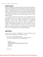
The rasterization shown in Figure 3.33 appears to have jagged edges.
This jagged appearance is the consequence of aliasing. Aliasing is the loss
of information that results from converting from a continuous curve to a
discrete set of samples. Anti-aliasing is a term that refers to a technique that
attempts to minimize aliasing artifacts.
The Silverlight anti-aliasing technique consists of sampling multiple
times per pixel and applying a box filter to produce the final pixel color.
Silverlight conceptually samples 64 times per pixel as shown in Figure 3.35.
Chapter 3: Graphics
84
Figure 3.33: Sampling a circle
From the Library of Lee Bogdanoff
Please purchase PDF Split-Merge on www.verypdf.com to remove this watermark.
ptg
The box filter averages the contribution of all samples within a rectangle
bordering the pixel to produce a final pixel color. If some partial number of
samples is in the box, Silverlight applies transparency to blend smoothly
with what is underneath the geometry as shown in Figure 3.36. This
anti-aliasing technique produces a smooth transition from inside the shape
to outside the shape along edges.
Under the Hood 85
Figure 3.34: Sampling a circle with integer sample
point coordinates
Figure 3.35: Anti-aliasing sampling pattern
From the Library of Lee Bogdanoff
Please purchase PDF Split-Merge on www.verypdf.com to remove this watermark.
ptg
Chapter 3: Graphics
86
Figure 3.36: Anti-aliased rasterization
Technical Insight
You may be wondering why there are 16 samples per pixel in the x direction
and only 4 samples per pixel in the y direction. The reason for picking this
sample pattern is that horizontal resolution is critical to being able to
render text clearly. Furthermore, horizontal resolution is computationally
cheap and vertical resolution is slower. The 16x4 sampling pattern
balances image quality and speed.
Instead of a box pattern, it is also possible to accumulate samples in a
circular pattern, weight samples unevenly, or even have a sample pattern
that extends far beyond a single pixel in size. In fact, all of these other
algorithms generate better image quality than a box filter but typically
render more slowly. The Silverlight high-resolution box filter is a choice
made to achieve good rendering performance with reasonable image
quality.
From the Library of Lee Bogdanoff
Please purchase PDF Split-Merge on www.verypdf.com to remove this watermark.
ptg
One artifact of anti-aliasing is a visible seam that sometimes results from
drawing two adjacent shapes. For example, the following two rectangles
that meet in the middle of a pixel generate a seam:
<Canvas xmlns=" /><Rectangle
Fill="Black"
Width="100.5"
Height="100.5"
/>
<Rectangle
Fill="Black"
Canvas.Left="100.5"
Width="100.5"
Height="100.5"
/>
</Canvas>
The previous XAML results in the rasterization shown in Figure 3.37.
Notice the gap between the two rectangles. The rectangles joined perfectly
in the input XAML, so why is there a seam in the rendered result?
These seams are a result of the rasterization rules described in this section.
Consider the rasterization process applied to a light gray pixel
X
shown in
Figure 3.37. Rectangle
A
is covering exactly half the samples for pixel
X.
Sil-
verlight consequently draws that pixel of Rectangle
A
with 0.5 anti-aliasing
alpha. Alpha is a term that refers to the transparency used to blend colors with
a formula such as
Under the Hood 87
Figure 3.37: Anti-aliasing seam example
From the Library of Lee Bogdanoff
Please purchase PDF Split-Merge on www.verypdf.com to remove this watermark.