Tài liệu Foundation Flash CS5 For Designers- P11 pdf
Bạn đang xem bản rút gọn của tài liệu. Xem và tải ngay bản đầy đủ của tài liệu tại đây (1.56 MB, 50 trang )
ANIMATION, PART 2
479
Figure 8-50. Poses are added through the context menu.
7.
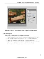
Scrub back to frame 1. Switch to the Selection tool, and move the arms and the shovel to the
position shown in Figure 8-51. If you scrub across the timeline the two arms and the shovel lower to
the ground. This tells you that poses in an armature layer can be tweened only in the armature layer.
Figure 8-51. Use the Selection tool to change a pose.
8.
Move the playhead to frame 15. Switch to the Selection tool, and extend the shovel arms.
What you need to know about this is that by changing the positions of the bones in an armature
layer, a keyframe is automatically added. There is no need to insert a pose. This may sound
rather familiar because this is exactly what happens when you change the properties of an object
in a motion layer.
9.
At this point you can continue moving through the timeline and having the machine scoop up and
dump some dirt to you can close this example and not save the changes.
www.zshareall.com
Please purchase PDF Split-Merge on www.verypdf.com to remove this watermark.
CHAPTER 8
480
Using the Bind tool
We expect that IK has sparked the creative center of your brain enough to keep you happily busy for
weeks. Believe it or not, you still have one more tool to see. The team at Adobe has made IK available not
only to symbols but also to shapes! You’ll be using the Bone tool for this exercise, but the Bind tool will
make an appearance as an important sidekick. The best way to describe IK for shapes is to consider it a
super-advanced evolution of shape tweens in combination with the shape hinting discussed in Chapter 7.
Let’s jump right in.
When it comes to IK, the distortion to be controlled is in both the stroke and fill areas of a shape.
Depending on the configuration of an IK shape, you may find that the stroke of the shape does not distort
in a pleasing way or joints move around when moving the armature. This is where the Bind tool comes
into play.
By default, the control points of a shape are connected to the bone that is nearest to them. The Bind tool
allows you to edit the connections between individual bones and the shape control points. The upshot is
you control how the stroke distorts when each bone moves.
Before we start, it might not be a bad idea to simply take a look at what effect “binding” has on a drawing.
This way, you can see, in a rather dramatic fashion, what it does and learn what to look for.
1.
Open the badBinding.fla file in your Exercise folder. When it opens, you will see two people
preparing to arm wrestle.
2.
Click the pink character’s arm to see the bones.
3.
Switch to the Selection tool and move the arm. You will notice two things, as shown in Figure
8-52. First, the elbow moves off of the table and some rather disturbing distortions occur around
the elbow joint.
Figure 8-52. Moving a bone in a shape causes distortions and unlifelike movement.
This book was purchased by
www.zshareall.com
Please purchase PDF Split-Merge on www.verypdf.com to remove this watermark.
ANIMATION, PART 2
481
4.
Open the betterBinding.fla file in your Exercise folder, and give the arm a wiggle. As you
can see, Figure 8-53, the elbow stays put, and the distortions are not as severe.
Figure 8-53. Binding, when properly applied, can add realism to movement.
Now that you have seen how binding can affect and armature, let’s get to work and start learning how to
use the Bind tool.
1.
Open the Bind.fla file in the Exercise folder for this chapter, and say hello to an earthworm, as
shown in Figure 8-54. (The correlation between a worm, bones, steam shovels, and graveyards is
purely coincidental, we assure you.) The Library for this FLA is empty, because the worm is
nothing more than a handful of shapes.
Figure 8-54. IK for shapes is brought to you by a worm.
www.zshareall.com
Please purchase PDF Split-Merge on www.verypdf.com to remove this watermark.
CHAPTER 8
482
2.
Assuming you want to drag the worm around by its head, you’ll want to draw the bones of your
armature from the opposite side of the worm. Select the Bone tool and starting from the bottom of
the shape, drag a small IK bone upward.
3.
With that first bone in place, hover over the tail of the IK bone. When the tiny black bone icon
inside the mouse cursor turns to white, you’ll know you’ve hit the right spot. Click and drag
upward to add another bone.
In this manner, keep adding small IK bones until you reach the top of the worm (see Figure 8-55).
Figure 8-55. IK bones can easily be applied to shapes.
4.
Before you give the worm a wiggle, switch to the Bind tool, and click the bottommost IK bone.
5.
This is where it gets interesting. To see we’re talking about, switch to the Zoom tool, and using the
Bind tool, marquee the bottom several bones in the tail. Now you’re ready for action.
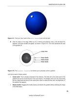
Using the Bind tool is a bit like using the Subselection tool in that it reveals a shape’s anchor points. In
Figure 8-56, you can see anchor points represented in three different ways. At the top of the figure, they
look like the sort you’ve seen in previous chapters—just small squares. At the bottom, they’re considerably
larger and thicker and appear in the form of triangles as well as squares.
www.zshareall.com
Please purchase PDF Split-Merge on www.verypdf.com to remove this watermark.
ANIMATION, PART 2
483
Figure 8-56. The Bind tool lets you manipulate anchor points.
When you select an IK bone with the Bind tool, Flash shows you which of the shape’s anchor points are
associated with that particular bone. Squares indicate an association with a single bone; triangles indicate
an association with many bones.
In this case, the bottom four anchor points—the heavy squares—are associated with the bottommost bone
only. The upper two anchor points—the heavy triangles—are associated with the bottommost bone and
with the bone immediately above it. The triangle anchor points are affected when either of their associated
bones moves.
Click any of the other IK bones in this armature, and you’ll see that Flash has done a great job of
automatically deciding which associations to make. This won’t always be the case. Thankfully, you can
override Flash’s decisions.
6.
Hold down the Ctrl (Windows) or Cmd (Mac) key, and click one of the bottom four heavy squares.
This makes it look like a normal anchor point (smaller and not bold). Still holding Ctrl (Windows)
or Cmd (Mac), click one of the heavy triangles, which also becomes a normal anchor point.
7.
Select the next IK bone, and you’ll see that the triangle anchor is back. but now it’s a heavy
square. That makes sense: before step 6, this anchor was associated with two bones (triangle),
but now it’s associated with only this one (square).
8.
Select the bottommost bone again, and, without holding down Ctrl (Windows) or Cmd (Mac), click
the anchor point that was previously a heavy square. Drag it toward the bone (see Figure 8-57)
and release. That anchor point is now reassociated with the bone.
9.
Click another bone, and then click this one again. You’ll see the heavy square as it originally was,
along with its companions.
www.zshareall.com
Please purchase PDF Split-Merge on www.verypdf.com to remove this watermark.
CHAPTER 8
484
10.
To reassociate the formerly triangle anchor point, use the Bind tool to select the appropriate
anchor, and then press and hold Ctrl (Windows) or Cmd (Mac) while you drag it to the
bottommost bone. As you do, you’ll see an association line in the upper bone as well as the
diagonal association line created by your dragging (see Figure 8-58).
Figure 8-57. Click and drag an anchor point to associate it with a bone.
Figure 8-58. Press Ctrl (Windows) or Cmd (Mac) while dragging to associate an anchor point with more
than one bone.
www.zshareall.com
Please purchase PDF Split-Merge on www.verypdf.com to remove this watermark.
ANIMATION, PART 2
485
11.
Save the file. (You’re going to continue with it in the next exercise.)
Use the Bind tool to fine-tune your shape armatures, just as you would use shape hints to fine-tune a
shape tween. Any anchor points not associated with an IK bone are ignored when the armature is
manipulated.
You can animate shape armatures in the same way as symbol armatures—and you’re about to do just
that—which will introduce you to two “gotchas” of this feature.
When it comes to IK with shapes, two limitations leap to mind:
Shape armatures don’t manipulate gradient and bitmap fills.
Complex shapes cannot be boned, so keep your overall anchor point count to a minimum.
Let’s explore these limitations before moving on to a full-scale IK animation exercise.
Shape IK and fills
To see what we mean about fills, continuing with the Bind.fla from the previous exercise, use the
Selection tool to give your worm a wiggle. It’s fun to do, because the shape responds in a very worm-
like way. When you’re finished, click the stage to deselect the bones and the shape’s bounding box.
The shape looks great, but as you can see in Figure 8-59, the gradient fill, which gave the worm a slightly
rounded look, hasn’t bent along with the shape. This tells you to stick with solid fills for shape armatures.
Figure 8-59. Shape armatures don’t affect gradient or bitmap fills.
Shape IK and anchor points
Let’s see how the number of anchor points affects shape IK:
1.
Open the WaveSwiss.fla file in this chapter’s Exercise folder. You’ll see a drawing of the Swiss
flag with a shape armature in place.
www.zshareall.com
Please purchase PDF Split-Merge on www.verypdf.com to remove this watermark.
CHAPTER 8
486
2.
Drag the right side of the armature up and down to wave the flag (see Figure 8-60).
Figure 8-60. There is a definite relationship between armatures and vector points when it comes to IK in
Flash.
3.
Open the WaveAmerican.fla file from the same folder. In this file, the armature hasn’t been
added yet.
4.
Use the Selection tool to select the whole shape, and then switch to the Bone tool and try to
add an IK bone.
Instead of a new armature, you’ll see the alert box in Figure 8-61 telling you the shape is too complex.
Want to know the culprit?
Figure 8-61. Shape complexity also comes into play when it comes to IK in Flash.
5.
Switch to the Subselection tool, and draw a selection around the whole shape.
www.zshareall.com
Please purchase PDF Split-Merge on www.verypdf.com to remove this watermark.
ANIMATION, PART 2
487
Each of those 50 stars is composed of 10 anchor points. That’s 500 points already, and that doesn’t
include the stripes. We’re not sure where the official line is drawn, but 500+ anchor points is too much.
Your solutions are to either optimize the graphic, which we cover in Chapter 15, or convert the entire flag
to a movie clip. Our suggestion is go the movie clip route because optimizing will reduce the number of
vector points but not sufficiently to avoid a repeat of this warning.
Your turn: animate a fully rigged IK model
We figure you appreciate worms, bending trees, steam shovels, and skeleton hands as much as the next
designer (and so do we!). But surely, your thoughts have already wandered toward more complex
implementations. We suspect you’re wondering if the IK tools are useful for more than a few fingers. What
about a whole body? The answer to these questions is yes, and you’re about to find out firsthand. In this
final exercise of the chapter, you’ll expand on what you learned in previous sections by rigging up a
character with arms and legs and then animating it against a backdrop of hand-sketched poses. Let’s do it.
1.
Open the Richard.fla file from the Exercise folder for this chapter. You’ll see an assembled
collection of symbols in the likeness of Richard (see Figure 8-62), one of the regular characters in
Steve Napierski’s web comic “The Outer Circle” (www.theoutercircle.com/).
The authors would like to give Steve a hearty thanks for letting us use his artwork! See
more at
www.pierski.com/
.
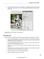
Figure 8-62. Meet Richard. Give him a hug. You’re going to make Richard jump.
www.zshareall.com
Please purchase PDF Split-Merge on www.verypdf.com to remove this watermark.
CHAPTER 8
488
2.
Select Edit (Flash)
➤
Preferences, and click the Drawing choice in the Category area.
Deselect the IK Bone tool: Auto Set Transformation Point check box. As described
in the “A note about bone preferences” section earlier, this means you’ll be the one deciding
where to place your bone heads and tails, and you’ll adjust them afterward.
3.
Select the Oval tool and, in the Richard layer, draw a small circle about 22 pixels 22 pixels
near one of the character’s hands. Select the shape and convert it to a graphic symbol named
handle. This is going to be your “ghost handle,” which lets you constrain the hands, feet, and
head.
4.
Drag additional instances of the handle symbol from the Library to the stage, positioning them
near the Richard’s other hand, his feet, and his head, as shown in Figure 8-63. In this exercise,
Richard’s chest will act as the starting point for every new chain of bones, just as the skeleton’s
palm did in earlier exercises.
Figure 8-63. Make sure to include extra symbols to allow for rotation constraints.
5.
Select the Bone tool, and then click and drag a bone from the torso symbol to one of the upper
leg symbols. Be sure to release the bone’s tail low enough on the upper leg that it clears the
bounding box of the torso (see the bounding box in Figure 8-64, and note how the bone tail falls
below it). Even though this puts the bone tail lower than it should on the leg symbol—effectively
moving the “hip” into the thigh—you’ll be able to readjust it in just a moment.
www.zshareall.com
Please purchase PDF Split-Merge on www.verypdf.com to remove this watermark.
ANIMATION, PART 2
489
Figure 8-64. Make sure the bone’s tail clears the bounding box of the torso symbol.
The fact that these symbols overlap is part of the reason we had you deselect Auto Set
Transformation Point in step 2. Although not always a problem, in this case, the obscured symbol
rotation points make it harder for Flash to decide on its own where new chains of bones should begin.
6.
Just as you did earlier for the knuckles, continue adding a new bone that connects the upper leg
to the lower leg, the lower leg to the ankle, the ankle to the foot, and finally the foot to the foot’s
ghost handle. Feel free to zoom the stage—particularly for the ankle! —if necessary.
7.
Select the Free Transform tool, and then click the stage to deselect the armature itself.
8.
Click each symbol in turn, from the ghost handle back up to the torso, and adjust the
transformation point so that it sits over the symbol’s registration point. To do this, click the white
circle (transformation point), drag it to the small plus sign (registration point), and then release.
Selecting Snap to Objects in the Tools panel will make this task easier for you.
9.
After you’ve adjusted the transformation point for each boned symbol, select the Bone tool again,
and click the head of the torso’s existing bone to begin a new chain of bones down the other leg.
Follow this with a repeat of the Free Transform tool adjustments of the relevant symbols’
transformation points.
10.
Obviously, the arms need the same treatment, as does the head. Starting from the same
gathering of torso bones each time, use the Bone tool to create new bone chains from the torso
to upper arm, lower arm, hand, to ghost handle on both sides, and then from torso to head to
ghost handle at the top of the character. When you’re finished, revisit all relevant symbols with
the Free Transform tool to reposition transformation points over their corresponding
registration points. Your armature should look like the one shown in Figure 8-65.
www.zshareall.com
Please purchase PDF Split-Merge on www.verypdf.com to remove this watermark.
CHAPTER 8
490
Figure 8-65. A complete IK rig
At this point, Richard is nearly ready for his calisthenics. First, we need a few rotation constraints.
11.
Using the Selection tool, click any of the torso bones and deselect the Enabled option in the
Joint: Rotation area of the Properties panel. Because all the torso bones share the same
head, this action will disable rotation for the whole body.
12.
Zoom the stage, if necessary, and disable rotation for the ankle bones.
13.
Add rotation constraints to the remaining bones according to your preferences. For example,
select the lower leg’s bone, and in the Properties panel, select the Constrain option and
adjust the Min and Max values to keep the knee from bending backward.
When you’re finished, the Timeline‘s original Richard layer will have long since been emptied, because
every symbol was moved to the automatically created armature layer as it was associated with a bone.
14.
Rename the Richard layer to poses.
15.
Select File
➤
Import
➤
Import to Stage, and import the jumping.jpg file in this chapter’s
Exercise folder. This JPG features a number of hand-drawn poses you can use as guides to
manipulate the armature. Position the imported JPG slightly to the right, so that it appears behind
Richard, and then lock the poses layer.
16.
Select Edit
➤
Select All to select the armature’s symbols.
This book was purchased by
www.zshareall.com
Please purchase PDF Split-Merge on www.verypdf.com to remove this watermark.
ANIMATION, PART 2
491
17.
Open the Transform panel (Window
➤
Transform). Make sure the Constrain option in the
Transform panel is selected (the chain icon is not broken), and resize the fully selected
armature to approximately 75 percent, as shown in Figure 8-66. This matches the character’s
size with the hand-drawn poses.
Figure 8-66. Resize the armature, and all its symbols, to the hand-drawn guides, and you’re set.
When you release the mouse after scrubbing, the Transform panel will seem to indicate that the
armature is still scaled to 100 percent, but if you select each symbol individually, the Transform panel will
correctly show the smaller scale you chose in step 18.
Richard’s jump should take about one second. Because the movie’s frame rate is 24 fps, that means 24
frames is fine.
18.
Hover near the right edge of the of the armature’s single frame until the icon turns into a double-
headed arrow. Drag out the armature span until it reaches frame 24.
19.
Right-click (Windows) or Control+click (Mac) the poses layer at frame 24, and select Insert
Frame from the context menu. This matches up the JPEG to the time span of the armature layer.
20.
We’re about to cut you loose, so here’s the basic gist of what you’ll repeat until the sequence is
finished:
a. Unlock the poses layer and slide the JPG to the left in order to position the next pose under
the armature. Once the JPEG is moved, lock the poses layer again.
b. Drag the playhead six frames to the right (one-fourth of the armature span, because there
are four poses after the first drawing).
c. Use the Selection tool to manipulate the character’s body parts so they match the hand-
drawn pose.
www.zshareall.com
Please purchase PDF Split-Merge on www.verypdf.com to remove this watermark.
CHAPTER 8
492
Here are two important tips:
Depending on how you might have constrained your joints, you may not be able to match the
drawing perfectly. Treat the drawings as rough guides. In Figure 8-63, for example, you can
see that our elbows don’t match the pose at all—they’re bent in the opposite direction! Just
have fun with it.
You will often need to move the whole armature at once. To accomplish this, hold down the
Ctrl (Windows) or Cmd (Mac) key, and click the current frame of the armature layer. Doing so
simultaneously selects all the armature’s symbols in the chosen frame. At this point, slowly
tap the keyboard’s arrow keys to move the armature. If you hold down Shift while pressing
the arrow keys, you can move in 10-pixel increments, which makes it go faster.
21.
After you’ve finished posing the armature at frames 6, 12, 18, and 24, right-click (Windows) or
Control+click (Mac) the poses layer and convert it to a guide layer. This will keep it from showing
when you publish the SWF. (Alternatively, you could hide the poses layer and configure your
preferences to omit hidden layers from the SWF—see the “Using layers” section of Chapter 1—or
simply delete the poses layer.)
22.
Double-click the handle symbol in the Library to open it in the Symbol Editor. Change the
opacity of its fill color to 0%, to make the ghost handles invisible when you publish.
23.
Save your file, and test the movie. If you like, compare your work with the completed
Richard.fla file in this chapter’s Complete folder.
Inspiration is everywhere
We started this chapter with a mention of some inspirational early Flash animation, so it’s fitting to finish
with a few more current resources.
Chris Georgenes () is one of the most talented Flash animators we know
and a friendly guy to boot! His forum has become an immensely
popular meeting place for Flash cartoonists and animators, from beginner to pro. So, visit his
forum, sign up (it’s free), and bring along your artwork, demo reels, and questions. You’ll find
literally thousands of eager participants ready to share their Flash-based tips and tricks.
For a look at some jaw-droppingly amazing, multiple award-winning Flash cartoons, check out the
“Animation” section of Adam Phillips’s website. Adam was happy to
lend us a screenshot from “Waterlollies” (see Figure 8-67). He draws and animates all his artwork
directly in Flash. When you see what’s possible with the authoring tool, you might just think (as
one of the authors does), “When I grow up, I want to be Adam Phillips.”
www.zshareall.com
Please purchase PDF Split-Merge on www.verypdf.com to remove this watermark.
ANIMATION, PART 2
493
Figure 8-67. A scene from Adam Phillips’s “Waterlollies” (www.biteycastle.com)
For an additional 360 pages of top-notch Flash animation how-to, check out Foundation Flash
Cartoon Animation (friends of ED, 2007), by Tim Jones, Barry Kelly, Allan Rosson, and David
Wolfe (www.friendsofed.com/book.html?isbn=9781590599129). This book was written for
Flash CS3, so it covers only the technical content discussed in Chapter 7, but it goes on to
elaborate on industry practices, including Library organization, storyboarding and animatics,
frame-by-frame animation, and integration with After Effects.
What you have learned
In this chapter, you learned the following:
How to use the Motion Editor panel
That even though the new tweening model is intended for the Motion Editor panel, the
Timeline panel continues to be useful for motion tweens
How to use and configure advanced easing graphs and how to create your own
How to navigate property keyframes in the Motion Editor and Timeline panels
How to change the duration of a tween span
How to manipulate and reuse motion paths, with or without the Motion Presets panel
www.zshareall.com
Please purchase PDF Split-Merge on www.verypdf.com to remove this watermark.
CHAPTER 8
494
How IK works in Flash
How to use the Bone and Bind tools
How to use the Spring feature
Tips on improving your IK bone rigging workflow
How to animate an IK armature
This has been a rather intense chapter, but you have to admit there is some seriously cool animation stuff
in Flash CS5. We started by walking you through the Motion Editor, including motion paths. Up to this
point in the book, the Motion Editor was something you “visited.” Now you have learned how valuable
a tool it will be as you strengthen your Flash skills.
From there, we took you deep into the new inverse kinematics features of Flash CS5. Starting with the
Bone tool and a skeleton, we guided you through this subject. By animating trees in a wind storm, steam
shovels, flags waving in the breeze, steam engines, and an honest-to-goodness real cartoon character,
you discovered the power of inverse kinematics and quite a few of the gotchas and workarounds being
developed as the Flash industry adjusts to this new animation capability.
As you went through this chapter, you were probably thinking, “This is all well and good in a flat space, but
where’s the 3D?” Great question. Why don’t you turn the page and find out.
www.zshareall.com
Please purchase PDF Split-Merge on www.verypdf.com to remove this watermark.
495
Chapter 9
Flash Has a Third Dimension
Designers had been asking for 3D manipulation tools in Flash for a long time. In fact, this feature has been
requested in some form or another since the beginning of the product line. That makes sense if you
consider that the mid-1990s promise of Virtual Reality Modeling Language (VRML) gave web surfers a
taste of 3D before Flash ever hit the market. VRML was a great idea, but it was ahead of its time and,
sadly, didn’t go very far. In any case, it was more of a programmer’s pursuit than something a designer
would want to grapple with.
Then came Flash, which sparked an explosion of stylish 2D designs that began to reshape what the web
experience meant. Over the years, intrepid designers began experimenting with ways to simulate three
dimensions in their SWFs. They used centuries-old techniques to accomplish these goals—for example,
increasing the size of an object to “move it forward”—which were the same practices used in real-life
painting and sketching. Nothing in the Flash interface provided direct assistance. This all changed in Flash
CS4. The requested tools arrived, and they’re here to stay in CS5. If you’ll pardon the pun, they open a
whole new dimension in creative potential.
Here’s what we’ll cover in this chapter:
Understanding the 3D environment
Using the 3D tools
Positioning symbols in 3D space
The following files are used in this chapter (located in Chapter09/ExerciseFiles_Ch09/Exercise/):
www.zshareall.com
Please purchase PDF Split-Merge on www.verypdf.com to remove this watermark.
CHAPTER 9
496
Amsterdam.fla
FigurineSmall.jpg
Figurine.jpg
Amsterdam01.jpg
SpaceFinal.png
Space.fla
swingDoors.fla
AirheadMail.fla
3DCube.fla
The source files are available online at www.friendsofED.com/download.html?isbn=1430229940.
What you’ll learn in this chapter pertains to the 3D-related tools in the Flash CS5 Tools panel, along with
some workflow suggestions to help you get the most out of them. This will be enough to introduce you to a
new playground.
If you want to supplement the benefits of the new 3D tools with older techniques, consider checking out
Flash 3D Cheats Most Wanted by Aral Balkan, Josh Dura, et al. (friends of ED, 2003). To learn about
simulating 3D with ActionScript 3.0, see Chapters 15 through 17 of Foundation ActionScript 3.0 Animation:
Making Things Move! by Keith Peters (friends of ED, 2007). For the perfect introduction to using a 3D
engine (Away3D) to create “real” 3D in Flash, see The Essential Guide to 3D in Flash by Richard Olsson
and Rob Bateman (friends of ED, 2010).
What 3D really means in Flash (and what it doesn’t)
When it comes to 3D in Flash, consider this feature as you would pizza. No matter what the server brings
from the kitchen, you’re going to love it. Capisce? Good. Now that you’re thinking of a delicious pie with all
your favorite toppings, tease your mind back to Flash for a moment. Between bites, wrap your brain
around three levels of wow factor:
Good (“Hey, this is super cool!”)
Better (“My jaw just hit the floor!”)
Best (“Somebody bring me oxygen!”)
Game consoles like the Wii, PlayStation 3, and Xbox 360 have redefined what consumers expect in terms
of 3D interactivity. This is the bring-me-oxygen stuff—the Best level—which isn’t available in Flash. We
need to mention that right out of the gate. (Hey, are you going to eat that pepperoni?)
On the design side of things, you would need specialized 3D modeling software to produce that sort of
content for game consoles, television, or film. We’re talking about software like Maya, 3Ds Max, Blender,
or Cinema 4D. These industrial-strength powerhouses are designed specifically for the task and are
www.zshareall.com
Please purchase PDF Split-Merge on www.verypdf.com to remove this watermark.
FLASH HAS A THIRD DIMENSION
497
capable of turning out extremely complex, high-resolution output. Examples include everything from
Hollywood aliens, dragons, and virtual stunts, all the way to vehicle mock-ups, such as the Hot Rod
created by Belgian CG artist Laurens Corijn for cg.activtutsplus.com, shown in Figure 9-1.
Figure 9-1. Highly complex 3D models are created in software designed for the task, which doesn’t
include Flash (car modeled by Laurens Corijn).
For better or worse, advanced 3D modeling is not the sort of field trip you’ll be taking in Flash CS5—at
least, not with the new drawing tools. Don’t let that get you down, though. For you code jockeys, be aware
that ActionScript does give you a surprising range of possibilities, but you’ll probably want to use third-
party code libraries to pull it off.
For the jaw-dropping stuff—the Better level—you’ll want to check out Papervision3D (www.
Papervision3D.org/). This is open source software (created by core team members Carlos Ulloa, Ralph
Hauwert, John Grden, Tim Knip, and Andy Zupko) consisting of a framework of ActionScript 3.0 and 2.0
class files. Papervision3D allows programmers to create a range of 3D primitives (basic shapes, from
which other shapes can be built), and even import COLLADA (an open XML standard) data files from
external modeling applications, and then bring those models to life in complex ways, as shown in Figure
9-2. Yup, that’s Flash, and every fish, including the shark, is interactive. In addition, the entire scene gives
you a complete 360-degree view of the reef when you drag the mouse. Interactive. In many ways, this is
comparable to VRML.
www.zshareall.com
Please purchase PDF Split-Merge on www.verypdf.com to remove this watermark.
CHAPTER 9
498
Figure 9-2. An example of Papervision3D content
If you’re experienced with previous versions of Flash, you may have heard of Swift 3D (www.erain.com).
Swift 3D is a best-of-breed, low-cost modeler closely integrated with Flash in that it exports models as
SWFs. These SWFs can then be loaded or imported into your normal work files and used to simulate
three-dimensional objects. The latest version of Swift 3D even exports to Papervision3D, so you’re in good
hands with this product. Designers typically import Swift 3D assets as elements of otherwise two-
dimensional layouts. That workflow is every bit as useful in Flash CS4 as it has been in the past, but it’s
not the topic we’re covering here.
What you’ll learn about in this chapter is the super-cool stuff—the Good level—and a great place to start if
you’re new to nonscripted 3D in Flash (which pretty much means anyone using Flash CS5 for the first
time). We won’t be covering 3D in terms of ActionScript. It’s simply a topic that merits its own book (such
as The Essential Guide to 3D in Flash, mentioned earlier), and we again direct your attention to
www.Papervision3D.org or www.away3d.com. What you are about to discover, behind that heavenly
melted mozzarella, is a pair of shiny tools that first appeared in Flash CS4 that give you direct three-
dimensional manipulation of your symbols. But first, we need to cover a bit of theory.
Understanding the vanishing point
When you open your eyelids and cast your gaze ahead, even if all you can see are the tweed walls of your
cubicle, you have a horizon in front of you. Turn your head, and it’s still there. The horizon might be
hidden, but the principles of perspective still apply, just as gravity still applies even when you climb a tree
www.zshareall.com
Please purchase PDF Split-Merge on www.verypdf.com to remove this watermark.