Tài liệu Windows Internals covering windows server 2008 and windows vista- P19 doc
Bạn đang xem bản rút gọn của tài liệu. Xem và tải ngay bản đầy đủ của tài liệu tại đây (776.24 KB, 50 trang )
890
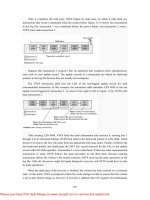
After it completes the redo pass, NTFS begins its undo pass, in which it rolls back any
transactions that weren’t committed when the system failed. Figure 11-55 shows two transactions
in the log file; transaction 1 was committed before the power failure, but transaction 2 wasn’t.
NTFS must undo transaction 2.
Suppose that transaction 2 created a file, an operation that comprises three suboperations,
each with its own update record. The update records of a transaction are linked by backward
pointers in the log file because they are usually not contiguous.
The NTFS transaction table lists the LSN of the last-logged update record for each
noncommitted transaction. In this example, the transaction table identifies LSN 4049 as the last
update record logged for transaction 2. As shown from right to left in Figure 11-56, NTFS rolls
back transaction 2.
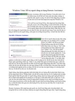
After locating LSN 4049, NTFS finds the undo information and executes it, clearing bits 3
through 9 in its allocation bitmap. NTFS then follows the backward pointer to LSN 4048, which
directs it to remove the new file name from the appropriate file name index. Finally, it follows the
last backward pointer and deallocates the MFT file record reserved for the file, as the update
record with LSN 4046 specifies. Transaction 2 is now rolled back. If there are other noncommitted
transactions to undo, NTFS follows the same procedure to roll them back. Because undoing
transactions affects the volume’s file system structure, NTFS must log the undo operations in the
log file. After all, the power might fail again during the recovery, and NTFS would have to redo
its undo operations!
When the undo pass of the recovery is finished, the volume has been restored to a consistent
state. At this point, NTFS is prepared to flush the cache changes to disk to ensure that the volume
is up to date. Before doing so, however, it executes a callback that TxF registers for notifications
Please purchase PDF Split-Merge on www.verypdf.com to remove this watermark.
891
of LFS flushes. Because TxF and NTFS both use write-ahead logging, TxF must flush its log
through CLFS before the NTFS log is flushed to ensure consistency of its own metadata. (And
similarly, the TOPS file must be flushed before the CLFS-managed log files.) NTFS then writes
an “empty” LFS restart area to indicate that the volume is consistent and that no recovery need be
done if the system should fail again immediately. Recovery is complete.
NTFS guarantees that recovery will return the volume to some preexisting consistent state,
but not necessarily to the state that existed just before the system crash. NTFS can’t make that
guarantee because, for performance, it uses a “lazy commit” algorithm, which means that the log
file isn’t immediately flushed to disk each time a “transaction committed” record is written.
Instead, numerous “transaction committed” records are batched and written together, either when
the cache manager calls the LFS to flush the log file to disk or when the LFS writes a checkpoint
record (once every 5 seconds) to the log file. Another reason the recovered volume might not be
completely up to date is that several parallel transactions might be active when the system crashes
and some of their “transaction committed” records might make it to disk whereas others might not.
The consistent volume that recovery produces includes all the volume updates whose “transaction
committed” records made it to disk and none of the updates whose “transaction committed”
records didn’t make it to disk.
NTFS uses the log file to recover a volume after the system fails, but it also takes advantage
of an important “freebie” it gets from logging transactions. File systems necessarily contain a lot
of code devoted to recovering from file system errors that occur during the course of normal file
I/O. Because NTFS logs each transaction that modifies the volume structure, it can use the log file
to recover when a file system error occurs and thus can greatly simplify its error handling code.
The “log file full” error described earlier is one example of using the log file for error recovery.
Most I/O errors a program receives aren’t file system errors and therefore can’t be resolved
entirely by NTFS. When called to create a file, for example, NTFS might begin by creating a file
record in the MFT and then enter the new file’s name in a directory index. When it tries to allocate
space for the file in its bitmap, however, it could discover that the disk is full and the create
request can’t be completed. In such a case, NTFS uses the information in the log file to undo the
part of the operation it has already completed and to deallocate the data structures it reserved for
the file. Then it returns a “disk full” error to the caller, which in turn must respond appropriately to
the error.
11.8.4 NTFS Bad-Cluster Recovery
The volume manager included with Windows (VolMgr) can recover data from a bad sector
on a fault-tolerant volume, but if the hard disk doesn’t use the SCSI protocol or runs out of spare
sectors, a volume manager can’t perform sector sparing to replace the bad sector. (See Chapter 8
for more information on the volume manager.) When the file system reads from the sector, the
volume manager instead recovers the data and returns the warning to the file system that there is
only one copy of the data.
The FAT file system doesn’t respond to this volume manager warning. Moreover, neither
FAT nor the volume manager keeps track of the bad sectors, so a user must run the Chkdsk or
Please purchase PDF Split-Merge on www.verypdf.com to remove this watermark.
892
Format utility to prevent the volume manager from repeatedly recovering data for the file system.
Both Chkdsk and Format are less than ideal for removing bad sectors from use. Chkdsk can take a
long time to find and remove bad sectors, and Format wipes all the data off the partition it’s
formatting.
In the file system equivalent of a volume manager’s sector sparing, NTFS dynamically
replaces the cluster containing a bad sector and keeps track of the bad cluster so that it won’t be
reused. (Recall that NTFS maintains portability by addressing logical clusters rather than physical
sectors.) NTFS performs these functions when the volume manager can’t perform sector sparing.
When a volume manager returns a bad-sector warning or when the hard disk driver returns a
bad-sector error, NTFS allocates a new cluster to replace the one containing the bad sector. NTFS
copies the data that the volume manager has recovered into the new cluster to reestablish data
redundancy.
Figure 11-57 shows an MFT record for a user file with a bad cluster in one of its data runs as
it existed before the cluster went bad. When it receives a bad-sector error, NTFS reassigns the
cluster containing the sector to its bad-cluster file. This prevents the bad cluster from being
allocated to another file. NTFS then allocates a new cluster for the file and changes the file’s
VCN-to-LCN mappings to point to the new cluster. This bad-cluster remapping (introduced earlier
in this chapter) is illustrated in Figure 11-57. Cluster number 1357, which contains the bad sector,
must be replaced by a good cluster.
Bad-sector errors are undesirable, but when they do occur, the combination of NTFS and the
volume manager provides the best possible solution. If the bad sector is on a redundant volume,
the volume manager recovers the data and replaces the sector if it can. If it can’t replace the sector,
it returns a warning to NTFS, and NTFS replaces the cluster containing the bad sector.
If the volume isn’t configured as a redundant volume, the data in the bad sector can’t be
recovered. When the volume is formatted as a FAT volume and the volume manager can’t recover
the data, reading from the bad sector yields indeterminate results. If some of the file system’s
control structures reside in the bad sector, an entire file or group of files (or potentially, the whole
disk) can be lost. At best, some data in the affected file (often, all the data in the file beyond the
bad sector) is lost. Moreover, the FAT file system is likely to reallocate the bad sector to the same
or another file on the volume, causing the problem to resurface. Like the other file systems, NTFS
can’t recover data from a bad sector without help from a volume manager. However, NTFS
greatly contains the damage a bad sector can cause. If NTFS discovers the bad sector during a read
Please purchase PDF Split-Merge on www.verypdf.com to remove this watermark.
893
operation, it remaps the cluster the sector is in, as shown in Figure 11-58. If the volume isn’t
configured as a redundant volume, NTFS returns a “data read” error to the calling program.
Although the data that was in that cluster is lost, the rest of the file—and the file system—remains
intact; the calling program can respond appropriately to the data loss, and the bad cluster won’t be
reused in future allocations. If NTFS discovers the bad cluster on a write operation rather than a
read, NTFS remaps the cluster before writing and thus loses no data and generates no error.
The same recovery procedures are followed if file system data is stored in a sector that goes
bad. If the bad sector is on a redundant volume, NTFS replaces the cluster dynamically, using the
data recovered by the volume manager. If the volume isn’t redundant, the data can’t be recovered,
and NTFS sets a bit in the volume file that indicates corruption on the volume. The NTFS Chkdsk
utility checks this bit when the system is next rebooted, and if the bit is set, Chkdsk executes,
fixing the file system corruption by reconstructing the NTFS metadata.
In rare instances, file system corruption can occur even on a fault-tolerant disk configuration.
A double error can destroy both file system data and the means to reconstruct it. If the system
crashes while NTFS is writing the mirror copy of an MFT file record—of a file name index or of
the log file, for example—the mirror copy of such file system data might not be fully updated. If
the system were rebooted and a bad-sector error occurred on the primary disk at exactly the same
location as the incomplete write on the disk mirror, NTFS would be unable to recover the correct
data from the disk mirror. NTFS implements a special scheme for detecting such corruptions in
file system data. If it ever finds an inconsistency, it sets the corruption bit in the volume file,
which causes Chkdsk to reconstruct the NTFS metadata when the system is next rebooted.
Because file system corruption is rare on a fault-tolerant disk configuration, Chkdsk is seldom
needed. It is supplied as a safety precaution rather than as a first-line data recovery strategy.
Please purchase PDF Split-Merge on www.verypdf.com to remove this watermark.
894
The use of Chkdsk on NTFS is vastly different from its use on the FAT file system. Before
writing anything to disk, FAT sets the volume’s dirty bit and then resets the bit after the
modification is complete. If any I/O operation is in progress when the system crashes, the dirty bit
is left set and Chkdsk runs when the system is rebooted. On NTFS, Chkdsk runs only when
unexpected or unreadable file system data is found and NTFS can’t recover the data from a
redundant volume or from redundant file system structures on a single volume. (The system boot
sector is duplicated, as are the parts of the MFT required for booting the system and running the
NTFS recovery procedure. This redundancy ensures that NTFS will always be able to boot and
recover itself.)
Table 11-9 summarizes what happens when a sector goes bad on a disk volume formatted for
one of the Windows-supported file systems according to various conditions we’ve described in
this section.
If the volume on which the bad sector appears is a fault-tolerant volume (a mirrored or
RAID-5 volume) and if the hard disk is one that supports sector sparing (and that hasn’t run out of
spare sectors), it doesn’t matter which file system you’re using (FAT or NTFS). The volume
manager replaces the bad sector without the need for user or file system intervention. If a bad
sector is located on a hard disk that doesn’t support sector sparing, the file system is responsible
for replacing (remapping) the bad sector or—in the case of NTFS—the cluster in which the bad
sector resides. The FAT file system doesn’t provide sector or cluster remapping. The benefits of
NTFS cluster remapping are that bad spots in a file can be fixed without harm to the file (or harm
to the file system, as the case may be) and that the bad cluster won’t be reallocated to the same or
another file.
11.8.5 Self-Healing
With today’s multiterabyte storage devices, taking a volume offline for a consistency check
can result in a service outage of many hours. Recognizing that many disk corruptions are localized
Please purchase PDF Split-Merge on www.verypdf.com to remove this watermark.
895
to a single file or portion of metadata, NTFS implements a self-healing feature to repair damage
while a volume remains online. When NTFS detects corruption, it prevents access to the damaged
file or files and creates a system worker thread that executes Chkdsklike corrections to the
corrupted data structures, allowing access to the repaired files when it has finished. Access to
other files continues normally during this operation, minimizing service disruption.
You can use the fsutil repair set command to view and set a volume’s repair options, which
are summarized in Table 11-10. The Fsutil utility uses the FSCTL_SET_REPAIR file system
control code to set these settings, which are saved in the VCB for the volume.
In all cases, including when the visual warning is disabled (the default), NTFS will log any
selfhealing operation it undertook in the System event log.
Apart from periodic automatic self-healing, NTFS also supports manually initiated
selfhealing cycles through the FSCTL_INITIATE_REPAIR and FSCTL_WAIT_FOR_REPAIR
control codes, which can be initiated with the fsutil repair initiate and fsutil repair wait commands.
This allows the user to force the repair of a specific file and to wait until repair of that file is
complete.
To check the status of the self-healing mechanism, the FSCTL_QUERY_REPAIR control
code or the fsutil repair query command can be used, as shown here:
1. C:\>fsutil repair query c:
2. Self healing is enabled for volume c: with flags 0x1.
3. flags: 0x01 - enable general repair
4. 0x08 - warn about potential data loss
5. 0x10 - disable general repair and bugcheck once on first corruption
11.9 Encrypting File System Security
EFS security relies on cryptography support. The first time a file is encrypted, EFS assigns
the account of the user performing the encryption a private/public key pair for use in file
encryption. Users can encrypt files via Windows Explorer by opening a file’s Properties dialog
box, clicking Advanced, and then selecting the Encrypt Contents To Secure Data option, as shown
in Figure 11-59. Users can also encrypt files via a command-line utility named cipher. Windows
automatically encrypts files that reside in directories that are designated as encrypted directories.
When a file is encrypted, EFS generates a random number for the file that EFS calls the file’s file
Please purchase PDF Split-Merge on www.verypdf.com to remove this watermark.
896
encryption key (FEK). EFS uses the FEK to encrypt the file’s contents with a stronger variant of
the Data Encryption Standard (DES) algorithm—Triple-DES (3DES) or Advanced Encryption
Standard (AES). EFS stores the file’s FEK with the file but encrypts the FEK with the user’s EFS
public key by using the RSA public key–based encryption algorithm. After EFS completes these
steps, the file is secure: other users can’t decrypt the data without the file’s decrypted FEK, and
they can’t decrypt the FEK without the private key.
eFS FeK Key Strength
The default FEK encryption algorithm is AES. The Windows AES algorithm uses 256-bit
keys. Use of 3DES allows access to larger sized keys, so if you require greater key strength you
can enable 3DES encryption in one of two ways: either as the algorithm for all system
cryptographic services or just for EFS.
To have 3DES be the encryption algorithm for all system cryptographic services, open the
Local Security Policy Editor by entering secpol.msc in the Run dialog box from the Start menu
and open the Security Options node under Local Policies. View the properties of System
Cryptography: Use FIPS Compliant Algorithms For Encryption, Hashing And Signing, and enable
it.
To enable 3DES for EFS only, create the DWORD value HKLM\SOFTWARE\Microsoft
\Windows NT\CurrentVersion\EFS\AlgorithmID, set it to 0x6603, and reboot.
EFS uses a private/public key algorithm to encrypt FEKs. To encrypt file data, EFS uses AES
or 3DES because both are symmetric encryption algorithms, which means that they use the same
key to encrypt and decrypt data. Symmetric encryption algorithms are typically very fast, which
makes them suitable for encrypting large amounts of data, such as file data. However, symmetric
encryption algorithms have a weakness: you can bypass their security if you obtain the key. If
multiple users want to share one encrypted file protected only by AES or 3DES, each user would
require access to the file’s FEK. Leaving the FEK unencrypted would obviously be a security
problem, but encrypting the FEK once would require all the users to share the same FEK
decryption key—another potential security problem.
Keeping the FEK secure is a difficult problem, which EFS addresses with the public
key–based half of its encryption architecture. Encrypting a file’s FEK for individual users who
access the file lets multiple users share an encrypted file. EFS can encrypt a file’s FEK with each
user’s public key and can store each user’s encrypted FEK with the file. Anyone can access a
Please purchase PDF Split-Merge on www.verypdf.com to remove this watermark.
897
user’s public key, but no one can use a public key to decrypt the data that the public key
encrypted.
The only way users can decrypt a file is with their private key, which the operating system
must access. A user’s private key decrypts the user’s encrypted copy of a file’s FEK. Public
key–based algorithms are usually slow, but EFS uses these algorithms only to encrypt FEKs.
Splitting key management between a publicly available key and a private key makes key
management a little easier than symmetric encryption algorithms do and solves the dilemma of
keeping the FEK secure.
Windows stores a user’s private keys in the user’s profile directory (typically under \Users)
within the AppData\Roaming\Microsoft\Crypto\RSA subdirectory. To protect private keys,
Windows encrypts all files within the RSA folder with a random symmetric key called the user’s
master key. The master key is 64 bytes in length and is generated by a strong random number
generator. The master key is also stored in the user’s profile under the AppData\Roaming
\Microsoft\Protect directory and is 3DES-encrypted with a key that’s in part based on the user’s
password. When a user changes his or her password, master keys are automatically unencrypted
and re-encrypted using the new password.
Several components work together to make EFS work, as the diagram of EFS architecture in
Figure 11-60 shows. EFS support is merged into the NTFS driver. Whenever NTFS encounters an
encrypted file, NTFS executes EFS functions that it contains. The EFS functions encrypt and
decrypt file data as applications access encrypted files. Although EFS stores an FEK with a file’s
data, users’ public keys encrypt the FEK. To encrypt or decrypt file data, EFS must decrypt the
file’s FEK with the aid of cryptography services that reside in user mode.
The Local Security Authority Subsystem (Lsass; \%SystemRoot%\System32\Lsass.exe)
manages logon sessions but also handles EFS key management chores. For example, when EFS
needs to decrypt an FEK to decrypt file data a user wants to access, NTFS sends a request to Lsass.
EFS sends the request via an advanced local procedure call (ALPC) message. The KSecDD
(\%SystemRoot%\System32\Drivers\Ksecdd.sys) device driver exports functions for other drivers
Please purchase PDF Split-Merge on www.verypdf.com to remove this watermark.
898
that need to send ALPC messages to Lsass. The Local Security Authority Server (Lsasrv;
\%SystemRoot%\System32\Lsasrv.dll) component of Lsass that listens for remote procedure call
(RPC) requests passes requests to decrypt an FEK to the appropriate EFS-related decryption
function, which also resides in Lsasrv. Lsasrv uses functions in Microsoft CryptoAPI (also
referred to as CAPI) to decrypt the FEK, which the NTFS driver sent to Lsass in encrypted form.
CryptoAPI comprises cryptographic service provider (CSP) DLLs that make various
cryptography services (such as encryption/decryption and hashing) available to applications. The
CSP DLLs manage retrieval of user private and public keys, for example, so that Lsasrv doesn’t
need to concern itself with the details of how keys are protected or even with the details of the
encryption algorithms. EFS uses the RSA encryption algorithms provided by the Microsoft
Enhanced Cryptographic provider (\%SystemRoot%\System32\Rsaenh.dll). After Lsasrv decrypts
an FEK, Lsasrv returns the FEK to the NTFS driver via an ALPC reply message. After EFS
receives the decrypted FEK, EFS can use AES to decrypt the file data for NTFS. Let’s look at the
details of how EFS integrates with NTFS and how Lsasrv uses CryptoAPI to manage keys.
11.9.1 Encrypting a File for the First Time
The NTFS driver calls its internal EFS functions when it encounters an encrypted file. A
file’s attributes record that the file is encrypted in the same way that a file records that it is
compressed (discussed earlier in this chapter). NTFS has specific interfaces for converting a file
from nonencrypted to encrypted form, but user-mode components primarily drive the process. As
described earlier, Windows lets you encrypt a file in two ways: by using the
cipher command-line utility or by checking the Encrypt Contents To Secure Data check box in
the Advanced Attributes dialog box for a file in Windows Explorer. Both Windows Explorer and
the cipher command rely on the EncryptFile Windows API that Advapi32.dll (Advanced
Windows APIs DLL) exports. Advapi32 loads another DLL, Feclient.dll (File Encryption Client
DLL), to obtain APIs that Advapi32 can use to invoke EFS interfaces in Lsasrv via ALPC.
When Lsasrv receives an RPC message from Feclient to encrypt a file, Lsasrv uses the
Windows impersonation facility to impersonate the user that ran the application (either cipher or
Windows Explorer) that is encrypting the file. (Impersonation is described in Chapter 6.) This
procedure lets Windows treat the file operations that Lsasrv performs as if the user who wants to
encrypt the file is performing them. Lsasrv usually runs in the System account. (The System
account is described in Chapter 6.) In fact, if it doesn’t impersonate the user, Lsasrv usually won’t
have permission to access the file in question.
Lsasrv next creates a log file in the volume’s System Volume Information directory into
which Lsasrv records the progress of the encryption process. The log file usually has the name
Efs0. log, but if other files are undergoing encryption, increasing numbers replace the 0 until a
unique log file name for the current encryption is created.
CryptoAPI relies on information that a user’s registry profile stores, so if the profile is not
already loaded, Lsasrv next uses the LoadUserProfile API function of Userenv.dll (User Environ
ment DLL) to load the profile into the registry of the user it is impersonating. Typically, the user
profile is already loaded because Winlogon loads a user’s profile when a user logs on. However, if
Please purchase PDF Split-Merge on www.verypdf.com to remove this watermark.
899
a user uses the Windows RunAs command to log on to a different account, when the user tries to
access encrypted files from that account, the account’s profile might not be loaded.
Lsasrv then generates an FEK for the file by using the RSA encryption facilities of the
Microsoft Base Cryptographic Provider 1.0 CSP.
Constructing Key Rings
At this point, Lsasrv has an FEK and can construct EFS information to store with the file,
including an encrypted version of the FEK. Lsasrv reads the HKEY_
CURRENT_USER\Software\Microsoft\Windows NT\CurrentVersion\EFS\CurrentKeys
\CertificateHash value of the user performing the encryption to obtain the user’s public key
signature. (Note that this key doesn’t appear in the registry until a file or folder is encrypted.)
Lsasrv uses the signature to access the user’s public key and encrypt FEKs.
Lsasrv can now construct the information that EFS stores with the file. EFS stores only one
block of information in an encrypted file, and that block contains an entry for each user sharing
the file. These entries are called key entries, and EFS stores them in the Data Decryption Field
(DDF) portion of the file’s EFS data. A collection of multiple key entries is called a key ring
because, as mentioned earlier, EFS lets multiple users share encrypted files. Figure 11-61 shows a
file’s EFS information format and key entry format. EFS stores enough information in the first
part of a key entry to precisely describe a user’s public key. This data includes the user’s security
ID (SID) (note that the SID is not guaranteed to be present), the container name in which the key
is stored, the cryptographic provider name, and the private/public key pair certificate hash. Only
the private/public key pair certificate hash is used by the decryption process. The second part of
the key entry contains an encrypted version of the FEK. Lsasrv uses the CryptoAPI to encrypt the
FEK with the RSA algorithm and the user’s public key.
Next, Lsasrv creates another key ring that contains recovery key entries. EFS stores
information about recovery key entries in a file’s Data Recovery Field (DRF). The format of DRF
entries is identical to the format of DDF entries. The DRF’s purpose is to let designated accounts,
or Recovery Agents, decrypt a user’s file when administrative authority must have access to the
user’s data. For example, suppose a company employee forgot his or her logon password. An
administrator can reset the user’s password, but without Recovery Agents, no one can recover the
user’s encrypted data.
Please purchase PDF Split-Merge on www.verypdf.com to remove this watermark.
900
Recovery Agents are defined with the Encrypted Data Recovery Agents security policy of the
local computer or domain. This policy is available from the Local Security Policy MMC snap-in,
as shown in Figure 11-62. When you use the Add Recovery Agent Wizard (by rightclicking
Encrypting File System and then clicking Add Data Recovery Agent), you can add Recovery
Agents and specify which private/public key pairs (designated by their certificates) the Recovery
Agents use for EFS recovery. Lsasrv interprets the recovery policy when it initializes and when it
receives notification that the recovery policy has changed. EFS creates a DRF key entry for each
Recovery Agent by using the cryptographic provider registered for EFS recovery.
In the final step in creating EFS information for a file, Lsasrv calculates a checksum for the
DDF and DRF by using the MD5 hash facility of Base Cryptographic Provider 1.0. Lsasrv stores
the checksum’s result in the EFS information header. EFS references this checksum during
decryption to ensure that the contents of a file’s EFS information haven’t become corrupted or
been tampered with.
Encrypting File Data
Figure 11-63 illustrates the flow of the encryption process. After Lsasrv constructs the
necessary information for a file a user wants to encrypt, it can begin encrypting the file. Lsasrv
creates a backup file, Efs0.tmp, for the file undergoing encryption. (Lsasrv uses higher numbers in
the backup file name if other backup files exist.) Lsasrv creates the backup file in the directory
that contains the file undergoing encryption. Lsasrv applies a restrictive security descriptor to the
backup file so that only the System account can access the file’s contents. Lsasrv next initializes
the log file that it created in the first phase of the encryption process. Finally, Lsasrv records in the
log file that the backup file has been created. Lsasrv encrypts the original file only after the file is
completely backed up.
Lsasrv next sends the EFS kernel-mode code inside NTFS a command to add to the original
file the EFS information that it just created. The EFS kernel-mode code takes the EFS information
that Lsasrv sent and applies the information to the file, which lets EFS add the $EFS attribute to
NTFS files. Execution returns to Lsasrv, which copies the contents of the file undergoing
encryption to the backup file. When the backup copy is complete, including backups of all
alternate data streams, Lsasrv records in the log file that the backup file is up to date. Lsasrv then
sends another command to NTFS to tell NTFS to encrypt the contents of the original file.
Please purchase PDF Split-Merge on www.verypdf.com to remove this watermark.
901
When NTFS receives the EFS command to encrypt the file, NTFS deletes the contents of the
original file and copies the backup data to the file. After NTFS copies each section of the file,
NTFS flushes the section’s data from the file system cache, which prompts the cache manager to
tell NTFS to write the file’s data to disk. Because the file is marked as encrypted, at this point in
the file-writing process, NTFS calls its EFS routines to encrypt the data before it writes the data to
disk. EFS uses the unencrypted FEK that NTFS passes it to perform AES or 3DES encryption of
the file as appropriate, one sector (512 bytes) at a time.
After EFS encrypts the file, Lsasrv records in the log file that the encryption was successful
and deletes the file’s backup copy. Finally, Lsasrv deletes the log file and returns control to the
application that requested the file’s encryption.
Encryption Process Summary
The following list summarizes the steps EFS performs to encrypt a file:
1. The user profile is loaded if necessary.
2. A log file is created in the System Volume Information directory with the name Efsx.log,
where x is a unique number (for example, Efs0.log). As subsequent steps are performed, records
are written to the log so that the file can be recovered in case the system fails during the
encryption process.
3. Base Cryptographic Provider 1.0 generates a random 128-bit FEK for the file.
4. A user EFS private/public key pair is generated or obtained. HKEY_CURRENT_USER
\Software\Microsoft\Windows NT\CurrentVersion\EFS\CurrentKeys \CertificateHash identifies
the user’s key pair.
5. A DDF key ring is created for the file that has an entry for the user. The entry contains a
copy of the FEK that has been encrypted with the user’s EFS public key.
6. A DRF key ring is created for the file. It has an entry for each Recovery Agent on the
system, with each entry containing a copy of the FEK encrypted with the agent’s EFS public key.
Please purchase PDF Split-Merge on www.verypdf.com to remove this watermark.
902
7. A backup file with a name in the form Efs0.tmp is created in the same directory as the file
to be encrypted.
8. The DDF and DRF key rings are added to a header and augment the file as its EFS
attribute.
9. The backup file is marked as encrypted, and the original file is copied to the backup.
10. The original file’s contents are destroyed, and the backup is copied to the original. This
copy operation results in the data in the original file being encrypted because the file is now
marked as encrypted.
11. The backup file is deleted.
12. The log file is deleted.
13. The user profile is unloaded (if it was loaded in step 1).
If the system crashes during the encryption process, either the original file remains intact or
the backup file contains a consistent copy. When Lsasrv initializes after a system crash, it looks
for log files under the System Volume Information subdirectory on each NTFS volume on the
system. If Lsasrv finds one or more log files, it examines their contents and determines how
recovery should take place. Lsasrv deletes the log file and the corresponding backup file if the
original file wasn’t modified at the time of the crash; otherwise, Lsasrv copies the backup file over
the original, partially encrypted file and then deletes the log and backup. After Lsasrv processes
log files, the file system will be in a consistent state with respect to encryption, with no loss of
user data.
11.9.2 The Decryption Process
The decryption process begins when a user opens an encrypted file. NTFS examines the file’s
attributes when opening the file and reads the $EFS attribute associated with the encrypted file.
NTFS completes the necessary steps to open the file and ensures that the user opening the file has
access privileges to the file’s encrypted data (that is, that an encrypted FEK in either the DDF or
DRF key ring corresponds to a private/public key pair associated with the user). As EFS performs
this validation, EFS obtains the file’s decrypted FEK to use in subsequent data operations the user
might perform on the file.
EFS can’t decrypt an FEK and relies on Lsasrv (which can use CryptoAPI) to perform FEK
decryption. EFS sends an ALPC message by way of the Ksecdd.sys driver to Lsasrv that asks
Lsasrv to obtain the decrypted form of the encrypted FEK in the $EFS attribute data (the EFS data)
that corresponds to the user who is opening the file.
When Lsasrv receives the ALPC message, Lsasrv executes the Userenv.dll (User
Environment DLL) LoadUserProfile API function to bring the user’s profile into the registry, if
the profile isn’t already loaded. Lsasrv proceeds through each key field in the EFS data, using the
user’s private key to try to decrypt each FEK. For each key, Lsasrv attempts to decrypt a DDF or
DRF key entry’s FEK. If the certificate hash in a key field doesn’t refer to a key the user owns,
Please purchase PDF Split-Merge on www.verypdf.com to remove this watermark.
903
Lsasrv moves on to the next key field. If Lsasrv can’t decrypt any DDF or DRF key field’s FEK,
the user can’t obtain the file’s FEK. Consequently, EFS denies access to the application opening
the file. However, if Lsasrv identifies a hash as corresponding to a key the user owns, it decrypts
the FEK with the user’s private key using CryptoAPI.
Because Lsasrv processes both DDF and DRF key rings when decrypting an FEK, it
automatically performs file recovery operations. If a Recovery Agent that isn’t registered to access
an encrypted file (that is, it doesn’t have a corresponding field in the DDF key ring) tries to access
a file, EFS will let the Recovery Agent gain access because the agent has access to a key pair for a
key field in the DRF key ring.
Decrypted FEK Caching
Traveling the path from the NTFS driver to Lsasrv and back can take a relatively long
time—in the process of decrypting an FEK, CryptoAPI results in more than 2,000 registry API
calls and 400 file system accesses on a typical system. The NTFS driver uses a cache to try to
avoid this expense.
Decrypting File Data
After an application opens an encrypted file, the application can read from and write to the
file. NTFS uses EFS to decrypt file data as NTFS reads the data from the disk and before NTFS
places the data in the file system cache. Similarly, when an application writes data to a file, the
data remains in unencrypted form in the file system cache until the application or the cache
manager uses NTFS to flush the data back to disk. When an encrypted file’s data writes back from
the cache to the disk, NTFS uses EFS to encrypt the data.
As stated earlier, EFS performs encryption and decryption in 512-byte units. The 512-byte
size is the most convenient for the driver because disk reads and writes occur in multiples of the
512-byte sector.
11.9.3 Backing Up Encrypted Files
An important aspect of any file encryption facility’s design is that file data is never available
in unencrypted form except to applications that access the file via the encryption facility. This
restriction particularly affects backup utilities, in which archival media store files. EFS addresses
this problem by providing a facility for backup utilities so that the utilities can back up and restore
files in their encrypted states. Thus, backup utilities don’t have to be able to decrypt file data, nor
do they need to encrypt file data in their backup procedures.
Backup utilities use the EFS API functions OpenEncryptedFileRaw, ReadEncryptedFileRaw,
WriteEncryptedFileRaw, and CloseEncryptedFileRaw in Windows to access a file’s encrypted
contents. The Advapi32.dll library provides these API functions, which all use ALPC to invoke
corresponding functions in Lsasrv. For example, after a backup utility opens a file for raw access
during a backup operation, the utility calls ReadEncryptedFileRaw to obtain the file data. The
Lsasrv function EfsReadFileRaw issues control commands (which the EFS session key encrypts
Please purchase PDF Split-Merge on www.verypdf.com to remove this watermark.
904
with AES or 3DES) to the NTFS driver to read the file’s EFS attribute first and then the encrypted
contents.
EfsReadFileRaw might have to perform multiple read operations to read a large file. As
EfsReadFileRaw reads each portion of such a file, Lsasrv sends an RPC message to Advapi32.dll
that executes a callback function that the backup program specified when it issued the
ReadEncryptedFileRaw API function. EfsReadFileRaw hands the encrypted data it just read to the
callback function, which can write the data to the backup media. Backup utilities restore encrypted
files in a similar manner. The utilities call the WriteEncryptedFileRaw API function, which
invokes a callback function in the backup program to obtain the unencrypted data from the backup
media while Lsasrv’s EfsWriteFileRaw function is restoring the file’s contents.
eXPeriMeNT: Viewing eFS information
EFS has a handful of other API functions that applications can use to manipulate encrypted
files. For example, applications use the AddUsersToEncryptedFile API function to give additional
users access to an encrypted file and RemoveUsersFromEncryptedFile to revoke users’ access to
an encrypted file. Applications use the QueryUsersOn-EncryptedFile function to obtain
information about a file’s associated DDF and DRF key fields. QueryUsersOnEncryptedFile
returns the SID, certificate hash value, and display information that each DDF and DRF key field
contains. The following output is from the EFSDump utility, from Sysinternals, when an
encrypted file is specified as a commandline argument:
1. C:\>efsdump test.txt
2. EFS Information Dumper v1.02
3. Copyright (C) 1999 Mark Russinovich
4. Systems Internals –
5. test.txt:
6. DDF Entry:
7. DARYL\Mark:
8. CN=Mark,L=EFS,OU=EFS File Encryption Certificate
9. DRF Entry:
10. Unknown user:
11. EFS Data Recovery
You can see that the file test.txt has one DDF entry for user Mark and one DRF entry for the EFS
Data Recovery agent, which is the only Recovery Agent currently registered on the system.
11.10 Conclusion
Windows supports a wide variety of file system formats accessible to both the local system
and remote clients. The file system filter driver architecture provides a clean way to extend and
augment file system access, and NTFS provides a reliable, secure, scalable file system format for
local file system storage. In the next chapter, we’ll look at networking on Windows.
Please purchase PDF Split-Merge on www.verypdf.com to remove this watermark.
905
12. Networking
Windows was designed with networking in mind, and it includes broad networking support
that is integrated with the I/O system and the Windows API. The four basic types of networking
software are services, APIs, protocols, and network adapter device drivers, and each is layered on
the next to form a network stack. Windows has well-defined interfaces for each layer, so in
addition to using the wide variety of APIs, protocols, and adapter device drivers that ship with
Windows, third parties can extend the operating system’s networking capabilities by developing
their own.
In this chapter, we take you from the top of the Windows networking stack to the bottom.
First, we present the mapping between the Windows networking software components and the
Open Systems Interconnection (OSI) reference model. Then we briefly describe the networking
APIs available on Windows and explain how they are implemented. You’ll learn how multiple
redirector support and name resolution work and how protocol drivers are implemented. After
looking at the implementation of network adapter device drivers, we examine binding, which is
the glue that connects services, protocol stacks, and network adapters.
12.1 Windows Networking Architecture
The goal of network software is to take a request (usually an I/O request) from an application
on one machine, pass it to another machine, execute the request on the remote machine, and return
the results to the first machine. In the course of this process, the request must be transformed
several times. A high-level request, such as “read x number of bytes from file y on machine z,”
requires software that can determine how to get to machine z and what communication software
that machine understands. Then the request must be altered for transmission across a network—for
example, divided into short packets of information. When the request reaches the other side, it
must be checked for completeness, decoded, and sent to the correct operating system component
for execution. Finally, the reply must be encoded for sending back across the network.
12.1.1 The OSI Reference Model
To help different computer manufacturers standardize and integrate their networking
software, in 1984 the International Organization for Standardization (ISO) defined a software
model for sending messages between machines. The result was the Open Systems Interconnection
(OSI) reference model. The model defines six layers of software and one physical layer of
hardware, as shown in Figure 12-1.
Please purchase PDF Split-Merge on www.verypdf.com to remove this watermark.
906
The OSI reference model is an idealized scheme that few systems implement precisely, but
it’s often used to frame discussions of networking principles. Each layer on one machine assumes
that it is “talking to” the same layer on the other machine. Both machines “speak” the same
language, or protocol, at the same level. In reality, however, a network transmission must pass
down each layer on the client machine, be transmitted across the network, and then pass up the
layers on the destination machine until it reaches a layer that can understand and implement the
request.
The purpose of each layer in the OSI model is to provide services to higher layers and to
abstract how the services are implemented at lower layers. Detailing the purpose of each layer is
beyond the scope of this book, but here are some brief descriptions of the various layers:
■ Application layer Handles information transfer between two network applications,
including functions such as security checks, identification of the participating machines, and
initiation of the data exchange.
■ Presentation layer Handles data formatting, including issues such as whether lines end in a
carriage return/line feed (CR/LF) or just a carriage return (CR), whether data is to be compressed
or encrypted, and so forth.
■ Session layer Manages the connection between cooperating applications, including
high-level synchronization and monitoring of which application is “talking” and which is
“listening.”
■ Transport layer On the client, this layer divides messages into packets and assigns them
sequence numbers to ensure that they are all received in the proper order. On the destination, it
assembles packets that have been received. It also shields the session layer from the effects of
changes in hardware.
■ Network layer Creates packet headers and handles routing, congestion control, and
internetworking. It is the highest layer that understands the network’s topology—that is, the
physical configuration of the machines in the network, any limitations in bandwidth, and so on.
■ Data-link layer Transmits low-level data frames, waits for acknowledgment that they were
received, and retransmits frames that were lost over unreliable lines as a result of collisions.
■ Physical layer Passes bits to the network cable or other physical transmission medium.
The gray lines in Figure 12-1 represent protocols used in transmitting a request to a remote
machine. As stated earlier, each layer of the hierarchy assumes that it is speaking to the same layer
Please purchase PDF Split-Merge on www.verypdf.com to remove this watermark.
907
on another machine and uses a common protocol. The collection of protocols through which a
request passes on its way down and back up the layers of the network is called a protocol stack.
12.1.2 Windows Networking Components
Figure 12-2 provides an overview of the components of Windows networking, showing how
each component fits into the OSI reference model and which protocols are used between layers.
The mapping between OSI layers and networking components isn’t precise, which is the reason
that some components cross layers. The various components include the following:
■ Networking APIs provide a protocol-independent way for applications to communicate
across a network. Networking APIs can be implemented in user mode or in both user mode and
kernel mode, and in some cases they are wrappers around another networking API that
implements a specific programming model or provides additional services. (Note that the term
networking API also describes any programming interfaces provided by networking-related
software.)
■ Transport Driver Interface (TDI) clients are legacy kernel-mode device drivers that usually
implement the kernel-mode portion of a networking API’s implementation. TDI clients get their
name from the fact that the I/O request packets (IRPs) they send to protocol drivers are formatted
according to the Windows Transport Driver Interface standard (documented in the Windows
Driver Kit). This standard specifies a common programming interface for kernel-mode device
drivers. (See Chapter 7 for more information about IRPs.)
■ TDI transports, also known as transports, Network Driver Interface Specification (NDIS)
protocol drivers, and protocol drivers, are kernel-mode protocol drivers. They accept IRPs from
TDI clients and process the requests these IRPs represent. This processing might require network
communications with a peer, prompting the TDI transport to add protocol-specific headers (for
example, TCP, UDP, and/or IP) to data passed in the IRP and to communicate with adapter drivers
using NDIS functions (also documented in the Windows Driver Kit). TDI transports generally
facilitate application network communications by transparently performing message operations
such as segmentation and reassembly, sequencing, acknowledgment, and retransmission.
■ Winsock Kernel (WSK) is a transport-independent, kernel-mode networking API that
replaces the legacy TDI mechanism. WSK provides network communication by using socketlike
programming semantics similar to user-mode Winsock, while also providing unique features such
as asynchronous I/O operations built on IRPs and event callbacks. WSK also natively supports IP
version 6 (IPv6) functionality in the Next Generation TCP/IP network stack in Windows.
■ The Windows Filtering Platform (WFP) is a set of APIs and system services that provide
the ability to create network filtering applications. The WFP allows applications to interact with
packet processing at different levels of the Windows networking stack, much like file system
filters. Similarly, network data can be traced, filtered, and also modified before it reaches its
destination.
Please purchase PDF Split-Merge on www.verypdf.com to remove this watermark.
908
■ WFP callout drivers are kernel-mode drivers that implement one or more callouts, which
extend the capabilities of the WFP by processing TCP/IP-based network data in ways that extend
the basic functionality provided by the WFP.
■ The NDIS library (Ndis.sys) provides encapsulation for adapter drivers, hiding from them
specifics of the Windows kernel-mode environment. The NDIS library exports functions for use
by TDI transports as well as support functions for adapter drivers.
■ NDIS miniport drivers are kernel-mode drivers that are responsible for interfacing TDI
transports to particular network adapters. NDIS miniport drivers are written so that they are
wrapped by the Windows NDIS library. NDIS miniport drivers don’t process IRPs; rather, they
register a call-table interface to the NDIS library that contains pointers to functions corresponding
to ones that the NDIS library exports to TDI transports.
NDIS miniport drivers communicate with network adapters by using NDIS library functions
that resolve to hardware abstraction layer (HAL) functions.
As Figure 12-2 shows, the OSI layers don’t correspond to actual software. WSK transport
providers, for example, frequently cross several boundaries. In fact, the bottom three layers of
software and the hardware layer are often referred to collectively as “the transport.” Software
components residing in the upper three layers are referred to as “users of the transport.”
Please purchase PDF Split-Merge on www.verypdf.com to remove this watermark.
909
In the remainder of this chapter, we’ll examine the networking components shown in Figure
12-2 (as well as others not shown in the figure), looking at how they fit together and how they
relate to Windows as a whole.
12.2 Networking APIs
Windows implements multiple networking APIs to provide support for legacy applications
and compatibility with industry standards. In this section, we’ll briefly look at the networking
APIs and describe how applications use them. It’s important to keep in mind that the decision
about which API an application uses depends on characteristics of the API, such as which
protocols the API can layer over, whether the API supports reliable or bidirectional
communication, and the API’s portability to other Windows platforms the application might run
on. We’ll discuss the following networking APIs:
■ Windows Sockets (Winsock)
■ Winsock Kernel
■ Remote procedure call (RPC)
Please purchase PDF Split-Merge on www.verypdf.com to remove this watermark.