anh van Moi Truong
Bạn đang xem bản rút gọn của tài liệu. Xem và tải ngay bản đầy đủ của tài liệu tại đây (949.77 KB, 27 trang )
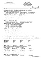
<span class='text_page_counter'>(1)</span>Water treatment 3.1 INTRODUCTION Water for public supply can be obtained from underground sources by wells sunk into aquifers, or from surface sources such as purpose-built reservoirs or lakes (collecting rainwater run-off or water from streams) and rivers. The safety of the water is of utmost concern – several million people die each year after consuming contaminated water. The primary aim in water treatment is the elimination of any pathogenic micro-organisms present. All the above-mentioned sources can be subject to pollution. In the case of underground water, polluted surface water can enter the saturation zone of an aquifer and so lead to its contamination. Pollution can come from waste tip leachate containing heavy metals and organic compounds, farm run-off containing nitrates and pesticides, and industrial wastes which may have been deliberately dumped down old coal mine shafts. River water can be affected by farm drainage, sewage works and industrial effluents, and also the run-off water from roads. Thus there is a need to maintain the quality of the aquatic environment to ensure that the water is suitable for treatment for public supply, and that the cost of treatment is kept as low as possible. In this unit we shall be looking at the treatment of water after it has been abstracted from a suitable source. While the prime function of water treatment is to produce a safe product, several stages are involved: 1. 2. 3. 4. 5.. the removal of suspended matter and rendering of the water clean, colourless and free from disagreeable taste and odour; the disinfection of the water so that the numbers of bacteria are reduced to an appropriate level; the removal of chemicals harmful to health and the reduction to low levels of chemicals that might otherwise interfere with normal domestic and industrial requirements; the reduction of the corrosive properties of the water and protection of the pipe supply system; the minimisation of the amount of material passing into the supply system which might encourage biological growth.. Raw water is usually abstracted from a river and pumped to a reservoir for storage and settlement. In the reservoir, the number of faecal bacteria is reduced through natural processes such as predation by protozoa and ultraviolet radiation from sunlight. Also, a large portion of the suspended solids settles out. The water is then conveyed from the reservoir to a treatment works. In some situations, particularly in hilly areas, rainwater is abstracted from a storage reservoir made by damming a valley in an upland catchment area, instead of from a river. In other instances, water may be drawn from aquifers. (These waters usually require little treatment due to their often unpolluted nature.) The basic treatment for river water is shown in Figure 19. It should be noted that not all the processes shown will be required for water from every source. The treatment used will depend on the quality of the abstracted water. For water that has little pollution, it may only be necessary to use preliminary settlement, rapid sand filtration and chlorination, whereas poor quality water may require even more treatment than that shown.. Figure 19 Diagram of a typical water treatment process.
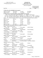
<span class='text_page_counter'>(2)</span> 3.2 PRELIMINARY TREATMENT The abstracted water is first screened to remove suspended and floating debris, such as leaves or branches, which could interfere with the operation of machinery in the treatment works. The water may then enter a preliminary settlement tank or storage reservoir. It then passes through screens again and goes to the treatment works. Screens may be classified by the size of their openings as coarse or fine, and may be in the forms of bars or continuous belts. Coarse screens are used primarily to protect the treatment works from physical damage, while the fine screens serve to remove material which might eventually block pipework in the system. Coarse screens usually consist of a series of metal bars spaced 5–15 cm apart. Fine screens, which follow the coarse screens, have a bar spacing of 5–20 mm. Screens are positioned in the inlet channel of the treatment plant at an angle of 60° to facilitate removal of the collected material or screenings by raking. The cleaning of the screens is important to prevent them choking. Bar screens can be raked by hand but are more usually cleaned by a mechanical raking operation, either on a time basis or by pressure-sensing probes which are activated by an excessive head loss (pressure drop) across the screen. A continuous chain scraper can also be used to clean bar screens (Figure 20). There are also fine mesh screens which are cleaned by water jets. These meshes can be on frames or, more commonly, in the form of a drum. A variation of the fine screen is the microstrainer (Figure 21). This consists of a rotating drum with a stainless steel micromesh fabric. The mesh size can range from 15 μm to 64 μm so that very fine suspended matter such as algae and plankton can be trapped. The trapped solids are dislodged from the fabric by high-pressure water jets using clean water, and carried away for disposal. Storage of the screened water in a preliminary settlement tank or reservoir smoothes out fluctuations in the water quality and helps to reduce the suspended solids content. It also reduces the number of pathogenic bacteria present, and the oxidation which can occur will allow the degradation of organic matter and the precipitation of soluble iron and manganese as oxides and hydroxides. It is generally recommended that storage should be for at least seven days in the case of river-derived supplies. The storage of water is particularly valuable when abstraction is not possible, e.g. during droughts, or when the water source is badly contaminated or in flood condition.. Figure 20 Continuous chain scraping system for a bar screen.
<span class='text_page_counter'>(3)</span> Figure 21 A typical microstrainer. After preliminary settlement, it may be necessary to aerate the water in the case of poor quality water with a low dissolved oxygen content. There are several ways in which this can be done but the simplest is to allow the water to fall over a series of steps so that it is able to entrain oxygen from the air. This is known as cascade aeration. In addition to increasing the oxygen content, aeration also helps to liberate soluble gases, such as carbon dioxide and hydrogen sulphide, and volatile organic compounds which could give an undesirable taste to the water. Aeration can reduce the corrosiveness of raw waters which are acidic due to their carbonic acid content. When the water is aerated, some of the dissolved carbon dioxide is displaced by the oxygen dissolving in the water. This causes some of the carbonic acid that has been formed in the water by the carbon dioxide to be converted back to carbon dioxide and water in order to maintain chemical equilibrium, as we discussed in Section 2.4. Aeration is also used to remove iron and manganese from solution. Iron and manganese can cause peculiar tastes and can stain clothing. Iron is soluble in water only in the absence of dissolved oxygen and at pH values below 6.5, when it is in the ferrous (Fe 2+) state. Aeration converts soluble iron into its insoluble hydroxide [Fe(OH)3] which can then be removed by filtration. Manganese can be removed in the same way. After aeration, the water may be passed through a further fine screen before entering the treatment works proper. 3.3 COAGULATION AND FLOCCULATION Coagulation is always considered along with flocculation and is used to remove particles which cannot be removed by sedimentation or filtration alone. These particles are usually less than 1 μm in size and are termed colloids. They have poor settling characteristics and are responsible for the colour and turbidity of water. They include clays, metal oxides, proteins, micro-organisms and organic substances such as those that give the brown coloration to water from ‘peaty’ catchment areas. The important property which they all have is that they carry a negative charge and this, along with the interaction between the colloidal particles and the water, prevents them from aggregating and settling in still water. The particles can be aggregated by adding either multivalent ions or colloids having an opposite (positive) charge. These are added as chemical coagulants. Chemicals commonly used as coagulants in water treatment are aluminium and ferric salts which are present as the ions Al3+ and Fe3+. These positively charged multivalent ions neutralise the naturally occurring negatively charged particles, thus allowing the particles to aggregate. At high concentrations of.
<span class='text_page_counter'>(4)</span> aluminium or ferric salts, and in the presence of sufficient alkalinity, insoluble hydroxides of aluminium or iron are formed (see below). In the precipitation reaction the colloidal particles are enmeshed within the precipitate and thus removed. The use of aluminium salts is not popular because of the (unproven) scare about Alzheimer's disease. The move away from aluminium salts was accelerated when aluminium sulphate was accidentally put into the treated water tank for the town of Camelford in 1988. Most plants now use ferric salts. If there is inadequate alkalinity in the water, it can be added in the form of lime (calcium hydroxide Ca(OH)2) or soda ash (sodium carbonate Na2CO3).. In some waters, even with the optimum dose of coagulant, coagulation is poor and so it is necessary to add extra substances known as coagulant aids. These aids can be clay, silica or polyelectrolytes. Polyelectrolytes (Figure 22) are long-chain organic molecules with chemical groups attached along the length of the chain, which becomes charged when the molecule is dissolved in water. The negative colloidal particles are attracted to positively charged chemical groups on the polyelectrolyte. As the coagulants are added, the water is mixed rapidly in a mixing chamber using a high-speed turbine. In small plants, coagulants are often added upstream of a weir in order to use the consequent turbulent motion to aid in mixing. Once coagulation has taken place, a very fine precipitate or floc will form. To aid this floc to coalesce with neighbouring particles and grow into larger flocs with more settleable masses, the water is gently stirred. The process of coalescence is known as flocculation. The gentle stirring can be achieved using paddles or baffles to induce a rolling motion in the water, and this continues for some 20–45 minutes. After this treatment, the water is passed for sedimentation.. Figure 22 Structure of typical polyelectrolytes.
<span class='text_page_counter'>(5)</span> 3.4 SEDIMENTATION When water has little or no movement, suspended solids sink to the bottom under the force of gravity and form a sediment. You will recall that we discussed a similar process in estuaries, with solids separating from the water. This process is called sedimentation. In water treatment it is used to remove solids from waters which are high in sediment content, and also to remove particles rendered settleable by coagulation and flocculation. The theory of sedimentation would seem to be quite simple. Earlier we had a widening river flowing more slowly, so if we make the settling tank large enough and the flow slow enough, this will enhance the rate of fall of the sediment towards the bottom of the tank. What other factors do you think need to be known? It will be necessary to know the density and the size of the particles to calculate their rate of fall. There should be no turbulence in the tank as it will tend to reduce settlement, and there must be an even flow through the tank to prevent a narrow stream flowing through quickly from one end to the other (i.e. channelling). Because of these factors we shall now look at settlement in greater detail. Sedimentation tanks can be of various types: rectangular with horizontal flow, circular with radial flow, or hopper-bottomed with upward flow (Figure 23). The circular and rectangular tanks are equipped with mechanical sludge-scraping devices to remove the wet sludge that has settled. In hopper-bottomed tanks, the sludge concentrates at the bottom of the hopper from where it can be drawn off. In radial and horizontal flow tanks any floating material is skimmed from the surface by a blade carried by the scraping mechanism, and is discharged to be combined with the settled sludge. In upward flow tanks, the main sludge removal is from the top of the sludge blanket (see Figure 23(c))..
<span class='text_page_counter'>(6)</span> Figure 23 Typical sedimentation tanks: (a) rectangular horizontal flow tank; (b) circular, radial-flow tank; (c) hopper-bottomed, upward flow tank. An idealised representation of a circular radial-flow tank is shown in Figure 24. There are four important zones in the tank: (a) Inlet zone – at the central well, which has a round baffle plate, the flow is established in a uniform radial direction so that short-circuiting does not take place..
<span class='text_page_counter'>(7)</span> (b) Settling zone – where settling is assumed to occur as the water flows towards the outlet. (c) Outlet zone – in which the flow converges up and over the decanting weirs. (d) Sludge zone – where settled material collects and is pumped out.. Figure 24 Radial-flow sedimentation tank. The performance of a settling tank is related to the settling velocity of the fine particles in suspension. The settling velocity is the speed at which the particles move downwards under gravity through the suspension, and for discrete particles this is dependent on the particle density and size. The retention time required by the particles to settle to the bottom of a settling tank is related to the settling velocity by the simple relationship. The time available for particles to settle out in the settling tank also depends on the flow rate of the suspension through the tank. This expression assumes that no short-circuiting takes place in the tank, i.e. that the water doesn't flow straight from inlet to outlet. Table 4 shows settling velocities for various types of suspended solids and the required retention times for sedimentation in a 3 m deep tank. Table 4 Settling velocities for different types of suspended solids and the retention time required in a 3 m deep tank for sedimentation to occur. Nature of solids. Settling velocity (mm Retention time for settling to occur in 3 m deep tank s−1) (hours). Clay, silt. 0.07. 11.9. Primary organic waste 0.42. 1.98. Aluminium and iron flocs. 0.83. 1.00. Activated sludge. 2.00. 0.42.
<span class='text_page_counter'>(8)</span> Grit. 20.00. 0.042. Notice that to achieve a separation of materials with low settling velocities, the retention time in the settling tank must be increased. In practice, this can be achieved by increasing the settling tank volume or decreasing the flow rate of suspension through the tank. Activity 100 m3 d−1 of a suspension of silt is passed through a settling tank with a 3 m deep settling zone. What is the effective settling zone area?. Self-assessment question A circular radial-flow tank has a settling zone depth of 4 m and a settling zone area of 700 m 2. What is the retention time necessary to remove organic detritus with settling velocities of 0.4 mm s −1 and greater? What flow rate is required through the tank?. In order to achieve the required retention time in the above SAQ, throughput of suspension must not be greater than 0.28 m3 s−1. But what if the same suspension was passed through a 2 m deep tank – half the depth? One might expect that in a shallow tank the same particles would reach the sludge zone at the bottom more quickly. Would this allow a larger throughput? Halving the tank depth would halve the retention time of particles in the tank; but would also halve the tank volume. So the flow rate through the shallower tank would be the same as for the deep tank. This independence of settling behaviour with depth has led to the development of shallow depth sedimentation tanks in which the flow is passed in parallel through a number of closely spaced inclined channels arranged in a device called a parallel plate separator (Figure 25). The slope of the settling channels is steep so that the tank is continuously selfcleaning (the solids slide off and go to the bottom of the tank). The advantage of such an arrangement is clear. For the same tank area, with n channels, throughput can be n-fold whilst retaining the same settling velocity in each channel..
<span class='text_page_counter'>(9)</span> Figure 25 A parallel plate separator within a sedimentation tank. The discussion so far has dealt with ‘ideal’ conditions in which particles settle under gravity without hindrance from other particles in the vicinity. An example of such a situation would be the settling of heavy grit particles or sand. There are, however, types of particles called flocculent particles which interact with other particles in their vicinity. An example would be organic suspended solids or the floc particles produced by chemical coagulation and flocculation of water, with a broad spectrum of sizes and surface characteristics. Different-sized particles settle at different rates so that larger particles will overtake or collide with smaller particles. These collisions may result in coalescence into larger aggregates with an increasing settling velocity so that the typical path of a flocculent particle is curved (Figure 26), indicating the increasing velocity with depth. One important requirement of settling tanks for treating flocculent suspensions is, therefore, that the depth should be great enough to provide the opportunity for particle agglomeration to occur. This is in contrast to the behaviour of discrete particles whose settling behaviour is independent of depth. The effect of tank depth on removal efficiency is shown in Figure 26. If the tank depth is reduced by half, the retention time is halved and the depth reached by each type of particle during that time is reduced. Nevertheless the discrete particle will again just reach the bottom of the reduced depth tank, whereas the flocculent particle will not have reached the tank floor and will be drawn off in the tank outflow. This is a simplification of what actually happens inside a sedimentation tank; however, it is generally considered that the overall effect of reducing settling tank depth is to reduce removal efficiency when treating flocculent particles.. Figure 26 Effect of tank depth on removal of discrete and flocculent particles.
<span class='text_page_counter'>(10)</span> Settlement tanks must therefore be designed deep enough to allow all particles to settle, and also to have flow such that settled solids are not disturbed and carried over the weir at the outlet of the settlement tank. A parameter known as the surface overflow rate or surface loading rate is used in the design of sedimentation tanks. This is defined as. Typical values for the surface loading rate range from 30 to 45 m 3 m−2 d−1. Activity What would the surface loading rate be for a rectangular sedimentation tank of surface area 10 × 30 m 2 with a maximum flow through rate of 8000 m3 per day?. Another important parameter in settlement tanks is the rate at which water flows over the weir, known as the weir overflow rate, expressed as. Typical values for the weir overflow rate range from 300 to 450 m 3 m−1 d−1. Activity What is the weir overflow rate for the tank in the previous exercise, the weir being on the shorter side of the tank?. This overflow rate exceeds the typical range of 300–450 m 3 m−1 d−1 and if used would tend to disturb the settled sludge. An acceptable value can be obtained by increasing the effective weir length. This can be achieved by increasing the breadth of the tank, but this would take up more land and be costly. An alternative and less costly solution would be to insert V-notches in the weir and so effectively increase the weir length, or have a suspended collection trough at the end of the tank so that the effluent could flow into the trough from either side, thus doubling the weir length. In our example the effective weir length could be doubled by using a trough and the overflow rate would be reduced to a more acceptable 400 m 3 m−1 d−1. Self-assessment question What length of effective weir would be required for a rectangular sedimentation tank with a maximum flow of 0.25 m3 per second if the weir overflow rate is to be 350 m 3 m−1 d−1?.
<span class='text_page_counter'>(11)</span> In the UK, upward-flow or hopper-bottomed sludge-blanket clarifiers (Figure 23c) are extremely popular. This type of tank is an inverted cone, with the flocculated water entering from the bottom of the cone. Because the cross-sectional area of the tank increases rapidly from the apex (at the bottom) to the base of the cone (at the top) the upward velocity of the water is reduced as it rises. In the tank there will, therefore, be a horizontal plane where the upward water velocity equals the average downward rate of fall of the floc. This results in the formation of a horizontal ‘blanket’ of floc suspended in the water. This blanket of floc acts as a filter through which the upward flowing water must pass. Maximum use of the tank is made when the top of the floc blanket is as high as possible in the tank. When the blanket becomes too dense, it is removed by bleeding off the excess floc. These days, due to cost reasons, upward flow tanks are often flat-bottomed with internal pipe work to distribute the flow across the full area of the tank base. Self-assessment question Which of the following characteristics of raw water are greatly improved by coagulation, flocculation and sedimentation? A Colour. B Taste. C Clarity. D Chloride concentration. E Nitrate concentration. 3.5 FLOTATION An alternative technique to that of sedimentation is flotation. This uses gas bubbles to increase the buoyancy of suspended solids. The gas bubbles attach to the particles and make their effective density lower than that of the water. This causes the particles to rise through the water to float to the top. Flotation may be achieved by several methods but the most effective form is dissolved air flotation. In this process (Figure 27) air is dissolved in water at elevated pressures and then released as tiny bubbles (30–120 μm) by reducing the pressure to atmospheric level. The principal advantages of flotation over sedimentation are that very small or light particles that settle slowly can be removed more completely and in a shorter time. Once the particles have reached the surface, they can be collected by a skimmer. Flotation does, however, require careful control to achieve high quality output..
<span class='text_page_counter'>(12)</span> Figure 27 Diagram of a dissolved air flotation system. 3.6 FILTRATION In filtration, the partially treated water is passed through a medium such as sand or anthracite, which acts as a ‘strainer’, retaining the fine organic and inorganic material and allowing clean water through. The action of filters is complex and in some types of filter biological action also takes place. Sand filters are used in water treatment to remove the fine particles which cannot be economically removed by sedimentation. They have been effective in removing Cryptosporidium, a protozoan parasite. Mechanical straining of the water is only a minor part of the filtration process, as the main process by which particles are retained is adsorption. In adsorption, the particles adhere to the filter material or previously adsorbed particles. If a particle passes close to a solid surface, there may be either electrical attraction or repulsion, depending on the surface charges of both the particle and the solid surface. Filtration in water treatment can be carried out using simple slow sand filters or, as is more usual for flocculated water, rapid gravity sand filters. A slow sand filter consists of a shallow basin in which about a metre of sand rests on a gravel base, underneath which there is a system of collection pipes and channels for the filtered water (Figure 28). The water to be treated flows down through the filter bed and, as it does so, a layer a few millimetres thick of algae, plankton and other microscopic plant life forms on the top. This layer is known as the Schmutzdecke, which is German for film or deck of dirt. In this layer, fine filtration takes place. In order to preserve this layer, the temperature and velocity of the inflow must be carefully controlled. Some biodegradation also takes place on the Schmutzdecke, resulting in a reduction of the organic matter, nitrate and phosphate which may be present in the water. The flow rate is normally in the range 0.1–0.2 m3 m−2 h−1. This means that a filter of, say, 21 m2 would produce a maximum of 0.2 × 21 = 4.2 m 3 of water per hour.. Figure 28 Section through a slow sand filter. When the rate of filtration begins to tail off after a month or two, the filter is drained and the top 2 cm of sand is removed to be replaced by fresh sand. Slow sand filters are expensive to build and operate, and require a large amount of space. They cannot be used for coagulated waters because of rapid clogging. Slow sand filters have been largely replaced by rapid gravity sand filters, which are particularly effective for water treated with coagulants and are less expensive than slow sand filters (Figure 29). The flow is much greater than in slow sand filters, being 4–8 m 3 m−2 h−1; hence a smaller filter (requiring a smaller space) will be adequate. Because of the high rate of flow, no Schmutzdecke is formed and hence little or no biodegradation takes place in these filters. The filter is cleaned at intervals of 24–48 hours by pumping water and air (to assist in scouring) under pressure backwards through the filter to wash out the trapped impurities. This process is called backwashing. Unlike slow sand filters which tend to produce water with a particularly low bacterial count, rapid filters produce water with high bacterial counts, increasing the necessity to follow them with disinfection before supplying the water to the public..
<span class='text_page_counter'>(13)</span> In many treatment plants where slow sand filtration is the key processing stage, rapid gravity filtration is employed prior to the slow sand filter in a process called double sand filtration. In this arrangement, the rapid gravity filters reduce the load of solid matter in the water before it goes to the slow sand filters. This allows a greater overall rate of treatment and the slow sand filters do not then need to be cleaned so often. A variation of the filtering process is the use of a layer of large anthracite grains (1.2–2.5 mm) on top of a layer of smaller (0.5–1.0 mm) sand grains, which are denser and have a smaller ‘intergrain’ pore size. Anthracite-sand filters tend to clog less rapidly because some of the floc adheres to the larger anthracite grains before the water filters through the sand. This means that increased filtration rates are possible without deterioration in filtrate quality.. Figure 29 Section through a rapid gravity sand filter. Self-assessment question List the advantages and disadvantages of slow sand filters and rapid gravity filters. 3.7 DISINFECTION Before water can be passed into the public supply, it is necessary to remove all potentially pathogenic micro-organisms. Since these micro-organisms are extremely small, it is not possible to guarantee their complete removal by sedimentation and filtration, so the water must be disinfected to ensure its quality. Disinfection is the inactivation of pathogenic organisms and is not to be confused with sterilisation, which is the destruction of all organisms. Worldwide, chlorine is the most popular disinfecting agent for drinking water, although the use of ozone has recently become more widespread. The use of chlorine in water treatment, while not being acceptable to all, does save lives. In Peru, the reduction of the chlorine dose led to a cholera outbreak in which thousands died. Chlorine acts as a strong oxidizing agent which can penetrate microbial cells, killing the micro-organisms. It kills most bacteria but not all viruses. It is relatively cheap and extremely soluble in water (up to 7000 g m−3). It has some disadvantages. If organics are present in the water being disinfected, it can lead to the formation of potentially carcinogenic disinfection by-products (e.g. trihalomethanes; see below). The World Health Organization has given health-based guidelines for a variety of disinfection by-products, such as chloroform. If the water has been previously treated by coagulation and flocculation, the chances of organic pollutants being present to form trihalomethanes are remote. Slow sand filters are effective in removing trace organics..
<span class='text_page_counter'>(14)</span> Chlorine is a dangerous chemical and so requires careful handling. It can also give rise to taste and odour problems: for example, in the presence of phenols it forms chlorophenols which have a strong medicinal odour and taste.. HOCl, hypochlorous acid, is the disinfecting agent and is referred to as free available chlorine. Since chlorine is an oxidizing agent, it reacts with all compounds in water which can be oxidized, e.g. converting nitrites to nitrates, and sulphides to sulphates. As mentioned above, it also reacts with any organics present and can form trihalomethanes (THMs). These are single carbon compounds with the general formula CHX3 where X may be any halogen atom (e.g. chlorine, bromine, fluorine, iodine, or a combination of these). Some THMs are known to be carcinogenic. There is evidence to link long-term low-level exposure and rectal, intestinal and bladder cancers. There is therefore a limit of 100 μg l −1 for total THMs in water supplied for potable use. Chlorine also reacts with ammonia to form chloramines. Thus when chlorine is added to water there is an immediate chlorine demand which must be satisfied before a residual of chlorine exists for disinfection. The formation of chloramines is as shown below:. The chloramines are disinfectants but not nearly as effective as free chlorine (they may have to be 25 times more concentrated to have the same effect). Chlorine in compounds such as chloramines is referred to as combined residual chlorine. Although not as effective as free chlorine in disinfection, combined chlorine is less likely to produce objectionable tastes and smells. One reason for this is that combined chlorine does not react with phenols, which may be present, to form chlorophenols. In fact, ammonia is sometimes added to water for this reason. Combined residuals also last longer than free chlorine. For disinfection with chlorine, the World Health Organization (WHO) guidelines recommend a minimum free chlorine concentration of 0.5 mg l −1 after a contact time of 30 minutes at a pH less than 8, provided that the turbidity is less than 1 NTU. The water leaving the chlorine contact tank is usually discharged with a chlorine concentration of 0.5–1.0 g m−3 to ensure that the water is kept safe throughout the supply and distribution system. Concern with hazards of chlorine storage has led to the adoption of electrolytic generation of chlorine on large water treatment plants. In this process, sodium hypochlorite solution with a chlorine content of 6– 9% is generated through the electrolysis of a solution of sodium chloride. Recently, ozone (O3, a blue gas and a very strong oxidizing agent) has become popular as a disinfectant, particularly as it is effective against viruses and spores. In the UK, it is often used to oxidize any pesticide residuals present. Also, ozonation does not produce toxic by-products such as trihalomethanes which can occur with chlorine. It can, however, form toxic bromates if bromine is present in the water. In France, there are about 600 water treatment plants using ozone as a disinfectant. The drawback with ozone, however, is that it is not possible to have a residual level, as there is for chlorine, to confer protection in the supply and distribution system (O3 rapidly breaks down to oxygen when any particles are present). In ultra-clean water, however, it will remain as O 3). Hence, after ozonation, the water is chlorinated before it goes into the supply system. The ozone used in water treatment plants is usually generated by passing dry air or oxygen between plates, across which a high voltage is imposed. It is expensive to produce, and the necessary equipment is complex. Ultraviolet radiation can also be used to disinfect water, but care must be taken to ensure that no suspended solids are present which could shield the micro-organisms and prevent them from being.
<span class='text_page_counter'>(15)</span> destroyed. UV systems are generally only used in small-scale water treatment units. They do not give a residual for protection in the distribution system. 3.7.1 Mixed oxidant gases system This is a relatively new system of disinfection. It involves electrolysis of high-purity NaCl brine to produce a mixture of chlorine dioxide, ozone and hypochlorite. This mixture is separated within the electrochemical cell by a membrane, or by exploiting density difference, and is then metered into the water requiring disinfection. The mixed oxidant gases are generated on demand and this is a great safety advantage, compared with having storage tanks of chlorine on site. The source for the disinfectant (highpurity NaC1) is relatively inexpensive and the mixed oxidants are more effective than chlorine alone in disinfection. Importantly, the mixed oxidant gases yield substantially lower levels of disinfection byproducts than chlorine gas or hypochlorites. The disadvantage of the mixed oxidant gases system (sometimes called MOGGOD – mixed oxidant gases generated on demand) is that it requires extensive skilled maintenance of the electrochemical and dosing systems. 3.7.2 Elimination of pathogens through solar disinfection The lack of safe drinking water in many developing countries has prompted research into simple methods of disinfecting small quantities of water. One such investigation at the University of Beirut in the Lebanon revealed that 99.9% of total bacteria in a water sample could be destroyed by 300 minutes exposure to direct sunlight. In effect this means that if you left a sample of water in a translucent container, a lot of the bacteria in it would be killed. Research to date has concentrated on transparent PET (polyethylene terephthalate) bottles, these being more robust than glass bottles and hence more practical for use in rural areas. It is important to first remove any particles in the water which may harbour or shield pathogens from the sunlight. Removal is effected by allowing any solids to settle out by sedimentation. It has been found that inactivation of pathogens is more effective if the water is fully oxygenated. The following is a procedure which works well: 1. Collect the raw water in a large jar and leave for about 12 hours, till the water appears clear. (Ideally, the turbidity should be reduced to below 30 NTU.) Pour the liquid above the residue (supernatant) through a piece of cotton cloth into a clean bucket. 2. Obtain a clear plastic bottle and clean it and its lid with some safe (boiled) water. Paint half of it black. (An alternative is to have a black surface, e.g. a black bin bag or a piece of tyre, on which to lay the bottle.) 3. Half fill the bottle with the clear water from (1) and put the lid on it. Shake the bottle vigorously for 30 seconds. This will ensure that oxygen from the headspace (the air space above the water) dissolves in the water. 4. Fill the remaining half of the bottle with the clear water from (1). 5. Lay the bottle on its side, and in such a position as to allow maximum sunlight to fall onto it. UV radiation from the sun reacts with the oxygen molecules in the water and, together with the heat from the sunlight, inactivates the pathogens. These pathogens in contaminated water sources are commonly viruses and bacteria, including Vibrio cholera. 6. Leave the bottle in the sun for at least five hours. If the weather is cloudy, leave outside for two days. 7. At the end of this period, the water should be safe for drinking. The graph below (Figure 30) shows the decay rate of faecal coliforms with exposure to sunlight. The UVA band (320–400 nm) of solar radiation is primarily responsible for the inactivation of the microorganisms..
<span class='text_page_counter'>(16)</span> Figure 30 Elimination of faecal coliforms with UV-A radiation. UV-A radiation intensity on a sunny day in the tropics is generally 10–20 W m −2, while total solar radiation might be 500–800 W m−2. Self-assessment question Why is it necessary to have a black surface in step (2) above? Self-assessment question List the advantages and disadvantages of chlorine and ozone as disinfecting agents. Self-assessment question Which of the following would be applicable to MOGGOD systems? A They are cheap and simple. B They use gases produced off-site. C The raw material is inexpensive. D Since chlorine is produced, the same problems arise with disinfection by-products as can happen with conventional water treatment. E None of the above.. 3.8 ADDITIONAL TREATMENT As a result of strict standards set by the EU Directive on the Quality of Drinking Water, it is now often necessary for drinking water to have further treatment to remove components such as nitrates and trace of organics. 3.8.1 Nitrate removal Nitrate in water has become a significant problem and the EU Directive sets a maximum admissible concentration of 50 g m−3 measured as NO3−. This is equivalent to 11.3 g m −3 as N. High nitrate levels can.
<span class='text_page_counter'>(17)</span> cause cyanosis or methaemoglobinaemia in babies. Legislation allows the designation of nitratevulnerable zones and these help to prevent nitrate levels in natural waters increasing in affected areas. Ion exchange is used in some treatment plants to remove nitrates from drinking water. In this process the water is passed through an ion exchange resin which removes the undesired ions and replaces them with ions which do not affect the water quality. This technology for nitrate removal was developed from water softening systems, which were used to remove the hardness-conferring ions Ca 2+ and Mg2+. At first, ion exchange was carried out with zeolites, which are naturally occurring insoluble sodium aluminosilicates. Zeolites were able to exchange sodium ions for other ions such as Ca 2+ and Mg2+. Artificial zeolites such as permutit are now produced. If the cation exchange sodium resin is represented by Na 2R, where R is the complex resin base, then the reaction for water softening is. The treated water then becomes richer in sodium and, unless the water was particularly hard, this is less of a problem. When all the sodium ions in the exchange resin have been replaced, the resin can be regenerated by passing a strong solution of sodium chloride through it:. For removal of nitrate ions, the exchange is with R*Cl where R* is another complex resin base:. The ion exchange vessels are taken out of service sequentially for regeneration using a brine solution which displaces the captured nitrate ions. The nitrate-rich brine product has to be disposed of. Recently, a process has been developed whereby this brine is electrolysed to convert the NO 3 to N2 gas, allowing reuse of the brine. As mentioned earlier, ion exchange is also used to reduce the hardness of a water (for example, the small units available for the home) by removing calcium and magnesium ions from water. It can also be used as a desalination system to reduce the salt content of a water. Small-scale ion-exchange units are commonly used in laboratories to produce pure water called deionized water, an alternative to distilled water. Deionized water requires the use of both cationic and anionic exchangers. Reverse osmosis (explained in the next paragraph) has become popular in removing pollutants such as trace organics and salts and it is worth considering for nitrate removal. When a solution of a salt is separated from pure water by a semi-permeable membrane that permits the passage of pure water but prevents that of the salt, water will tend to diffuse through the membrane into the salt solution, continuously diluting it. This phenomenon is called osmosis. If the salt solution is in an enclosed vessel, a pressure will be developed. This pressure in a particular solution is known as the osmotic pressure of that solution. Reverse osmosis is a process in which water is separated from dissolved salts in a solution by filtering through a semi-permeable membrane at a pressure greater than the osmotic pressure caused by the dissolved salts in the water. The pressure required increases in direct proportion to the concentration of salts. The salts could be in any form including nitrates. Removal rates in excess of 93% for nitrate have been reported for reverse osmosis systems. Operating costs and space requirements are said to be less than for equivalent ion exchange plants. The basic components of a reverse osmosis unit are the membrane, a membrane support structure, a containing vessel, and a high pressure pump. Cellulose acetate and nylon are the most commonly used membrane materials. The water to be treated is pumped at high pressure through the membrane module, and clean water is collected as permeate (Figure 31), with the unwanted material remaining in the retained liquid (retentate)..
<span class='text_page_counter'>(18)</span> Figure 31 A typical membrane filtration process. The concentration of retained material in the feed builds up with time, and the membrane can get clogged. To prevent this, periodic backwashing with either water or gas under pressure is undertaken. Continuous filtration with the feed flowing over the membrane surface is preferred over a batch process, as the flow promotes self-cleaning and enables longer runs between backwashing or replacement. To prevent clogging of the membrane, prior filtration of the feed water is necessary. To decrease scaling potential, iron and manganese removal may also be necessary. The pH of the feed should be adjusted to a range of 4.5–7.5 to inhibit scale formation. Figure 32 shows a schematic of a reverse osmosis system.. Figure 32 Schematic of a spiral-wound reverse osmosis module. Other options for nitrate removal include electrodialysis (Section 3.14.3) and biological denitrification. 3.8.2 Removal of trace organic compounds After conventional treatment, water may still contain trace concentrations of synthetic organic compounds, which, if left in the water, can lead to taste and odour problems. The problem is most likely to arise where the raw water source has been badly polluted. The problem can be solved by including the process of granular activated carbon adsorption after the filtration process. Activated carbon is carbon which has been activated by heating in the absence of oxygen. This results in the formation of many pores within each carbon particle. Charcoal is a form of activated carbon but with fewer pores. Granular.
<span class='text_page_counter'>(19)</span> activated carbon (GAC) can be obtained from roasting vegetable or animal matter at 800–900°C in a vacuum furnace. It can have a surface area of up to 1000 m 2 g−1. GAC is therefore an effective adsorbent of organic compounds. Its effectiveness can be measured by the reduction in the chemical oxygen demand (the oxygen needed to chemically oxidize all carbonaceous material present, COD) and the total organic carbon of the water. GAC can be used for the removal of soluble phenols which would produce strongly smelling and tasting chlorophenols upon reaction with chlorine in the disinfection stage. In the event that trihalomethanes are formed after disinfection by chlorine, GAC can be used to eliminate these toxic compounds. GAC, once exhausted, can be regenerated by heat treatment. Another method of removing trace organics is to oxidize them to harmless products such as CO 2 by using ozone. Ozone and activated carbon are capable of removing trace quantities of organics present in water. These substances are used for the reduction of pesticide levels in water supplies to comply with the limit specified by the European Union. Powdered activated carbon is also an option. It can be added to water for the adsorption of trace organics. It has been used to eliminate tastes and odours in drinking water brought about by algae, actinomycetes and fungi. It is usually added in the coagulation stage prior to sand filtration. Unlike GAC, the regeneration of powdered activated carbon is not practicable, so it is only used when intermittent water quality problems occur. Membrane filtration is becoming popular in water treatment and nanofiltration (see next section) has been employed for trace organics (pesticides) removal. Nanofiltration is similar to reverse osmosis, which you have already come across. Pesticides, which are often carcinogenic, are not at all desirable in potable water. The limit of each individual pesticide is 0.1 μg l −1, and for the sum of all the individual species, the limit is 0.5 μg l−1. The latter is still a very low concentration. It's the sort of concentration of sugar you'd get if you dissolved 1250 sugar cubes in Loch Ness! 3.9 MEMBRANE FILTRATION Membrane filtration is a process whereby particles smaller than about 10 −2 mm (which can pass through sand filters) are removed using synthetic polymeric membranes and a high pressure. The membrane effectively acts as a sieve. It is increasingly becoming popular as an advanced treatment process for water (especially for removal of Cryptosporidium) and wastewater (where water reuse takes place), and various possibilities are: microfiltration ultrafiltration reverse osmosis nanofiltration 3.9.1 Microfiltration This process removes particles between 0.05 and 5 μm in size. The water is pumped at a pressure of 100– 400 kPa through the membrane module. Microfiltration has been adopted by water companies as a means of removing some stages in the life cycle of the chlorine-resistant pathogens Cryptosporidium and Giardia. It is widely used to produce pure water for the electronics, pharmaceutical, chemical and food industries, by removing microbial cells and small particles. 3.9.2 Ultrafiltration (UF) This employs membranes with smaller pores (0.001–0.02 μm) than those for microfiltration and utilises much greater pressure (up to 3000 kPa). An atomic mass unit is 1/12 of the mass of a neutral atom of the most abundant isotope of carbon, i.e. I.66X 10−27 kg. Commonly, the membranes are made of polysulphone, polyacrylonitrile, polyamide and cellulose acetate. Inorganic ceramic membranes are also used. Owing to its ability to remove very small particles, UF is.
<span class='text_page_counter'>(20)</span> mainly used for the separation of macromolecules, allowing molecules with a mass of 1000 atomic mass units (amu) to pass through the membrane. UF is used as protection against Cryptosporidium by one water company in the south-east of England. It is also used in the removal of bacteria and viruses for food processing waters and for the removal of colour and humic substances from drinking water in small upland supplies. 3.9.3 Nanofiltration Nano is a prefix that means 10−9, i.e. very, very small. You may have come across nanotechnology. Nanofiltration is similar to reverse osmosis and employs membranes that are capable of physical sieving and diffusion-controlled transport. Nanofiltration systems operate at much lower pressures than reverse osmosis systems, but yield higher flow rates of permeate. The quality of the permeate is not as good as with reverse osmosis, with particles in the size range 0.0005–0.005 μm being removed. It is used for the removal of colour, humic acids, and trace organics such as pesticide residues, from drinking water. Self-assessment question Which of the following is true? A There are three important zones in a sedimentation tank, namely, the inlet zone, the settling zone and the outlet zone. B Flocculent particles in general will reach the base of a settlement tank ahead of discrete grit particles. C For a surface loading of 30 m 3 m−2 d−1, in a sedimentation tank with floor dimensions 14 m × 50 m, the maximum flow rate allowed is 2.4 m3 s−1. D It is the positive charge carried by colloidal particles and micro-organisms that prevents them from aggregating and settling. E An ion exchange resin to remove nitrate from water can be represented as NaR where R is the complex resin base. F Free available chlorine is a disinfection agent and is present in water as HOCl, hypochlorous acid. G Both granular and powdered activated carbon can be regenerated. 3.10 FLUORIDATION The addition of fluoride to water has caused much controversy and public debate. The problem seems to be that some see it as the addition of a poison, and others see it as the use of mass medication whether the individual wishes it or not. Many waters do, however, have a natural fluoride content (Figure 33) and it has been suggested that the presence of fluoride in a concentration of 1.0 mg l −1 is beneficial in preventing dental decay. Above this concentration there is the likelihood of ‘mottled teeth’ occurring. The EU Drinking Water Directive specifies a maximum value of 1.5 mg 1−1..
<span class='text_page_counter'>(21)</span> Figure 33 Natural and artificial fluoride concentrations in water supplies in England and Wales. Fluoride is added to the water as the last process in water treatment. There are three commonly used chemicals: . disodium hexafluorosilicate (Na2SiF6); sodium fluoride (NaF); hexafluorosilicic acid (H2SiF6).. In water, all these chemicals dissociate to give fluoride ions, e.g..
<span class='text_page_counter'>(22)</span> The three chemicals must be handled carefully during their addition to the water as they are harmful if they are inhaled, ingested or come into contact with the skin. It must, however, be remembered that the addition of chlorine to water is readily accepted and chlorine is a poisonous gas! Activity A natural water contains 0.55 mg l −1 of fluoride ion and is to be treated with sodium fluoride so that the final concentration will be 1.0 mg l −1 of fluoride ion. The flow of water to be treated is 1000 litres per second. Calculate the daily weight of sodium fluoride that will be required.. Self-assessment question 1000 kg of hexafluorosilicic acid (H2SiF6) is added per day to a flow of 15 000 l s −1 to achieve a concentration in the water of 1.0 mg l −1 fluoride ion. What was the original concentration of fluoride in the water?. As mentioned in Section 3.7, fluoride belongs to a group of chemicals called halogens. If compounds of bromine (another halogen) – called bromides – are present, and the water is treated with ozone (as might happen if pesticide residues are present), then there is a danger of bromates being formed. Bromates have been found to induce a high incidence of kidney tumours in male and female rats, and peritoneal mesotheliomas in male rats. Bromate is mutagenic in vitro and in vivo. There is therefore a limit of 10 mg l−1 imposed on levels of bromate in drinking water. 3.11 PLUMBO-SOLVENCY Many water supplies in the UK are naturally acidic, and when this type of water is supplied through lead pipes the lead dissolves into the water. Lead pipes are dominant in many older established areas. The Drinking Water Directive has set a maximum admissible concentration of 10 μg 1 −1 lead in water, to be achieved by the year 2013. The obvious solution to this problem is to remove all lead piping but this is a costly exercise. As an interim measure, the water leaving the treatment works can be dosed with lime or phosphate to increase the pH to 8.0–8.5 (making the water less acidic), thus reducing the extent to which the lead dissolves in the water. The solubility of lead is much reduced in hard water where the lead is.
<span class='text_page_counter'>(23)</span> precipitated as insoluble lead carbonate. Another practical measure (in the home) is to let the water run for a minute or two before using it. This is especially advisable in the morning when the lead concentration in the water may be high because the water has stood in the pipes overnight. 3.12 SLUDGE TREATMENT AND DISPOSAL The sludge collected in any sedimentation tank in the water treatment process has to be disposed of. In some instances the wet sludge is transported to the nearest sewage works where it is discharged into the raw sewage inlet channel. The presence of the added chemicals can help in the primary sedimentation of the crude sewage. Alternatively, the sludge can be sent to a landfill site after it has been concentrated into a cake by dewatering. The dewatering is carried out by pressure filtration, vacuum filtration or centrifugation. In pressure filtration, the sludge is pressed at high pressure between filter cloths. Vacuum filters are popular in the USA but few treatment works in the UK employ them. A slowly revolving drum, partly immersed in the sludge, carries a filter cloth through which water is sucked from the sludge under vacuum. In centrifuging, chemically or biologically conditioned sludge falls onto the centre of a rapidly rotating bowl. The solids are thrown to the outer edge of the bowl where they are removed by a scraper. With chemical-conditioned sludge, 80–98% of the solids can be separated this way. These solids would contain typically 10–35% water.. 3.13 GROUNDWATER TREATMENT The treatment of groundwater frequently does not extend beyond disinfection. However, groundwater may contain dissolved substances such as carbon dioxide and iron for which additional treatment (aeration, biological treatment, etc.) may be required. In some instances groundwater may be hard, and where the concentration of dissolved solids is greater than about 300 g m −3 it may be desirable to soften the water to reduce scale formation and soap wastage. The methods usually adopted for softening are precipitation or ion exchange. 3.14 DESALINATION In many parts of the world, surface water or non-saline groundwater stocks are not adequate to satisfy the water demand. While one may immediately think of the Middle East as being one such area, it is less obvious that many islands (e.g. the Canary Isles, Madeira, the Channel Islands) also suffer the same problem. In such circumstances, people have been forced to consider the sea and brackish underground aquifers as water sources. To make these saline waters potable, the salt has first to be removed by desalination. Desalination systems are also used on ships and on offshore oil and gas production platforms as a means of producing potable water. The two major desalination processes used worldwide are multistage flash distillation and reverse osmosis. Other techniques commonly used are electrodialysis and solar distillation, often for small communities. 3.14.1 Multistage flash distillation In this process (Figure 34) saline water (screened first, if it is sea water) is distilled under reduced pressure in a series of sealed tanks. Due to the reduced pressure, the water evaporates suddenly or ‘flashes’ at a temperature lower than 100°C, typically 80°C. Pure water condenses on cooling coils in the tanks and is collected. As the temperature of the feed water falls in each succeeding tank (as the latent heat of evaporation is extracted from it) a correspondingly lower pressure has to be maintained for flashing off to occur..
<span class='text_page_counter'>(24)</span> Figure 34 The multistage flash-distillation process. Brine at (A) passes under pressure in the condenser coils of the flash chambers to heat exchanger (B), and as it flows in the reverse direction, water vapour flashes off and is condensed on the cooler brine-filled coils above. The condensate forms part of the freshwater outflow at (C). The brine, now at 60°C, passes into flash chambers D and E, which contain condenser coils fed with raw sea water. This is recycled into the concentrated brine of the last flash chamber, and the resultant liquid is partly run off as waste and partly recycled to A.. Multistage flash (MSF) units are often located alongside power generation plants in order to utilise the waste heat generated in them. MSF plants can suffer from scale deposition and corrosion. Scale deposits of, for example, CaCO3 and Mg(OH)2 can interfere with the transfer of heat between different parts of the process, and can increase the resistance to fluid flow due to an increase of surface friction. Scale deposition is usually prevented by the addition of scale inhibitors to the feed. These modify the crystal structure of the scale and prevent it building upon surfaces. Sulphate-reducing bacteria, often present in sea water, can contribute to corrosion. Under anaerobic conditions these bacteria reduce sulphate ions to hydrogen sulphide, which in turn dissolves away iron, forming iron sulphide. This results in ‘pitting’ corrosion. Other bacterial species can oxidize the H 2S to sulphuric acid, which is very corrosive. Control of all forms of bacterially induced corrosion consists essentially of either eliminating conditions suitable for their growth, or, if this is not practicable, using biocides to prevent them colonising the parts at risk. 3.14.2 Reverse osmosis This technique, explained in Section 3.8.1, is rapidly becoming a major means of desalination, with research producing membranes with lower operating pressures (and hence lower operating costs). Originally a pressure of 14 × 106 Pa was needed to separate pure water from sea water but with newer membranes only half this pressure is required. Reverse osmosis membranes operate at ambient temperature, in contrast to multistage flash distillation, and this lower temperature minimises scaling and corrosion problems. To prevent problems with organic fouling of the membrane, pretreatment of the feed water is required. 3.14.3 Electrodialysis Electrodialysis is an electrochemical process in which ion transfer separates salt from water. It is effective only for substances that can be ionized: for example, salt (NaCl) becomes, in solution, a mixture of Na + and Cl− ions. (Silica, on the other hand, does not ionize and hence is not removed by electrodialysis. It could, however, be removed by reverse osmosis.) When electrodes, connected to a suitable direct current supply, are immersed in a salt solution, current will flow, carried by the ions. The ions with a positive charge are attracted towards the negative cathode and are called cations. Negatively charged anions flow towards the positive anode. In electrodialysis, filters or membranes selectively impervious to cations or anions are placed alternately between the electrodes (Figure 35). Cation filters permit the flow of anions but act as a barrier to positively charged cations. Conversely, anions are held back by the anion filter while cations pass through. In certain compartments of the tank, ions will collect as their flow is checked by an appropriate filter. Cells of increasing salt concentration thus alternate with cells of salt depletion. Water that is sufficiently desalinated is extracted from the appropriate compartments. Electrodialysis is.
<span class='text_page_counter'>(25)</span> only generally used with brackish waters as it is uneconomic for sea water desalination. It is used together with ion exchange and activated carbon to produce ultra-pure water for the electronics and pharmaceutical industries.. Figure 35 The principle of electrodialysis. 3.14.4 Solar distillation The energy available in solar radiation can be harnessed to distil sea water. In a simple and inexpensive solar still system designed by the Technical University of Athens, for the island of Patmos, sea water is first pumped to a feed reservoir from which it flows by gravity, when required, into a large shallow basin divided into long narrow sections (Figure 36). Separating these channels are concrete strips, which provide access for maintenance. The interior surface of the entire basin is lined with butyl rubber sheet. Above each water-filled section is a double sloping glass roof supported by a light aluminium structure. Heat from the sun passes through the glass, causing evaporation from the sea water surface. The vapour condenses on the inside of the glass and runs down to channels at the edges of the sealed unit along which it travels to the freshwater storage reservoir. The salt concentration in the basin sections grows steadily stronger, and once every two days the resulting brine is run off to the sea, being then replaced by more sea water. Experience has shown that the 48-hour cycle avoids the formation of scale. As the sun does not shine every day, the designers have incorporated a second water channel in the concrete strips. These are fed from the upper surface of the glass panels, and from the concrete itself, when it rains..
<span class='text_page_counter'>(26)</span> Figure 36 Principle of a solar still. The output of distilled water from the Patmos solar still averages three litres per square metre of water surface per day. The only running costs of the system are those for pumping sea water to the feed reservoir, and for general maintenance, which includes cleaning the glass panels. If you have tried to drink distilled water you will know that water without any salts is insipid. It is also corrosive, due to the deficiency of ions which would be present if the water were in its natural state. Lime (Ca(OH)2), phosphates and bicarbonates are added to raise the alkalinity and make the water less corrosive. These chemicals also raise the level of total dissolved solids (TDS) to about 300 mg l −1, to give the water taste. If unpolluted brackish groundwater is available, this can be used instead to raise the TDS level. Often a combination of the two – addition of chemical salts and blending with underground water – is economic. Such a procedure is used in the water supply of Muscat in the Sultanate of Oman. After adjustment of TDS content, the pH is corrected if necessary. Finally, the water is disinfected and passed into transmission mains to feed service reservoirs (see Section 4)..
<span class='text_page_counter'>(27)</span> 3.15 SUMMARY The basic water treatment process for surface waters consists of preliminary screening and storage, followed by coagulation and flocculation to allow the aggregation of colloidal particles. Sedimentation of the aggregated particles produces sludge and partially purified water. The purification process is completed by filtering and disinfecting the water before distribution. Some waters may require additional treatment: for example, nitrate removal, or fluoridation, or further removal of organic material by granular or powdered activated carbon. The pH may have to be adjusted to minimise plumbo-solvency in areas served with lead distribution pipes. The sludge produced in water treatment can be sent to a sewage works where it can aid primary sedimentation, or it can be dewatered and buried at a landfill site. Small quantities of water can be disinfected by solar radiation and this is useful in remote locations. In areas of the world lacking adequate quantities of surface water or non-saline groundwater, desalination is practised, with the major processes being multistage flash distillation and reverse osmosis. Self-assessment question List the four commonly used desalination processes for the production of potable water..
<span class='text_page_counter'>(28)</span>