Tài liệu Configuring BGP ppt
Bạn đang xem bản rút gọn của tài liệu. Xem và tải ngay bản đầy đủ của tài liệu tại đây (26.48 KB, 4 trang )
1 - 4 Semester 5: Advanced Routing v2.0 - Lab 8.8.1 Copyright 2001, Cisco Systems, Inc.
8.8.1 Configuring BGP
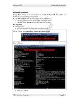
Lo0 192.168.0.2/24
Lo1 192.168.1.3/24
S0/1 172.16.0.2/30S0/0 10.0.0.2/30
S0/0 172.16.0.1/30S0/0 10.0.0.1/30
Lo0 12.0.1.1/24
Lo0 172.16.1.1/24
AS 200 AS 300
AS 100
SanJose3
ISP1A
ISP2
Objective
In this lab, you configure BGP to exchange routing information with the two Internet
service providers (ISPs).
Scenario
The International Travel Agency relies extensively on the Internet for sales. The company
has contracted with two separate service providers for fault-tolerant Internet connectivity.
You must configure BGP to run between the company’s SanJose3 boundary router and
the two ISP routers.
Step 1
Build and configure the network according to the diagram, but do not configure a routing
protocol. Configure a loopback interface with an IP address for each ISP router, as
shown. These loopbacks simulate real networks that can be reached through the ISP.
Configure two loopback interfaces with the IP addresses for the SanJose3 router. These
loopbacks simulate the connections between the core routers.
Use ping to test connectivity between the directly connected routers.
Note: The ISP1A router will not be able to reach the ISP2 router.
2 - 4 Semester 5: Advanced Routing v2.0 - Lab 8.8.1 Copyright 2001, Cisco Systems, Inc.
Step 2
Configure the ISP routers. In this lab, you must configure the providers’ equipment as
well as the International Travel Agency’s boundary router, SanJose3. On the ISP1A
router, enter the following configuration:
ISP1A(config)#router bgp 200
ISP1A(config-router)#neighbor 10.0.0.2 remote-as 100
ISP1A(config-router)#network 12.0.1.0 mask 255.255.255.0
On ISP2’s router, configure BGP (as shown here):
ISP2(config)#router bgp 300
ISP2(config-router)#neighbor 172.16.0.2 remote-as 100
ISP2(config-router)#network 172.16.1.0 mask 255.255.255.0
With the ISP routers configured, you can now set up the International Travel Agency’s
boundary router, SanJose3.
Step 3
Configure the SanJose3 router to run BGP with both providers. Use the following
configuration:
SanJose3(config)#router bgp 100
SanJose3(config-router)#neighbor 10.0.0.1 remote-as 200
SanJose3(config-router)#neighbor 172.16.0.1 remote-as 300
SanJose3(config-router)#network 192.168.0.0
SanJose3(config-router)#network 192.168.1.0
This completes the BGP configuration. Check SanJose3’s routing table with the show
ip route command:
SanJose3#show ip route
Gateway of last resort is not set
172.16.0.0/16 is variably subnetted, 2 subnets, 2 masks
B 172.16.0.0/16 [20/0] via 172.16.0.1, 00:01:24
C 172.16.0.0/30 is directly connected, Serial0
10.0.0.0/8 is variably subnetted, 2 subnets, 2 masks
B 10.0.0.0/8 [20/0] via 10.0.0.1, 00:01:47
C 10.0.0.0/30 is directly connected, Serial1
C 192.168.0.0/24 is directly connected, Loopback0
C 192.168.1.0/24 is directly connected, Loopback1
SanJose3 has routes to the loopback networks at each ISP router. Verify that SanJose3
has connectivity to these networks by pinging each loopback address from SanJose3’s
console. These pings should be successful.
3 - 4 Semester 5: Advanced Routing v2.0 - Lab 8.8.1 Copyright 2001, Cisco Systems, Inc.
Step 4
Use show commands to verify SanJose3’s operation. On SanJose3, issue the show ip
bgp command:
SanJose3#show ip bgp
BGP table version is 5, local router ID is 192.168.1.3
Status codes: s suppressed, d damped, h history, * valid,>best,
I-internal
Origin codes: i - IGP, e - EGP, ? - incomplete
Network Next Hop Metric LocPrf Weight Path
*> 10.0.0.0 10.0.0.1 0 0 200 i
*> 172.16.0.0 172.16.0.1 0 0 300 i
*> 192.168.0.0 0.0.0.0 0 32768 i
*> 192.168.1.0 0.0.0.0 0 32768 I
1. What do the asterisks (*) next to each route indicate?
2. What do the > symbols next to each route indicate?
3. What is the local router ID?
4. Which table version is displayed?
On the ISP1A router, issue the shutdown command on Loopback0. Return to SanJose3
and issue the show ip bgp command again.
5. Which table version is displayed?
The version number will vary, but the shutdown command would have caused a routing
update, so the version should be one higher than the last.
Bring the ISP1A router Loopback0 back up by issuing the no shutdown command.
On SanJose3, issue the show ip bgp neighbors command. Here is a partial sample
output:
BGP neighbor is 172.16.0.1, remote AS 300, external link
Index 2, Offset 0, Mask 0x4
BGP version 4, remote router ID 172.16.1.1
BGP state = Established, table version = 5, up for 00:02:24
Last read 00:00:24, hold time is 180
4 - 4 Semester 5: Advanced Routing v2.0 - Lab 8.8.1 Copyright 2001, Cisco Systems, Inc.
6. Based on the output of this command, what is the BGP state between this router and
ISP2?
7. How long has this connection been up?
Step 5
Check ISP2’s routing table with the show ip route command. ISP2 should have a
route that belongs to ISP1A (12.0.1.0).
If SanJose3 advertises a route belonging to ISP1A, and ISP2 installs that route in its
table, ISP2 might then attempt to route transit traffic via the International Travel Agency.
You need to configure the SanJose3 router so that it advertises only International Travel
Agency networks (192.168.0.0 and 192.168.1.0) to both providers. On the SanJose3
router, configure the following access list:
SanJose3(config)#access-list 1 permit 192.168.0.0 0.0.255.255
Then apply this access list as a route filter using the distribute-list keyword with
the BGP neighbor statement:
SanJose3(config)#router bgp 100
SanJose3(config-router)#neighbor 10.0.0.1 distribute-list 1 out
SanJose3(config-router)#neighbor 172.16.0.1 distribute-list 1 out
After you configure the route filter, check ISP2’s routing table again. The route to 12.0.1.0
(ISP1) should still be in the table.
Return to SanJose3 and issue the clear ip bgp * command. You have to wait until
the routers reach the Established state, which might take several seconds.
After the routers reach the Established state, check ISP2’s routing table again. The route
to 12.0.1.0 (ISP1) should no longer be in the routing table.
The route to 172.16.1.0 (ISP2) should not be in ISP1A’s routing table.