Research on field weakening based on reactive power with BLDC motor for electric vehicle application
Bạn đang xem bản rút gọn của tài liệu. Xem và tải ngay bản đầy đủ của tài liệu tại đây (198.98 KB, 5 trang )
Research on Field-Weakening Based on Reactive Power with
BLDC Motor for Electric Vehicle Application
∗
Jinsong Kang
Department of Electrical Engineering,
TongJi University,Shanghai,P.R.C.,
Email:
Department of Electrical and Computer Engineering,
Ryerson University,Toronto,Canada
Guoqing Xu
Department of Electrical Engineering,
TongJi University,Shanghai, P.R.C.
Email:
Shenzhen Institute of Advanced Technology
ShenzhenP.R.C.
Bo Hu
Department of Electrical Engineering,
TongJi University, Shanghai, P.R.C.
Email:bobo
Zhouyun Zhang and Jun Gong
Ananda Drive Technology Corporation,
Shanghai, P.R.C.
Email:{zzy & gjun}@ananda.com.cn
Abstract— Brushless Direct Current (BLDC) motor with the
high power density and the high efficiency characteristic is been
used to Electric Vehicle. The mathematical model of BLDC
motor under rotor flux linkage direction reference frame was
given. The chart of field-weakening vector control and basic
principle of field-weakening control strategy were analyzed.
The theory of field-weakening based on reactive power with
BLDC motor was proposed. The drive system of field-weakening
based on reactive power using BLDC motor was designed.
The experiment and result was test the validity of field-
weakening based on reactive power with BLDC for Electric
Vehicle Application.
Index Terms— BLDC motor; Electric vehicle; field-
weakening; reactive power;
I. INTRODUCTION
The electric vehicle(EV) is the cleanenergy saving and
environmental protection transportation vehicle, which hav-
ing no pollution, low heat radiation , the noise small, not
consumed the gasoline in the travel process. It applying many
kinds of energy, is called ”star of the tomorrow”. The drive
system is one power core of the electric vehicle, realizing the
vehicles power performance. Along with the new material
technology, the computer technology, the power electronics
technology and the microelectronic technology rapid de-
velopment, the electric vehicle mostly uses the alternating
current (AC) machine. It is the motive research hot spot that It
is the motive research hot spot that Brushless Direct Current
(BLDC) motor with the high power density and the high
efficiency characteristic is been used to EV. The motor has
inherit the predominant timing performance of the traditional
motor, as well the less volume, lighter weight, high efficiency
less moment of inertia and without exciting wastage, and also
discard the commutator and brush. Therefore it’s widely used
∗
and has good prospect[1]-[3].
At present, research on field-weakening of BLDC motor all
obtains the best electric current vector to control the inverter
to obtain certain effect under the different rotational speed ,
in the foundation of not modifying the electrical machinery
structure, resting on these characteristic curve such as the
biggest torque/current path, the electric current and the volt-
age limit ellipse .Vector control technology is not suitable
for weak magnetic control of BLDC motor with trapezoidal
wave permanent magnetism, because not realizing electrical
machinery complete decoupling[4]-[6]. This article proposes
transient powerless torque theory from the basic electric and
magnet correlation, the theory is brought forward to meet
the phase advancing control method. Without complicated
vector transform, the method calculated current instruction
and angle instruction based on the given torque and motor
speed feedback, and achieves high control precision in the
high speed field-weaken area.
II. B
ASIC PRINCIPLE OF FIELD
-
WEAKENING CONTROL
STRATEGY WITH
BLDC
MOTOR
The permanent magnet is produced the constant excitation
magnetic field when not considering the temperature influ-
ence of rotor permanent magnet. It is only can carry on
the equivalent field-weakening through the stator magnetic
field to the air gap magnetic field. Basic principle of field-
weakening control strategy with BLDC motor all is uses
the armature reactions of the stator current. Through the
stator magnetic potential and the rotor magnetic potential
composing, causing the air gap magnetic potential to reduce,
the induced potential of stator winding reduces. When ne-
glecting the saturation effect of stator inductance parameter
1-4244-1092-4/07/$25.00 © 2007IEEE.
437
Proceedings of the 2007 IEEE
International Conference on Integration Technology
March 20 - 24, 2007, Shenzhen, China
of BLDC motor, it’s mathematical model under rotor flux
linkage direction reference frame is like as the formula 1.
u
d
= R
1
i
d
+ pψ
d
− ω
e
ψ
q
u
q
= R
1
i
q
+ pψ
q
+ ω
e
ψ
d
ψ
d
= L
d
i
d
+ ψ
m
ψ
q
= L
q
i
q
(1)
In the formula, u
d
and u
q
represent direct axis compo-
nent and quadrature axis component of the stator voltage
respectively (V), i
d
and i
q
represent direct axis component
and quadrature axis component of the stator current respec-
tively (A); ψ
d
and ψ
q
represent direct axis component and
quadrature axis component of the stator flux linkage (Wb);
ω
q
represents the synchronization angular speed (rad/s)L
d
and L
q
represent direct axis component and quadrature axis
component of the stator inductance (H); ψ
m
represents rotor
permanent flux linkage (Wb) [7].
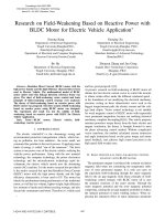
The space vector chart of BLDC motor is shown as Figure 2
through stator voltage, stator current and stator flux linkage
respective expressed by space vector form. The vector control
of DLDC motor is advance control to the stator current
under the rotor flux linkage direction frame. Field-weakening
control is achieved by reducing gap flux linkage , through i
d
direct axis component the stator current multiplying L
d
(the
direct axis inductance) counteract permanent flux linkage.
d
q
A
→
m
ψ
→
s
ψ
→
s
I
d
i
q
i
ϕ
θ
β
iL
dd
iL
Fig. 1. Chart of field-weakening vector control of BLDC motor.
In figure 1, ϕ is the angle between stator current vector
and permanent magnetism rotor q’s axis, is called the inter-
nal power factor angle; β is the angle between permanent
magnetism rotor flux linkage and the stator flux linkage,
calling the power factor angle; θ is the phase angle between
rotor d axis and A phase winding middle line in the stator
winding reference. The influence of stator armature reaction
on rotor magnetic field increases magnetism after degausses
first when the angle maintains at 90◦ about between the stator
magnetic field and the rotor magnetic field of BLDC motor,
causing each magnetic flux mean value maintenance to be
extremely invariable, namely only changing its peak-to-peak
value not to change its phase. Equivalent field weakening
can be achieved when the demagnetization function of stator
current armature reaction is bigger than the increasing action
through phase change ahead of time. Field-weakening and
speed increasing is achieved by equivalent weakening the
winding magnetic flux through the stator current armature
reaction. When BLDC motor using PWM control, the stator
winding is at unceasingly the power on and off condition
periodically, the air gap magnetic flux is weakened along
with the rotor position changing[8].
III. T
HE THEORY OF FIELD
-
WEAKENING BASED ON
REACTIVE POWER WITH
BLDC
MOTOR
The electrical machinery power is composed by the active
power and the reactive power[9]-[10]. In the static α − β
frame, the active power P
e
and reactive power Q
e
of BLDC
motor which with the stator winding opposite electromotive
is respectively shown as formula 2,3:
P
e
=
→
u
1
·
→
i
1
≈
→
e
1
·
→
i
1
= |e
1
|·|i
1
| cos ϕ = |e
1
|·|i
1
| cos (β − α)
= |e
1
|·|i
1
| (cos β cos α +sinβ sin α)=e
α
· i
α
+ e
β
· i
β
(2)
Q
e
=
→
u
1
×
→
i
1
≈
→
e
1
×
→
i
1
= |e
1
|·|i
1
| sin ϕ = |e
1
|·|i
1
| sin (β − α)
= |e
1
|·|i
1
| (sin β cos α − cos β sin α)=e
β
· i
α
− e
α
· i
β
(3)
In the above formula, the electromagnetism torque com-
ponent T
e
and reactive power torque component S
e
can be
obtained by formula 4,5.
T
e
=
P
e
ω
1
=
e
α
· i
α
+ e
β
· i
β
ω
1
(4)
S
e
=
Q
e
ω
1
=
e
α
· i
β
− e
α
· i
β
ω
1
(5)
The electromagnetism torque component T
e
and reactive
power torque component S
e
are scalars, not through the com-
plex vector transformation. T
e
and S
e
under different angle
are calculated through simple 3/2 mathematics operation of
three-phase counter-electromotive force and the three-phase
current under the certain speed. Torque control command T
e
can directly obtained in operating mode of vehicle. If the
relation between i
α
and i
β
can be obtained through current
control strategy, reactive power torque component S
e
can
be calculated. The magnetic torque of BLDC motor is fully
obtained by the phase advance control in low speed area and
field-weakening control with permanent over speed area. The
principle of stator control based on reactive power theory for
BLDC motor is described by formula 5.
i
α
i
β
=
1
f
2
α
(θ)+f
2
β
(θ)
f
α
(θ) f
β
(θ)
−f
β
(θ) f
α
(θ)
·
T
e
S
e
(6)
438
Fig. 2. Chart of field-weakening vector control of BLDC motor.
The instantaneous value of three-phase electric current is
obtained by the counter-Clark transformation according to the
above equation. Field weakening control based on reactive
power with BLDC motor includes operating mode of biggest
torque/Current ratio control in low speed and operating mode
of weak magnetic control with permanent power in high
speed. The operating mode using weak magnetic control
in low speed is for fully using permanent magnetism mag-
netic resistance torque, enhancing electrical machinery the
torque/Current ratio; The operating mode using the weak
magnetic control in high speed is in order to use the stator
current the straight axis component to realize the air gap
magnetic flux equivalent weak magnetism, realizing weak
magnetic control keeping permanent power.
IV. T
HE DRIVE SYSTEM OF FIELD
-
WEAKENING BASED ON
REACTIVE POWER USING
BLDC
MOTOR
The principle of field-weakening based on reactive power
is realized by electrical current phase advance according
to the current torque instruction and the current rotational
speed. The angle ahead of time can be obtained by the angle
of the stator current opposite the counter electromotive force,
which are calculated by the d-axis component and q-axis
component of stator current based on reactive power theory.
The stator current peak value serves as the electric current
instruction value of the stator current with closed-loop
control. The control block diagram of field-weakening based
on reactive power theory using square-wave electric current
control BLDC motor is shown as figure 2
In the chart, torque instructions is accepted by
communication control unit through the CAN from
vehicle controller. The reactive power torque is calculated
by the control command and the speed .The electric current
function table and the field-weakening control angle function
table are calculated by torque instruction signal and speed
signal. The PWM duty factor signal is to come from the
electric current function table and field-weakening control
angle function table. The signal is also comes form the DC
voltage signal, the phase current signal, the temperature
signal, real-time trouble protect signal of drive system.
439
V. T
HE EXPERIMENT AND RESULT OF FIELD
-
WEAKENING
CONTROL WITH
BLDC
MOTOR FOR ELECTRIC VEHICLE
In order to test the validity of field-weakening control
based on reactive power with BLDC motor. The experiments
are carried out in an AC drive system, which parameters
of the square-wave electric current control BLDC motor are
list as: rated power is 65kW, maximum speed is 11000 rpm,
maximum torque is 125Nm. The three-dimensional chart of
stator electric current instruction calculated on reactive power
theory is shown as 3. The three-dimensional chart of angle
instruction obtained from field-weakening based on reactive
power theory is shown as 4
The rotor position signal, the corresponding PWM profiles
and the electric current profiles according to field-weakening
control based on above instructions under different speed
experiment are respectively shown as 5 and 6
Fig. 3. Three-dimensional chart of stator electric current instruction
VI. CONCLUSION
It is availability to field-weakening control based on re-
active power theory. When the BLDC motor is in the low
speed with permanent torque control operating mode, Under
the same speed and same peak value torque, experimental
result is shown to obtain 5 percent higher torque under the
same electric current, more to enhance the drive system
controllability and control precision. When in high speed
operating mode, the stator current peak can be reduced 15 ∼
20 percent under same torque in the field-weakening control
region, thus the system reliability and the power module
security enhance greatly.
VII. ACKNOWLEDGMENTS
The authors would like to thank Dept. of Electric Engineer-
ing, Tongji University and Ananda Drive Technology Corpo-
ration for their helpful support and constant encouragement.
Fig. 4. Three-dimensional chart of angle instruction obtained from field-
weakening
Fig. 5. Experiment waveforms around 1000 rpm with field-weakening
control
Fig. 6. Experiment waveforms around 10000 rpm with field-weakening
control
R
EFERENCES
[1] G.Henneberger, et al. Comparison of Three Different Motor Types for
Electric Vehicle Application. Proc. of the 12th International Electric
440
Vehicle Symposium, Anaheim California. 1994:615-624
[2] Masahiko Tahara, et al. Performance of Electric Vehicle. Proc. of the
21th International Electric Vehicle symposium, Anaheim California.
1994:89-96.
[3] H. Yamamuro, et al. Development of Powertrain System for Nissan
FEV. Proc. of the 11” International Electric Vehicle Symposium,
Florence. 1992, No.13.03.
[4] Miti, G.K., and Renfrew, A.C.: ”Computation of constant current field-
weakening performance profiles in brushless DC motors”. Proceedings
of 8th international conference on Power electronics and motion
control, Prague, Czech Republic, September IEE Proc. Electron. Power
Appl., Vol. 148, No. 3, May 2001 271-273
[5] Lei Hao, et al, BLDC Motor Full Speed Range Operation Including the
Flux-Weakening Region, IEEE, Trans. Industry Applications, vol23,
no.4, pp618 624, 2003
[6] Thomas M.Jahns, ”Flux-Weakening Regime Operation of an Interior
Permanent-Magnet Synchronous Motor Drive”,IEEE, Trans. Industry
Applications, vol23, no.4, pp.681-689, July/August 1987
[7] F.Bodin, New reference frame for brushless DC motor drive, in Proc
IEE Power Electronics and Variable Speed Drives, pp.554-559, Sep.
1998.
[8] Shigeo Morimoto, et al.Effects and Compensation of Magnetic Satu-
ration in Flux-Weakening Controlled Permanent Magnet Synchronous
Motor Drives”, IEEE, Trans. Industry Applications, voL30, no.6,
pp.1632-1637, 1994
[9] H. Zeroug, et al. Dahnoun, Performance Prediction and Field Weak-
ening Simulation of a Brushless DC Motor, Power Electronics and
Variable Speed Drives, 18-19 September 2000, Conference Publication
No. 47 pp. 231-237, IEE 2000
[10] GK. Miti, et al. Field-weakening regime for brushless DC motors based
on instantaneous power theory, IEE Proc-Electn Power Appl, vol.148,
no.3, pp.265-271, May 2001
441