Chẩn đoán vết nứt trong cần trục tháp bằng phương pháp thử nghiệm động TA
Bạn đang xem bản rút gọn của tài liệu. Xem và tải ngay bản đầy đủ của tài liệu tại đây (4.91 MB, 122 trang )
MINISTRY OF EDUCATION AND
TRAINING
VIETNAM ACADEMY OF
SCIENCE AND TECHNOLOGY
GRADUATE UNIVERSITY OF SCIENCE AND TECHNOLOGY
-----------------------------
LÊ TUẤN ANH
STUDY ON PARAMETRIZATION OF PHOTOFISSION
CROSS-SECTION OF 238U AND OPTIMIZATION
SIMULATION USING GEANT4 FOR DESIGN OF THE
IGISOL FACILITY AT ELI-NP PROJECT
PhD THESIS IN ATOMIC AND NUCLEAR PHYSICS
Hanoi – 2021
MINISTRY OF EDUCATION AND
TRAINING
VIETNAM ACADEMY OF
SCIENCE AND TECHNOLOGY
GRADUATE UNIVERSITY OF SCIENCE AND TECHNOLOGY
-----------------------------
LÊ TUẤN ANH
STUDY ON PARAMETRIZATION OF PHOTOFISSION
CROSS-SECTION OF 238U AND OPTIMIZATION
SIMULATION USING GEANT4 FOR DESIGN OF THE
IGISOL FACILITY AT ELI-NP PROJECT
Major: Atomic and Nuclear physics
Code: 9440106
PhD THESIS IN ATOMIC AND NUCLEAR PHYSICS
SUPERVISORS:
1. Dr, PHAN VIET CUONG
2. Prof, DIMITER L. BALABANSKI
Hanoi – 2021
LỜI CAM ĐOAN
Tơi xin cam đoan đây là cơng trình nghiên cứu mà phần chủ yếu do tôi
trực tiếp thực hiện, phần cịn lại có sự tham gia hỗ trợ của các đồng nghiệp tại
nhóm RA4, thuộc dự án ELI-NP tại Romania. Các kết quả nghiên cứu là trung
thực và chưa từng được sử dụng trong bất kỳ cơng trình nào khác. Luận án
cũng sử dụng một số thông tin, số liệu thực nghiệm từ nhiều nguồn số liệu khác
nhau và chúng đều được trích dẫn rõ nguồn gốc.
Tác giả
NCS. Lê Tuấn Anh
i
Acknowledgements
First and foremost, I gratefully express my best thanks to my supervisors, Dr.
Phan Viet Cuong at Research and Development Center for Radiation Technology and
Prof. Dimiter L. Balabanski at ELI-NP Romania for giving me an opportunity to join
ELI-NP project, to work in an international researching environments, and for their
limitless support and help me when I was in need.
I would like to thank Dr. Paul Constantin in RA4-ELI-NP group, who was
alway ready to spend his treasure time to help me through when I got problem not in
this work but also daily life in Romania. And I am also grateful to Dr. Bo Mei, Dr.
Deepika Choudhury, and all the members of RA4, as well as ELI-NP, who help me a
lot when I was at Romania.
I would like to thank the Board of Directors and all members of Graduate
University of Science and Technology for helping me during the process of doing my
thesis.
I also would like to thank my colleagues and friends in the VNU University of
Science, in Centre of Nuclear Physics, Institute of Physics, and in Vietnam Atomic
Energy Institute for their friendships and encouragements.
I would like to express my special thank to all my colleagues at Research and
Development Center for always giving me convenience to finish my work.
I would like to thank to all my colleagues at Institute for Nuclear Science and
Technology for their unlimited supports.
I would like to give my deep gratitude to my parents, my grandma, brother and
other members in my big family for their encouragements at all time.
And aftermost, I would like to express the most special thank to my wife who
has been always beside me, taken care of my two angel babies, to my beloved children
who are the motivation of my working.
ii
This work was supported by Extreme Light Infrastructure Nuclear Physics (ELINP) Phase II, a project co-financed by the Romanian Government and the European
Union through the European Regional Development Fund -the Competitiveness Operational Program (1/07.07.2016, COP, ID 1334).
iii
Contents
Acknowledgements . . . . . . . . . . . . . . . . . . . . . . . . . . . . . . . .
ii
Abbreviations . . . . . . . . . . . . . . . . . . . . . . . . . . . . . . . . . . .
vii
List of tables . . . . . . . . . . . . . . . . . . . . . . . . . . . . . . . . . . . viii
List of figures . . . . . . . . . . . . . . . . . . . . . . . . . . . . . . . . . . .
xi
Abstract
1
Introduction
2
1 OVERVIEW
4
1.1
The Extreme Light Infrastructure Nuclear Physics facility
. . . . . . .
4
Gamma Beam System . . . . . . . . . . . . . . . . . . . . . . .
5
Methods for production of RIB . . . . . . . . . . . . . . . . . . . . . .
9
1.2.1
The ISOL technique . . . . . . . . . . . . . . . . . . . . . . . .
9
1.2.2
The in-flight method . . . . . . . . . . . . . . . . . . . . . . . .
10
1.2.3
Ion guide isotope separation online technique
. . . . . . . . . .
11
1.2.4
Method for production of RIB at ELI-NP . . . . . . . . . . . .
12
1.3
The future ELI-NP IGISOL . . . . . . . . . . . . . . . . . . . . . . . .
13
1.4
Introduction of Geant4 toolkit
. . . . . . . . . . . . . . . . . . . . . .
16
1.4.1
Energy loss of ions . . . . . . . . . . . . . . . . . . . . . . . . .
18
1.4.2
Physics processes for e− and e+ . . . . . . . . . . . . . . . . . .
21
1.1.1
1.2
iv
1.4.3
Processes induced by gamma beam . . . . . . . . . . . . . . . .
24
1.4.4
Mandatory method and classes of a Geant4-based application .
25
1.5
Photofission process
. . . . . . . . . . . . . . . . . . . . . . . . . . . .
26
1.6
Purposes of the Thesis . . . . . . . . . . . . . . . . . . . . . . . . . . .
28
2 STUDY ON PARAMETRIZATION OF PHOTOFISSION CROSSSECTION OF
2.1
238 U
30
Empirical parametrization for total cross-section, mass yield and isobaric
charge distribution of
238 U
photofission . . . . . . . . . . . . . . . . . .
30
2.1.1
Parametrization for total cross-section . . . . . . . . . . . . . .
30
2.1.2
Parametrization for photofission mass yield . . . . . . . . . . . .
33
2.1.3
Parametrization for isobaric charge distributions . . . . . . . . .
35
2.2
Validation of the empirical parametrization . . . . . . . . . . . . . . . .
39
2.3
Prediction of neutron-rich nuclei yield . . . . . . . . . . . . . . . . . . .
44
2.4
Chapter conclusion . . . . . . . . . . . . . . . . . . . . . . . . . . . . .
47
3 OPTIMIZING THE DESIGN OF CRYOGENIC STOPPING CELL
FOR IGISOL FACILITY AT ELI-NP
48
3.1
The structure of the implemented Geant4-based code . . . . . . . . . .
48
3.2
Implementation of photofission process into Geant4 . . . . . . . . . . .
50
3.3
Ionic effective charge . . . . . . . . . . . . . . . . . . . . . . . . . . . .
52
3.4
Target geometry optimization . . . . . . . . . . . . . . . . . . . . . . .
54
3.4.1
The beam spot size . . . . . . . . . . . . . . . . . . . . . . . . .
54
3.4.2
Target geometry . . . . . . . . . . . . . . . . . . . . . . . . . .
56
v
3.4.3
Optimize the thinkness of foil targets . . . . . . . . . . . . . . .
57
3.4.4
The thinkness of backing layers . . . . . . . . . . . . . . . . . .
59
3.4.5
The dependence of the photofission fragment release rate on foil
transverse size A, the foil tilting angle a, and the inter-foil distance 60
3.4.6
3.5
Remarks for target geometry . . . . . . . . . . . . . . . . . . . .
62
The stopping length of photofission fragments in Helium gas. Guidance
for choosing the width of CSC . . . . . . . . . . . . . . . . . . . . . . .
3.5.1
63
The characteristics of release photofission fragments from backing layers . . . . . . . . . . . . . . . . . . . . . . . . . . . . . .
64
Ion stopping in the gas cell. Choosing the width of CSC . . . .
64
3.6
The extraction of photofission fragments out of CSC . . . . . . . . . . .
68
3.7
Chapter conclusion . . . . . . . . . . . . . . . . . . . . . . . . . . . . .
71
3.5.2
Conclusion
73
Bibliography
75
Publications
81
Appendix
82
vi
Abbreviations
ELI
Extreme Light Infrastructure
ELI-NP
Extreme Light Infrastructure-Nuclear Physics
RIB
Radioactive Ion Beam
ISOL
Isotope Separation On-line
IGISOL
Ion Guide Isotope Separation On-line
CSC
Cryogenic Stopping Cell
LIP
Low energy Interaction Point
HIP
High energy Interaction Point
DC
Direct Current
RF
Radio Frequency
HPLS
High-Power Laser System
PW
Peta-Watt
CBS
Compton Backscattering
GBS
Gamma Beam System
NRF
Nuclear Resonance Fluorescence
SM
Symmetric Mode
ASM
Asymmetric Mode
KE
Kinetic energy
PS
Potential Energy Surface
GDR
Giant Dipole Resonance
GSI
The GSI Helmholtz Centre for Heavy Ion Research
vii
List of Tables
2.1
The values of constants used in the empirical parametrization for
238 U
photofission total cross-section. . . . . . . . . . . . . . . . . . . . . . .
2.2
The values of constants used in the empirical parametrization for
238 U
photofission mass yield. . . . . . . . . . . . . . . . . . . . . . . . . . . .
2.3
The values of constants used in the empirical parametrization for
32
34
238 U
photofission isobaric charge. . . . . . . . . . . . . . . . . . . . . . . . .
37
3.1
Results for target geometry . . . . . . . . . . . . . . . . . . . . . . . .
62
3.2
Gas density dependence of various parameters . . . . . . . . . . . . . .
68
viii
List of Figures
1.1
Sketch of the ELI-NP machines and experimental areas . . . . . . . . .
1.2
Geometry of the inverse Compton scattering of a laser photon on a
5
relativistic electron. . . . . . . . . . . . . . . . . . . . . . . . . . . . . .
6
1.3
Energy-angle correlation for two gamma beams . . . . . . . . . . . . .
7
1.4
The energy spectra of two gamma beams . . . . . . . . . . . . . . . . .
8
1.5
Scheme of ISOL and In-Flight techniques [13, 14]. . . . . . . . . . . . .
10
1.6
Boiling and melting point of elements . . . . . . . . . . . . . . . . . . .
11
1.7
The principle of IGISOL method [15] . . . . . . . . . . . . . . . . . . .
12
1.8
Gamma source schemetic layout . . . . . . . . . . . . . . . . . . . . . .
14
1.9
Main components of the IGISOL beamline at ELI-NP . . . . . . . . . .
15
1.10 Layout of the IGISOL facility in the ELI-NP laboratory building . . . .
16
1.11 The Top Level Category Diagram of the Geant4 toolkit . . . . . . . . .
18
1.12 The experimental photofission cross sections of
238 U
238 U
. . . . . . . . . . .
27
photofission cross sections . . . . . . . . . . . . . . . . . . . .
31
2.1
The
2.2
Measured mass yields for
. . . . . . . . . . . . . . .
36
2.3
The most probable charge Zprob . . . . . . . . . . . . . . . . . . . . . .
38
2.4
Comparison of the elemental yields Y (Z) =
238 U
2.5
238 U
photofission
Y (A, Z) measured in two
photofission experiments . . . . . . . . . . . . . . . . . . . . . . .
39
Comparison between the mass yields measured in two experiments at GSI 41
ix
2.6
Ratio of independent yields of
238 U
photofission fragments Y(A,Z) . . .
42
2.7
Ratio of independent yields of
238 U
photofission fragments Y(A,Z) . . .
43
2.8
Comparison of the isotopic yields . . . . . . . . . . . . . . . . . . . . .
45
2.9
Cross sections of fragments produced by photofission calculated by the
developed parametrization . . . . . . . . . . . . . . . . . . . . . . . . .
46
3.1
The structure of the implemented Geant4 code. . . . . . . . . . . . . .
49
3.2
Kinetic energy versus atomic mass A of photofission fragments produced
with our implementation. . . . . . . . . . . . . . . . . . . . . . . . . . .
3.3
51
Kinetic energy versus emitted angle θ of photofission fragments produced
with our implementation. . . . . . . . . . . . . . . . . . . . . . . . . . .
52
3.4
Gamma beam transversal distribution . . . . . . . . . . . . . . . . . . .
55
3.5
View of the yz-plane of the target geometry inside the gas cell . . . . .
56
3.6
The dependence on the
foil thickness t of the photofission rate . .
58
3.7
The dependence of PB on the backing foil thickness-B. . . . . . . . . .
59
3.8
Dependence of the fragment release rate Nr on the γ beam threshold
238 U
energy. . . . . . . . . . . . . . . . . . . . . . . . . . . . . . . . . . . . .
3.9
61
The (Z,A) distributions of fission fragment at the time created inside foils 63
3.10 The (Z,A) distribution of release fragments . . . . . . . . . . . . . . . .
65
3.11 Kinetic energy KE distribution of photofission fragments . . . . . . . .
66
3.12 Stopping length L of the released photofission fragments in He gas at
0.206 mg/cm3 density. . . . . . . . . . . . . . . . . . . . . . . . . . . .
67
3.13 Stopping length for various densities of the He gas . . . . . . . . . . . .
69
3.14 Vertices of ionization processes . . . . . . . . . . . . . . . . . . . . . . .
70
x
3.15 Schematic drawing of the gas cell for the proposed IGISOL facility at
ELI-NP . . . . . . . . . . . . . . . . . . . . . . . . . . . . . . . . . . .
xi
71
ABSTRACT
The main focus of the thesis will be the optimization simulation using Geant4
for the design of a Cryogenic Stopping Cell (CSC) for a future IGISOL (Ion guild Isotope separation On-line) facility at ELI-NP (the Extreme Light Infrastructure: Nuclear Physics). This proposed IGISOL facility will be dedicated to the study of exotic
neutron-rich nuclei produced via photofission of U 238 target inside CSC. A new reliable empirical parametrization for total cross-section, mass yield, and isobaric charge
distribution was developed in this study. A Geant4-based code was implemented for
the simulation of the photofission as well as the stopping of fission fragments inside the
target foils and Helium gas. The simulation results have established the optimization
of CSC’s parameters, as well as those of the target configuration inside.
1
2
INTRODUCTION
The Extreme Light Infrastructure (ELI), which is marked on the European
Strategy Forum on Research Infrastructures (ESFRI) Roadmap as one of the priority research infrastructure projects for Europe, will be the world’s first international
laser research infrastructure, pursuing unique science and research applications for
international users. ELI has three main research center located in three different countries: ELI-Beamlines facility in the Czech, the ELI-ALPS facility in Hungary, and
ELI-Nuclear Physics (ELI-NP) in Romania [1, 2, 3, 4].
ELI-NP is expected to be the most advanced research facility in the world in
the field of photonuclear physics, and a new interdisciplinary research field that brings
together, for the first time, high-power lasers and nuclear physics. ELI-NP will offer
a highly-polarized tunable mono-energetic γ beam in the range from 200 keV to 19.5
MeV. This kind of beam will open new possibilities for high-resolution spectroscopy at
higher nuclear excitation energies. This will lead to a better understanding of nuclear
structure at higher excitation energies with many doorway states, their damping widths
and chaotic behaviour, but also new fluctuating properties in the time and energy
domain. Besides, the ELI-NP gamma beam is also suitable for the production of
the radioactive ion beam (RIB) through photofission of Uranium. The advance in
the understanding of nuclear structure far from stability using RIB is one of the top
priorities defined by the nuclear physicist community in the world. To support this
idea, an IGISOL (Ion guide isotope separation on-line) facility will be constructed to
extract the photofission fragments to form RIBs at ELI-NP. The heart of the IGISOL
is a Cryogenic Stopping Cell (CSC), where the photofission process takes place. At
ELI-NP, the development of a CSC is considered [2, 5].
For producing neutron-rich nuclei, designing nuclear physics experiments, as
well as a target system in CSC, an accurate calculation for production cross-section
of photofission fragments is crucial. Therefore, it is necessary to develop a reliable
3
tool for this job. This tool will be useful for estimating the yield of neutron-rich
nuclei from photofission process, designing nuclear physics experiments and many other
applications not only at ELI-NP but also at other photofission facilities worldwide.
Moreover, It is important to do series of prerequisite calculations and simulations to
lead to the conceptual design for the particular case of the CSC at ELI-NP IGISOL
facility.
The works in this thesis aim to fulfill two goals: i) the first one is to develop a
reliable empirical parametrization for the calculation of photofission cross-section over
a wide energy range below 30MeV. ii) The second one is to implement a Geant4-based
code and carry out a series of simulations to optimize the design of CSC at ELI-NP.
This thesis is structured as follows. In Chapter 1, the introduction of ELI
and ELI-NP project is presented, as well as the photofission process, the methods
for the production of RIB, and Geant4 toolkit. Chapter 2 is dedicated to describing
the constructing process of the empirical parametrizations for total cross-section, mass
yield and Isobaric charge distribution of 238 U photofission. The works in Chapter 2 will
fulfill the first goal. Meanwhile, Chapter 3 is dedicated to present the implementation
of Geant4-based code and simulation results for optimizing the design of CSC, which
will fulfill the second goal. Finally, in the Conclusion part, a summary of this work is
given.
4
Chapter 1. OVERVIEW
1.1. The Extreme Light Infrastructure Nuclear Physics facility
The Extreme Light Infrastructure (ELI) is a Research Infrastructure of PanEuropean interest. ELI will be a multi-sited Research Infrastructure with complementary facilities located in the Czech Republic, Hungary, and Romania for the investigation
of light-matter interactions at the highest intensities and shortest time scales [4].
ELI-NP facility in Romania, which is one of the three pillars of the ELI, will
develop a scientific program using two beams of 10 PW laser and a Compton backscattering (CBS) high-brilliance and intense low-energy gamma beam [1, 2, 3]. The
ELI- NP project consists of two main experimental areas: the ELI-NP High-Power
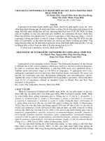
Laser System (HPLS) and Gamma Beam System (GBS). Fig. 1.1 expresses the sketch
of ELI-NP machines and experimental areas. The HPLS is designed for the following
study cases [1, 2, 3]:
ã The E1 Area host experiments of 2ì10 PW laser with high density targets
for production of extremely high fluxes of protons and high-Z ions, as well as
neutrons and their use in nuclear physics research and applications.
• The E5 experimental area is dedicated for experiments of materials irradiation
with simultaneous, mixed types of nuclear radiation produced by two 1 PW/1
Hz laser beams.
• The E6 experimental area will be dedicated to strong-field quantum electrodynamics (QED) experiments.
Meanwhile, the study of photofission and the production of RIB are provided
by the Gamma Beam System, and discussed in the following subsections.
5
Figure 1.1: Sketch of the ELI-NP machines and experimental areas. HPLS High Power
Laser System; OPCPA: Optical Parametric Chirped Pulse Amplification; XPW: Cross
Polarised Wave system; LBTS: Laser Beam Transport System; GBS Gamma Beam
System; DPSSL: Diode Pumped Solid State Laser; E1-E8 Experimental areas. [3]
1.1.1. Gamma Beam System
A highly-polarized (≥ 95%) tunable mono-energetic γ beams of spectral density
of 104 photons/(s.eV ) in the range from 200 keV to 19.5 MeV with a bandwidth of
≥ 0.3% [3, 2, 5, 6] will be produced by ELI-NP GBS. These γ beams will be produced
through laser Compton backscattering (CBS) off an accelerated electron beam delivered
by a linear accelerator. The Compton backscattering (also called inverse Compton
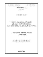
scattering) is considered as ”photon accelerator”. Fig. 1.2 shows the geometry of the
CBS between a laser photon EL energy, incident at angle θL respect to the electron
beam direction, and a relativistic electron with energy Ee . The energy of out-going
6
Figure 1.2: Geometry of the inverse Compton scattering of a laser photon on a relativistic electron.
gamma scattered at an angle θγ is given by
Eγ (θγ ) = 2γe
where γe =
1 + cosθL
1 + (γe θγ )2 +
4γe EL
me c2
EL
(1.1)
1 − (ve /c)2 is the Lorentz factor for electron, ve is the electron velocity,
me is the rest mass of the electron, and c is the speed of light.
Eq.(1.1) implies that by using a suitable collimator placed at certain θγ angle,
one can select the energy of gamma beam.
As shown in Fig. 1.1, the ELI-NP gamma beam uses a green laser 0.4 J pulse
energy with the wavelength λ = 515nm, corresponding to an incident photon energy
EL = 2.4 eV. The maximum energy, which a scattered photon can gain is achieved
in head-on collisions, θL = 0. In case of ELI-NP gamma beam, with a given Ee , the
maximum energy of gamma is [6]:
Eγ max (Ee ) = 9.55eV (1 +
Ee 2
)
m e c2
(1.2)
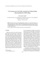
Fig. 1.3 presents two types of beams that will be delivered at ELI-NP. The broad
gamma beam displayed with blue dots has the energy range 10 − 18.5 MeV. It was
obtained by using Ee = 720M eV and collimating the beam below 0.7 mrad with a lead
collimator. The red dots in Fig. 1.3 presents the pencil beam with the narrow energy
range around 12.9 MeV. The pencil beam was obtained by setting Ee = 600M eV and
collimating the beam below 0.09 mrad. The energy spectra of these two beam types are
7
Figure 1.3: The simulated results for energy-angle correlation for two gamma beams:
a broad beam up to 18.5 MeV collimated below 0.7 mrad (blue) and a pencil beam
up to 12.9 MeV collimated below 0.09 mrad (red). The pencil beam is enclosed in a
dashed red box for visibility. [6]
shown in Fig. 1.4. The spectrum of broad gamma beam covers most of the Giant Dipole
Resonance region of Uranium and Thorium [7], making it suitable for the production
of exotic neutron-rich nuclei by photofission. Meanwhile, the narrow beam-type will
be suitable for experiments that demand a quasi-monochromatic gamma beam.
Bases on such kinds of gamma beams, ELI-NP GBS will provide the following
experiments [10, 3]:
• NRF experiments: The Nuclear Resonance Fluorescence (NRF) technique is an
outstanding tool for the investigation of low-lying dipole excitations in atomic
nuclei and provides a specific research niche for the ELI-NP facility. In experiments, the pencil gamma beams scattered off bound nuclear state will provide
access to targets that are available in small quantities and will open the actinide
8
Figure 1.4: The energy spectra of the broad beam between 10–18.5 MeV (blue squares)
and of the pencil beam at 12.9 MeV (red circles) from Fig. 1.3 [6]
.
region for NRF studies.
• Photonuclear Reaction: The ELI-NP pencil beam makes it a precise tool for
studies the characteristics of photonuclear reactions, such as cross-section, Isomer ratio, reaction yield.
• Experiments above the Neutron Separation Threshold: The brilliant, narrowwidth, highly-polarized γ-ray beam will provide an opportunity to study the
nuclear photo-response at and above the particle separation threshold, such as
the pygmy dipole resonance (PDR) at and above the particle threshold, which
is essential for nucleosynthesis in astrophysics [2, 11, 3].
• Nuclear Astrophysics Studies: The γ-induced nuclear reactions of astrophysical,
such as 7 Li(γ, t)4 He,
16 O(γ, α)12 C
...
9
• Photofission experiments and the production of RIB: Because of having an
energy range that covers the whole Giant Dipole Resonant of Uranium and
Thorium isotopes [1, 2, 7], the ELI-NP gamma beam is suitable for the production of the exotic neutron-rich isotopes in the Zr-Mo-Rh light fragment region
and in the rare-earth heavy fragment region. To support this idea, an IGISOL
facility will be constructed at ELI-NP. Some parts of the works in this thesis
will help to form the conceptual design for this future IGISOL facility. In fact,
three exist three methods for the production of RIB. The reason for choosing
IGISOL technique is discussed below.
1.2. Methods for production of RIB
To address which method is suitable for producing RIB at ELI-NP, the details
of each method will be discussed as following.
1.2.1. The ISOL technique
ISOL stands for Isotope Separation Online. In the ISOL technique, the radioactive ion beams are produced via light-ion-induced spallation or fission of a thick actinide
target. The fission reactions can be induced by thermal neutrons, fast neutrons, protons or photons. This method requires a high intensity of the primary beam and a thick
hot target. The great advantage of the thick targets is a large number of target atoms
available for the production of the ions. Even for such exotic nuclei with extremely low
production cross-sections can still be obtained. However, short-lived isotopes cannot
be obtained because of the time required for diffusion and effusion [12, 13, 14]. Another disadvantage with ISOL production is that it is difficult to achieve high beam
purity due to the many isobars of different elements produced simultaneously in the
target. Furthermore, refractory elements are in general difficult to produce due to the
high temperatures required to make them volatile, see figure 1.6 [14].
The general scheme of a typical ISOL facility is shown in Fig. 1.5 . The
production of RIB by ISOL technique is summarized as follows: the primary beam
hits the target to induce the nuclear reactions, the residual nuclei is diffused to the
10
Figure 1.5: Scheme of ISOL and In-Flight techniques [13, 14].
target surface by heating and, in the meantime is thermalized, neutralized due to thick
target. The reaction products then are re-ionized by ionization source and separated
by mass-separator.
The intensity of the RIB of interest depends on many factors, expressed as:
I = φ.σ.N.
target . source . separ . det
(1.3)
where φ is the flux of the primary beam, σ is the reaction cross section, N is the
number of atoms in the target,
source
target
is the element release efficiency from the target,
is the efficiency of the ion source,
separ
is the separation efficiency and
det
is
the efficiency of the detection system.
1.2.2. The in-flight method
The lower drawing in Fig. 1.5 expresses the scheme of In-Flight technique. In
this method, the fragmentation or fission of intense heavy-ion beams in a thin target
made of light elements such as carbon and beryllium was used for the production of
RIB. The thin target allows the fragments to release from the target surface still at
very high velocity and forward momentum which is exploited for mass separation and
study or further reactions. An advantage of this method, which is opposite to ISOL
11
Figure 1.6: Boiling and melting point of elements
technique, is that the production of the RIBs is independent of the chemical properties
of the element. Moreover, isotopes with very short half-lives and even isomers are
available as RIBs. On the contrary, the optical properties of the RIBs are poor due
to the kinetic energy spread and their divergence that results from the production
process. Since the intensities of the heavy-ion beams are generally lower than that of
the light-ion beams used for the ISOL method, the yields of some exotic fragments
may also be somewhat lower [12].
1.2.3. Ion guide isotope separation online technique
Figure 1.7 illustrates the principle of IGISOL method based on the very beginning design. The idea of this technique is that the nuclear reaction products which
release from the target into gas will be slowed down and thermalized in the gas cell to
1+ charge state. The buffer gas is typically helium, argon could be used in some special
cases [13, 15]. In some senses, the IGIGOL is similar to ISOL, except for the target
part. Instead of using a thick target, in this approach, one or several thin targets are
12
Figure 1.7: The principle of IGISOL method [15]
used. The release ions are swept by the gas flow out of the cell and injected through a
pumped electrode system into the isotope separator [14, 15].
The thickness of the target is limited to the range of the recoil ion in the target
to obtain the highest release efficiency. The range, for instance, is of the order of 1
mg/cm2 for fusion-evaporation residues and 15 mg/cm2 for fission fragments [15].
1.2.4. Method for production of RIB at ELI-NP
At ELI-NP the RIB will be created through the photofission process, namely,
the incident particle will be gamma. Therefore, as mentioned in subsection 1.2.2, the
In-flight method is not suitable. The ISOL method seems to be usable for the incident
particle of gamma. However, at ELI-NP, the RIB will be dedicated to studying the
exotic neutron-rich isotopes in the Zr-Mo-Rh region which is the refractory elements.
As shown in Fig. 1.6, Zr-Mo-Rh region has a very high boiling and melting point.
Hence, they can not be diffused to the target surface by heating. As a consequence,
the ISOL method is not the candidate for the production of RIB at ELI-NP.
Meanwhile, by using thin targets, the IGISOL method can be used for the
production of RIB in the refractory region. Therefore, at ELI-NP an IGISOL facility