Kỹ thuật khâu trong phẫu thuật nhãn khoa
Bạn đang xem bản rút gọn của tài liệu. Xem và tải ngay bản đầy đủ của tài liệu tại đây (11.65 MB, 152 trang )
Marian S. Macsai (Ed.)
Ophthalmic Microsurgical Suturing Techniques
Marian S. Macsai (Ed.)
Ophthalmic
Microsurgical
Suturing Techniques
With 289 Figures, mostly in Color
123
Marian S. Macsai, MD
Professor and Vice Chair Ophthalmology
Northwestern University
Chief, Division of Ophtho
Evanston Northwestern Healthcare
2050 P ngsten Rd.
Glenview, Il 60025
USA
ISBN-10 3-540-28069-3 Springer Berlin Heidelberg New York
ISBN-13 978-3-540-28069-9 Springer Berlin Heidelberg New York
Library of Congress Control Number: 2006935423
is work is subject to copyright. All rights are reserved, whether the whole or part of the material is con-
cerned, speci cally the rights of translation, reprinting, reuse of illustrations, recitation, broadcasting, repro-
duction on micro lms or in any other way, and storage in data banks. Duplication of this publication or parts
thereof is permitted only under the provisions of the German Copyright Law of September 9th, 1965, in its
current version, and permission for use must always be obtained from Springer-Verlag. Violations are liable for
prosecution under German Copyright Law.
Springer is part of Springer Science+Business Media.
Springer.com
© Springer-Verlag Berlin Heidelberg 2007
e use of general descriptive names, registered names, trademarks, etc. in this publication does not imply,
even in the absence of a speci c statement, that such names are exempt from relevant protective laws and regu-
lations an therefore free general use.
Product liability: e publishers cannot guarantee the accuracy of any information about dosage and applica-
tion contained in this book. In every individual case the user must check such information by consulting the
relevant literature.
Editor: Marion Philipp, Heidelberg, Germany
Desk Editor: Martina Himberger, Heidelberg, Germany
Production: LE-T
E
X Jelonek, Schmidt & Vöckler GbR, Leipzig, Germany
Illustrations: Albert R. Gattung + Regine Gattung-Petith, Edingen-Neckarhausen, Germany
Typesetting: Arnold & Domnick, Leipzig, Germany
Cover Design: Frido Steinen-Broo, EStudio Calamar, Spain
Printed on acid-free paper 24/3100/YL 5 4 3 2 1 0
This eBook does not include ancillary media that was packaged with
the printed version of the book.
Dedication
For my husband, Jack,
and his never ending support and love.
For Ezra, Max and Emma,
my continued sources of
inspiration and joy.
For my parents who taught me
to learn, to teach and to enjoy life.
Preface
In any surgical eld, the importance of suturing is self-
evident. In eye surgery, due to the lack of elasticity of
the tissues and the in uence of sutures on the visual
outcome, proper microsurgical suturing technique is
paramount. Inappropriate or careless suture placement
and knot tying can impact visual function. If wound
construction and closure are not astigmatically neutral,
the visual outcome will be altered and further surgical
intervention may be required. Wound related compli-
cations are more severe in the eye than in the skin. e
close proximity of tissues allows for rapid spread of in-
fection and the limited blood supply inhibits treatment.
e same limited blood supply alters wound healing.
e translation of hand tying techniques, intro-
duced in every medical school curriculum, to micro-
surgical instrument tying is not obvious. Essential dif-
ferences exist in all aspects of ophthalmic microsurgical
suturing techniques, from the use of the microscope
itself to the instrumentation, tissue tactics, suture ma-
terial and knot construction. e experienced surgeon
shares the challenges that face surgeons in training, as
they attempt to master new skills and handle more
complicated cases. e role of wound closure and su-
turing techniques are basic building blocks for every
ophthalmic surgical procedure. Breaking down the
complexity of microsurgical suturing to each of the
numerous components required for tissue apposition
that does not alter the function of the eye or impair the
surgical outcome is the goal of this text.
Expert surgeons from di erent specialties have con-
tributed their time and knowledge to the creation of
this text. e uniform layout with key points identi ed
at the beginning of each chapter allows the reader to
quickly locate a particular technique. e authors have
made great e orts to describe each technique in a step-
by-step fashion, so that the reader can reproduce the
technique on their own. Accompanying digital video
clips of surgical footage clarify and demonstrate the
di erent techniques. Mastery of basic and advanced
ophthalmic microsurgical suturing techniques will fa-
cilitate expansion of any surgeon’s armamentarium.
As ophthalmic surgery advances, a variety of skills
are needed for the surgeon to stay current. is text
o ers the reader ophthalmic microsurgical suturing
techniques that decrease the risk of postoperative in-
fection and result in astigmatically neutral wound clo-
sure. Equipped with the knowledge of alternative tech-
niques, when complications arise, the reader can
decrease the need for further surgical intervention and
improve their surgical outcomes.
Acknowledgements
A text of this diversity is not possible without the input
and help of many authors. I thank each of the authors
who have freely contributed their expertise on an ex-
tremely tight schedule. Each was patient with the con-
tinuous revisions, illustrations, and video issues. Your
continued help and support made this idea a reality. I
could not have assembled all this material without
Peggy Dow, who kept me organized and on track. A
special thanks goes to all the people at Springer who
gave so much to this project, especially Marion Philipp
and Martina Himberger. I thank Renee Gattung for
her expert illustrations, and Patrick Waltemate at
LE-TeX for his patience.
Contents
1 The Physics of Wound Closure,
Including Tissue Tactics . . . . . . . . . . . . . . . . . . . . . . 1
Larry Benjamin
2 Needles, Sutures, and Instruments . . . . . . . . . . . . 9
Jennifer H. Smith and Marian S. Macsai
3 Knot-Tying Principles and Techniques . . . . . . . . 21
Anthony J. Johnson and R. Doyle Stulting
4 Microsurgical Suturing Techniques:
Closure of the Cataract Wound . . . . . . . . . . . . . . . 29
Scott A. Uttley and Steven S. Lane
5 Suturing an Intraocular Lens . . . . . . . . . . . . . . . . 37
Julie H. Tsai and Edward J. Holland
6 Corneal Suturing Techniques . . . . . . . . . . . . . . . . 49
W. Barry Lee and Mark J. Mannis
7 Trauma Suturing Techniques . . . . . . . . . . . . . . . . 61
Marian S. Macsai and Bruno Machado Fontes
8 Iris Reconstruction . . . . . . . . . . . . . . . . . . . . . . . . . . 71
Steven P. Dunn and Lori Stec
9 Sclera and Retina Suturing Techniques . . . . . . . 85
Kirk H. Packo and Sohail J. Hasan
10 Glaucoma Surgery Suturing Techniques . . . . . 101
Joanna D. Lumba and Anne L. Coleman
11 Amniotic Membrane Suturing Techniques . . . 107
Sche er C. G. Tseng, Antonio Elizondo,
and Victoria Casas
12 Strabismus . . . . . . . . . . . . . . . . . . . . . . . . . . . . . . . . 117
Mark J. Greenwald
13 Refractive Surgery Suturing Techniques . . . . . 129
Gaston O. Lacayo III and Parag A. Majmudar
14 Pterygium, Tissue Glue, and the Future
of Wound Closure . . . . . . . . . . . . . . . . . . . . . . . . . . 135
Sadeer B. Hannush
Subject Index . . . . . . . . . . . . . . . . . . . . . . . . . . . . . . 141
List of Contributors
Larry Benjamin
Department of Ophthalmology
Stoke Mandeville Hospital
Mandeville Road
Aylesbury, Bucks HP21 8AL, UK
E-mail:
Victoria Casas
Ocular Surface Center, P.A.
7000 SW 97th Ave., Ste. 213
Miami, FL 33173-1492, USA
E-mail:
Anne L. Coleman
Jules Stein Eye Institute
100 Stein Plaza, #2118
Los Angeles, CA 90095-7065, USA
E-mail:
Steven P. Dunn
Michigan Cornea Consultants
29201 Telegraph Rd., Ste. 101
South eld, MI 48034-7630, USA
E-mail:
Antonio Elizondo
Ocular Surface Center, P.A.
7000 SW 97th Ave., Ste. 213
Miami, FL 33173-1492, USA
Bruno Machado Fontes
Av. des Americas 2300 / B, cs 27
Rio de Janeiro, RJ, Brazil 22640-101
E-mail: ;
brunofontes@o almo.epm.br
Mark J. Greenwald
Department of Ophthalmology and Visual Science
University of Chicago
5841 S. Maryland Avenue, M/C 2114
Chicago, IL 60637, USA
E-mail:
Sadeer B. Hannush
Cornea Service, Wills Eye Hospital
Je erson Medical College, Philadelphia, PA
Correspondence:
400 Middletown Blvd. Suite 110
Langhorne, PA 19047, USA
E-mail:
Sohail J. Hasan
Ingalls Hospital Professional Bldg.
71 West 156th St., Ste. 400
Harvey, IL 60426, USA
Edward J. Holland
CEI-NKY
580 South Loop Rd., Ste. 200
Edgewood, KY 41017, USA
E-mail:
Anthony Johnson
Cornea/Refractive Surgery
SAUSHEC Ophthalmology
3851 Roger Brooke Drive
Fort Sam Houston, Tx 78234, USA
E-Mail:
Gaston O. Lacayo III
Rush University Medical Center
Department of Ophthalmology
1725 W. Harrison St., Ste. 928
Chicago, IL 60612, USA
E-mail:
Stephen S. Lane
280 N. Smith Ave., Ste. 840
St. Paul, MN 55102, USA
E-mail:
W. Barry Lee
Eye Consultants of Atlanta
95 Collier Rd., Ste. 3000
Atlanta, GA 30309, USA
E-mail:
XIV
Joanna Lumba
1101 Welch Road, Suite B2
Palo Alto, CA 94304, USA
E-mail:
Marian S. Macsai
Professor and Vice Chair Ophthalmology
Northwestern University
Chief, Division of Ophtho
Evanston Northwestern Healthcare
2050 P ngsten Rd.
Glenview, Il 60025, USA
Parag A. Majmudar
Rush University Medical Center
Department of Ophthalmology
1725 W. Harrison St., Ste. 928
Chicago, IL 60612, USA
E-mail:
Mark J. Mannis
Department of Ophthalmology
University of California
4860 Y St., Suite 2400
Sacramento, CA 95817, USA
Kirk H. Packo
Rush University Medical Center
Department of Ophthalmology
1725 W. Harrison St., Ste. 945
Chicago, IL 60612, USA
E-mail:
Jennifer Hasenyager Smith
2032 Valor Ct.
Glenview, IL 60026, USA
E-mail:
Lori Stec
Beaumont Eye Institute
3601 W. irteen Mile Road
Royal Oak, Michigan 48073, USA
R. Doyle Stulting
Emory Vision
875 Johnson Ferry Road
Atlanta, GA 30342, USA
E-mail:
Julie H. Tsai
University of South Carolina School of Medicine
Dept of Ophthalmology
Four Medical Park, Suite 300
Columbia, SC 29203, USA
E-mail:
Scheff er C. G. Tseng
Ocular Surface Center, P.A.
7000 SW 97th Ave., Ste. 213
Miami, FL 33173-1492, USA
E-mail:
Scott A. Uttley
St. Paul Eye Clinic
2080 Woodwinds Dr.
Woodbury, MN 55125-2523, USA
E-mail:
Chapter 1
Key Points
Principles of wound closure vary, depending
on whether the wound is extraocular or in-
volves opening the pressurized globe and sub-
sequent closure. Preparation, avoidance of
infection, and maintaining wound integrity
are vital in good wound management.
When suturing, the tissue should be well con-
trolled to stabilize the area through which the
needle passes. Desired results are best achieved
when this is done.
Closure of the skin of the eyelid is comparable
to skin closure elsewhere. Di erences exist in
the struc ture detail(s) included in the closure.
ere are a num ber of techniques for working
with the lid, con junctiva, and cornea and
sclera.
Because of the in exible nature of the cornea
and sclera, tissue suturing here requires pre-
cise suture placement.
Successful ophthalmic wound closure results
from proper technique modi cation and su-
ture tension.
1.1
Introduction
e closure of wounds in surgery relies on apposing
surfaces and planes of tissue so that they can heal in an
appropriate fashion. Knowledge of the biology of
wound healing is important, as is being able to modify
the processes involved to achieve the desired wound
architecture in an appropriate time. When considering
wound construction or repair in the cornea, wound
anatomy and healing can both have a dramatic e ect
on visual outcome a er the surgery because of the ef-
fect of surgically induced astigmatism on the corneal
surfaces. Similarly, poor wound repair on the eyelid
margins can have a long-term e ect on the ocular en-
vironment by a ecting lid closure and tear ow. is
chapter addresses the forces and vectors involved in
wound closure, the tactics used to achieve the desired
e ects, and how these relate to clinical principles.
•
•
•
•
•
1.2
Wound Architecture
1.2.1
Principles of Wound Closure
e principles of wound closure vary, depending on
whether the wound is extraocular or involves opening
the pressurized globe and subsequent closure. Para-
mount in the sequence of good wound management is
preparation. is means adequate cleaning of surgical
surfaces, excellent aseptic technique, as well as thor-
ough postoperative care.
Avoiding infection is the best way to ensure wound
integrity and healing in a timely fashion. In the eyelids,
infection a er surgery is uncommon, as there is a plen-
tiful blood supply, but in the cornea and cavities of the
globe, infection will last longer, cause more devasta-
tion, and be more di cult to eradicate.
One of the overriding principles of wound closure
is to keep the integrity of the body cavities intact and
prevent ingress of infectious agents. In addition, when
suturing the optical surfaces of the eye (any part that
a ects corneal curvature), care must be taken to avoid
excessive astigmatic change while maintaining the in-
tegrity of the globe.
Choice of instrumentation is important, as some
instrument tips may damage the delicate corneal tis-
sues more than others. Toothed forceps will grasp tis-
sue well but will puncture it. Notched forceps are more
gentle and may be preferred, but under some circum-
stances where the tissue is edematous (such as a er
trauma), multiple attempts to grasp the tissue with
notched forceps may result in further maceration and
swelling, whereas a single sure grasp with toothed for-
ceps may be preferable.
Microsurgery is distinctly di erent from general
surgery. e operating microscope forces the surgeon
to assume a particular posture that o en must be
maintained for several hours; the surgeon should sit in
a natural position, leaning slightly forward, with a
straight back and relaxed shoulders. Both feet should
be at on the oor. e visual eld is restricted, as is
the space for manipulation between the microscope
The Physics of Wound
Closure, Including Tissue
Tactics
Larry Benjamin
1
2
and the operative eld. e operating microscope con-
sists of the following elements: oculars, beam splitter,
magni cation system, and objective. Both focus and
magni cation should be adjustable with a remote foot
control. e entire surgical eld can be surveyed sim-
ply by dropping one’s gaze to the operative eld.
e function of sutures is to maintain apposition of
wound edges arti cially until scar tissue has attained
su cient strength. e ideal suture must appose the
incised tissue edges in their normal anatomic position
and provide adequate compression and minimal space
for the scar tissue to bridge. Until formation of s car
tissue is complete, the suture must maintain this ap-
position when external forces are applied. Simple in-
terrupted suture presses the wound margins together
and tends to assume a circular shape when tightened.
When overtightened or overcompressed, the posterior
aspect of the wound may gape, creating a stula. Over-
compression may cause the surgeon to place numerous
unnecessary sutures to keep the wound watertight.
Simple interrupted sutures produce inversion of the
wound edges as the suture assumes a circular shape.
Interrupted mattress sutures may produce inversion or
eversion of the wound edges, depending on their
placement and the degree of tightening. Continuous
sutures atten a convex wound and tend to straighten
out curved incisions. e continuous suture will de-
form the surface when the suture bites are placed ir-
regularly. Irregular sutures result from unequal suture
depth placement, unequal length of suture passes and
nonradial suture placement.
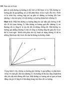
90°
Radial to
the wound
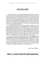
Fig. 1.1 e needle is passed perpendicular to the surface of
the tissue and exists equidistant from the point of entry when
viewed form the anterior perspective of the laceration
a
b
c
Fig. 1.2 a A er the knot is tied and the ends are cut short,
the suture is grasped with smooth forceps and rotated into
the tissue; care must be taken to avoid a twisting motion that
may torque the tension on the suture and result in a shearing
force that tears the tied suture. b e knot is then grabbed
and rotated in the reverse direction. c e suture knot is now
just beneath the surface of the tissue, and the ends extend
away from the wound. is placement of the knot will facili-
tate removal as long as the knot is pulled out in a manner
that does not require the knot to traverse the wound inter-
face
Larry Benjamin
3
1.3
Suture Placement
Tissue must be properly held in order to stabilize the
area of tissue the needle is driven through. If this ma-
neuver of passing the needle through the wounds edge
is controlled, the desired results are achieved (Figs. 1.1
and 1.2). Using 0.12 mm forceps, the tissue should be
held with the two-teeth side of the forceps on the same
side of the tissue through which the needle is being
driven.
e needle should be two thirds of the way from the
point of the surgical needle and held at a 90° angle
from the needle holder. e needle must be parallel to
the tissue plane (deviation will lead to tissue laceration
with a side cutting spatulated needle), and slip (if not
over tightend) or surgeon‘s knots may be used when
tissue is under tension. A er the wound is closed, the
initial sutures may be replaced with astigmatically
neutral sutures, surgeon‘s knots (2:1:1), at the desired
tension, to avoid over compression of tissue, which can
easily happen with slip knots that are tied to tightly.
1.3.1
Suture Technique
e suture passes should be of equal depth in the tissue
on either side of the wound and of equal length. In this
way, the wound will appose correctly without wound
override or inducement of astigmatism. e greatest
accuracy is achieved when the needle is inserted per-
pendicular to the tissue surface and emerges perpen-
dicular to the wound surface (Fig. 1.3). is placement
causes minimal shi of the wound surface when the
suture is tied. e needle can be passed in two steps.
First, it is inserted perpendicular to the tissue surface,
and it emerges perpendicular to the wound surface.
e needle should be brought out through the wound
surface, and then reinserted into the opposing wound
surface perpendicular to the wound surface such that
it exits perpendicular to the tissue surface. When using
this technique, it is sometimes di cult for the surgeon
to determine the proper insertion site in the opposing
wound surface. Furthermore, it is important for the
surgeon to consider that the depth at which the exiting
needle exits should be the same depth as when the
needle enters the opposing wound surface. If the sur-
geon inadvertently changes the direction of the needle
when entering the opposing wound surface or exits
and enters at di ering depths, the resultant torque on
the tissue will displace the entire wound. Easier pas-
sage of the needle tip through the tissue at 90 degrees
can be accomplished by everting the distal lip of the
wound so the depth of the wound can be accurately
ascertained. is allows a atter trajectory of the nee-
dle through the tissue nd enables the surgeon to see
the depth of both sides of the wound and accurately
position the needle into the second half of the wound.
e incised tissue is xated with xation forceps,
and the needle position must be adjusted according to
the amount of tissue deformation caused by the for-
90°
90°
Correct
90°
90°
Incorrect Tissue override
a
bc
AB
AB
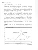
Fig. 1.3 A needle is passed in two steps. a e needle is rota-
ted posteriorly, and it enters the tissue surface in a perpen-
dicular fashion (90° angle) and emerges perpendicular to the
wound suture. b e same angle of penetration is followed
when the apposing tissue is entered perpendicularly and the
needle again emerges at a 90° angle to the tissue surface. is
method causes minimal shi of the wound surface when the
suture is tied. c is equal spacing of the suture results in
correct wound apposition; unequal suture passes or bites can
result in wound override and irregular astigmatism
Chapter 1 The Physics of Wound Closure, Including Tissue Tactics
4
ceps. e tissue should be xated at the position where
the suture is to be placed, not adjacent to this position.
e needle sha must be inclined posteriorly to allow
the tip of the needle to pierce the tissue at a right angle.
A deep semicircular stitch produces a large compres-
sion zone, which limits the number of interrupted su-
tures needed to close a wound. Care must be taken not
to overtighten the sutures. Overtightening of sutures
can shorten the suture track and deform the surround-
ing tissue, which interferes with wound closure. A
single overcompressed suture can disrupt the closure
of the full length of the wound. It is better to remove an
overcompressed suture than to place numerous cor-
rective sutures to provide countertension. ese cor-
rective sutures may make the wound watertight, but
the result increases astigmatism.
1.3.2
Force Vectors of Sutures
All sutures produce vector forces that act in various
directions as the suture is tightened. e vector forces
extend in three di erent directions: perpendicular to
the wound surface, parallel to the wound margin, and
perpendicular to the tissue surface. If a suture is placed
perpendicular to the wound surface, the force vectors
cause compression in a line where the suture plane in-
tersects with the wound surface. However, if the suture
is placed obliquely, the compression vector force is an
area on the wound surface; therefore, a lateral shi of
the wound is produced. is shi is also the result of
the vector force that is parallel to the wound margin.
is force is not generated when the interrupted su-
tures are placed perpendicular to the wound. In con-
tinuous sutures, the shi ing vectors of the bridging
segments of the suture can serve to neutralize the shi -
ing forces generated by each suture bite. e third vec-
tor component, perpendicular to the tissue surface,
results in two forces in opposite direction in the simple
interrupted suture. e rst component results in ever-
sion of the wound edge, and the second portion of the
suture generates a force resulting in inversion of the
wound edge. In the simple interrupted suture, these
forces cancel each other out, and they are in opposite
directions. Continuous sutures produce both inverting
and everting forces that are cancelled out if the loops
are placed very close together, otherwise, signi cant
irregularities of the tissue surface result. An example of
the continuous suture can be found in Chap. 6.
e e ects of compressing vectors are maximal in
the suture plane and diminish farther away from the
suture. Each interrupted suture generates a zone of
compression. e compressive e ect is maximal in the
plane between the point of suture entry and suture exit
and falls o laterally. e action of the suture can be
described in terms of force triangles extending laterally
from the suture. e width of these compression zones
depends on the length of the suture bites and the degree
of suture tension a er the suture is tightened. Adequate
wound closure is achieved when the zones of compres-
sion of each interrupted suture overlap (Fig. 1.4).
1.4
Lid Wound Closure
Closure of the skin of the eyelid is similar to skin clo-
sure elsewhere, although di erences may exist in the
detail of what structures are included in that closure.
For example, incorporating the tarsal plate into the
skin suture a er a ptosis repair will cause a skin crease
to form in the appropriate place. Essentially, lid skin
closure is performed by placing a central suture, divid-
ing the wound in half, and then dividing each half in
half again. Deciding how many sutures to use depends
on their length and tension. An adequate number of
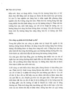
sutures have been used when the zone of compression
of each suture overlap. Figure 1.4 shows the zone of
compression for a single suture, which is the e ective
zone of closure that a suture exerts when tied at its par-
ticular tension. ese zones should overlap slightly to
ensure that the wound will not open between the su-
tures, and the closer the sutures are together, the more
the adjacent compression zones overlap and the more
secure will be the wound.
Decisions about suture placement are important in
relation to their spacing, depth, tension, and length.
A > B = Watertight closure A < B = Wound leak
A
A
B
B
Zone
of
compression
Leak Leak
Fig. 1.4 Zones of compression.
Di erent lengths of suture bites
result in di erent zones of com-
pression. When the zones of com-
pression overlap, adequate wound
closure is achieved (arrows)
Larry Benjamin
5
Usually, a suture should be symmetrical across a
wound with equal depth and length across the wound.
Suture bites are made with the needle at 90° to the tis-
sue surface. Everting the wound edge is sometimes
necessary to be able to see the placement of the needle
tip as it enters the tissue (Fig. 1.5).
is also allows a view into the depth of the wound
to ensure that the needle engages the opposite wound
edge at the same depth. e suture track will some-
times be longer than the radius of curvature of the
needle, which will make the wound pout when the
needle is in both sides of the wound (Fig. 1.6).
e length of the suture track may be important in
skin wounds, because if placed too close to the wound
edge and made too tight, then avascular necrosis of the
skin edge can occur. Skin sutures are usually tied
slightly overtight to evert the edges together so that as
healing progresses and subdermal involution of tissue
occurs, the wound edges will end up at.
1.5
Lid Margin Repair
ere are a number of di erent techniques available
for repairing lid margins, but the principles are the
same. It is important to accurately align the three sur-
faces of the lid (skin, gray line, and conjunctiva) for an
adequate time for healing to occur.
If a tarsal plate suture is used then additional skin
sutures can be removed early (1 week), but if gray line
and skin sutures are used without a cardinal tarsal su-
ture, then they must be le in for 2 to 3 weeks to allow
proper healing, especially if the wound is under ten-
sion such as when a proportion of the lid length has
been removed in tumor removal or entropion repair. A
cardinal tarsal suture should be placed horizontally
parallel to the lid margin about 1 mm from its surface
and should be within the lid substance entirely. In
other words, the suture should not protrude through
either skin at the front of the lid or conjunctiva at the
back. A well-placed tarsal suture will provide the nec-
essary strength and tension for the lid margin to heal
with no notching, and will allow early removal of sup-
plementary skin and lid margin sutures.
1.6
Conjunctiva Wound Repair
When suturing the conjunctiva, the surgeon must recog-
nize the inherent tendency of the tissue to curl. When
the conjunctival tissue curls, there is some retraction of
the conjunctival epithelium. e retraction can be o set
by countertraction on the subepithelial tissue. e epi-
thelial layer can be recognized by its distinctive vascular
pattern. Application of balanced salt solution to the cut
margin of the conjunctival tissue makes this distinction
easier because Tenon’s capsule will appear white when
the bers are hydrated with the solution. Care must be
taken to recognize the margin of the surgical dissection
when suturing conjunctiva. When countertraction is
applied, toothed forceps, such as 0.12-mm forceps, may
be necessary to determine the margin of the surgical
dissection and apply countertraction. If countertraction
is not applied properly, inadvertent suturing of epithe-
lial tissue in a subepithelial space can result in the post-
operative formation of an epithelial inclusion cyst. Con-
junctival tissue is extremely compliant, and postoperative
adherence is accomplished rapidly because of the vas-
cular substrate. Frequently, a rapidly absorbable suture,
such as 8-0 collagen or 8-0, Vicryl is used to secure the
conjunctival tissue in place.
Everted
wound edge
Needle visible
in de
p
th of wound
Fig. 1.5 Everting the wound edge
Wound pouting due
to radius of curvature
of needle being greater
than that of the bite
Fig. 1.6 Pouting of the wound
Chapter 1 The Physics of Wound Closure, Including Tissue Tactics
6
1.7
Corneal Wounds and Repair
Because of the unyielding nature of the cornea and
sclera, suturing of these tissues requires extremely pre-
cise placement of sutures. e needle track must cut
through the lamellae of the tissue. Surgical wounds can
be placed to facilitate closure, whereas traumatic wounds
o en require thinking on one’s feet at the time of repair
because of their unpredictable architecture. Sometimes
a surgical wound becomes di cult to close predictably,
for example, overenlarging a phacoemulsi cation tun-
nel to insert an implant may destabilize a supposedly
self-sealing wound and necessitate suturing. Examples
of wound architecture and closure techniques for cata-
ract wounds are detailed in Chap. 4. In order for a wound
to be self-sealing, it must create a valve-like e ect.
1.7.1
Closing the Large Limbal Wound
is can be done with interrupted sutures or a contin-
uous one. e theoretical advantage of a continuous
suture is the more even distribution of tension along
the length of the wound and thus, hopefully less astig-
matism. However, a tight continuous suture can cause
just as much astigmatism as interrupted ones, and also
have the disadvantage of being less exible in terms of
astigmatism control. If it breaks or loosens, the whole
thing must be removed and possibly replaced, whereas
selective removal of individual sutures can be useful to
adjust astigmatism.
Assuming that the wound has been made 1 mm
from the limbus and is beveled, then placement of the
rst 10-0 nylon suture is made centrally. e principle
of this stitch is that it is used to stop the wound from
opening, as opposed to keeping it closed. In principle,
the wound will, if well constructed, keep itself closed
and should heal with no astigmatism if le undis-
turbed. Clearly, patients cannot be asked to keep still
for several weeks while the wound is healing, and so
sutures are placed to keep the wound from opening. If
this suture does not equally divide the wound, it will
need to be replaced once sutures are placed on either
side of the initial wound.
A 2-1-1 con guration of square knot ( surgeon’s
knot) is used, and the rst two throws can be laid down
on the corneal surface at exactly the right tension to
stop the wound opening, as shown in Fig. 1.7.
Subsequent throws are made to lock the knot at this
tension, and it is imperative that proper square knots
are made so that the tension in the rst turns of the
knot is not disturbed. Tying a square knot will ensure
that it locks at the predetermined tension, whereas if a
slipknot is inadvertently tied, the tension will increase
as the knot slips rather than locks.
Further sutures are then placed either side of the
rst with equal spacing, length, depth, and tension and
for wound of 140° in length, ve sutures are usually
adequate.
Overtightening a corneal suture will steepen the
central curvature of the cornea and induce steepening
in that meridian (causing a myopic shi in that merid-
ian). Leaving them very loose may allow the corneal
wound to “slip” (open slightly) and atten the merid-
Fig. 1.8 A simple butter y or cross-stitch is all that is needed
to close the wound, which will then e ectively self seal as
intraocular pressure is restored
Larry Benjamin
Fig. 1.7 A 3-1-1 con guration of square knot ( surgeon’s
knot) is used, and the rst three throws can be laid down on
the corneal surface at exactly the right tension to stop the
wound opening
7
ian concerned. It is therefore very important to make
the wound self-sealing and tension the sutures to stop
the wound from opening.
1.8
Suture Placement to Close a Phaco -
emulsifi cation Wound
Occasionally a phacoemulsi cation wound is extended
too far and becomes unstable. A simple butter y or
cross-stitch is all that is needed to close the wound,
which will then e ectively self-seal as intraocular pres-
sure is restored, and the suture can be removed at a
week (Fig. 1.8). A mattress suture is a good alternative
to closing the wound, without inducing astigmatism.
1.9
Corneal Transplant Suturing
All transplant surgeons know that it is not possible to
produce astigmatism-free wounds reliably. e prin-
ciples of suturing these wounds include the need for a
watertight wound, with sutures that are placed equally
deep in both host and donor tissue. Full thickness su-
tures should be avoided (endothelial damage and a po-
tential track for infection into the anterior chamber).
A running suture should have even tension for 360°,
and all knots should be buried. A continuous suture
provides relatively even tension and is quicker to per-
form. Interrupted sutures should be used when infec-
tion or in ammation is present, as they can be selec-
tively removed if necessary. e torque induced by a
continuous suture can be counteracted by an opposite
running suture and some surgeons will use a mixture
of 10-0 nylon and 11-0 nylon to provide this torque
and countertorque.
1.10
Wound Closure in Trauma
e unpredictable nature of traumatic wounds means
that closure requires careful thought. Wounds may
shelve in di erent directions from one end to the other,
and reliable watertight closure requires various sutur-
ing techniques during the procedure. A typical shelved
wound is shown in Fig. 1.9, and it makes sense to place
the rst suture in the most unstable portion of the
wound. In this case, centrally, to make the wound more
stable, which makes subsequent closure easier.
Chapter 7 demonstrates the approach that is needed
with a shelved wound to ensure accurate wound edge
apposition. e critical point is to make the depth of
the suture equal in the deep part of the wound, or else
overriding of the wound edge may occur. An easy way
to ensure that equal depth is achieved is to keep the
length of the deep portion of the suture equal and the
epithelial portion unequal.
1.11
Conclusion
Closure of some ophthalmic wounds is similar to other
areas of surgical practice. However, speci c di erences
exist in wounds relating to the globe and the e ect that
suturing can have on vision by dramatically disturbing
optical surface curvature resulting in astigmatism.
Modi cation of technique and suture tension is critical
if satisfactory functional as well as anatomical results
are to be obtained.
Fig. 1.9 A typical shelved wound
Chapter 1 The Physics of Wound Closure, Including Tissue Tactics
Chapter 2
Needles, Sutures,
and Instruments
Jennifer Hasenyager Smith and Marian S. Macsai
2
Key Points
Needle material, diameter, curvature, and
point style all contribute to needle function
and should be considered relative to the goal
of suturing and tissue type when selecting a
needle.
Suture material and diameter determine
strength, handling, adsorbability, knot secu-
rity, and tissue reactivity. Together with the
tissue type and goal of suturing, these charac-
teristics should be considered when selecting
suture material.
Instruments used for microsuturing should
be of the appropriate size and style to facilitate
safe, e ective suturing in light of the speci c
needle, suture, and tissue involved.
New technology in suturing instrumentation
includes suture swaged to needles of the same
or smaller diameter, suture coated with bioac-
tive glass and antibacterials, and microinci-
sion instruments for intraanterior chamber
suturing.
2.1
Introduction
Information about suture materials and needles is im-
portant, as inappropriate use of a material or needle
type can lead to wound breakdown or tissue injury.
For example, following trauma, the use of an absorb-
able suture to repair a scleral rupture can lead to wound
dehiscence a few weeks a er the repair, and the use of
a cutting or reverse-cutting needle on the sclera can
lead to choroidal or retinal injury at the time of repair.
e surgeon faces several decisions when closing a
wound. ese decisions include choice of suture and
needle, placement of sutures, and type of knot.
•
•
•
•
2.2
Needles
Prior to 1959, eyed needles were commonly used in
the United States for ocular suturing [48, 61]. ese
needles worked in a similar fashion to the common
clothes sewing needles in current use. e use of an
eyed needle threaded with suture resulted in a double
thickness of suture being pulled through the needle
tract; however, only a single-thickness of suture was
le tied in the incision. is was problematic in that
the needle tract was resultantly larger in diameter than
the suture and was prone to leakage. e needle swage,
or permanent attachment of the suture to the needle at
the time of manufacture, which was patented in 1914
[35], eventually came into popular use and allowed for
improved techniques in ocular suturing (Tables 2.1
and 2.2).
2.3
Needle Characteristics and Selection
(See Table 2.1.)
Although the performance of a needle is determined
by its shape and its composition, needles are typically
described in manufacturers’ catalogs by shape but not
by metallurgical composition. e characteristics that
de ne a speci c needle type include curvature (1/4,
3/8, or 1/2 circle), chord length, and radius (Fig. 2.1);
linear needle length, wire diameter, and point cutting
edge (Fig. 2.2).
ere are two basic styles of needle swage (attach-
ment of suture to needle end) in use for the small nee-
dles used in microsuturing, laser drilling, or channel
xation. Laser drilling forms a hole in the trailing end
of the needle into which the suture is secured. Channel
xation involves the use of a tool that forms a planed
cut that is half the thickness of the needle wire along
the trailing end of the needle. e cut is approximately
four times the length of a laser-bored hole, and the su-
ture is xed to a depression in the cut area. e process
results in a groove and an unevenly rounded surface at
the needle end. A disadvantage of the channel- xed
needle is that the suture can be loosened or the swage
10
can be deformed when grasped by a needle holder at
the swaged area. Laser-drilled swages have less wire
bulk removed during manufacture and have a smooth-
er trailing needle end. ey are therefore less easily
deformed when grasped near the trailing end [53]. e
relative biomechanical performance of channel-style
and laser-drilled needles was compared in two Ethicon
needles in a standardized grading system [3]. It was
shown that laser-drilled needles were both easier to
pass through a test membrane and less likely to deform
or break than channel-style needles. e authors of
that study recommended laser drilling for all needles.
e properties of an ideal surgical needle have been
summarized as: (1) su ciently rigid so that it does not
bend; (2) long enough so that it can be grasped by the
needle holder for passage and then be retrieved with-
out damage to its point; (3) of su cient diameter to
permit a slim-point geometry and a sharp cutting
edge, resulting in a tract large enough to allow the knot
Jennifer Hasenyager Smith • Marian S. Macsai
Table 1. Basic surgical needle types and their characteristics. References [29, 32, 40, 42, 59]
Needle
Type
Bite Cross section Side
cutting
Y/N
Tissue tract Procedure(s) Comment
1/4, 3/8
circle
Large/
shallow
1/2 circle Short/deep
Spatula trapezoid Y Intralamellar
plane
Lamellar keratoplasty,
cataract incisions,
strabismus surgery, etc
Standard
cutting
Triang le,
point up
Y Tracks
super cially
Scleral gra s, corneal
sutures, etc
Tough tissues,
full-thickness bites.
Sharper than reverse
cutting.
Reverse
cutting
Triang le,
point down
Y Tracks
deeply
Scleral gra s, corneal
sutures, etc
Tough tissues,
full-thickness bites
Standard
cutting/
beveled edge
Triang le,
point up
Y Tracks
super cially
Scleral gra s, corneal
sutures, etc.
Tough tissues,
full-thickness bites.
Sharper than
stan dard cutting or
reverse cutting.
More bending than
non-beveled.
Taper-point circle N Smaller than
trailing
suture
Trabeculectomy, iris
suturing
Not good for tough
tissues
Tapercut Tip: triangle;
Body: round
Y Smaller than
trailing
suture
Trabeculectomy Combination of
reverse-cutting and
taper point.
Penetrates tissues
more easily but still
watertight.
Table 2.2. Common microsurgical needle characteristics
Model
Circle Needle
Type
Wire
(mm)
Length
(mm)
CIF-4
¼Taper
Point
0.20
13.34
PC-7
¼Taper
Point
0.23
13.34
BV 100-4
3/8 Taper
Point
0.10
5.11
STC-6
Straight Spatula 0.15
16.00
SC-5
Straight Spatula 0.15
16.15
CTC-6
¼ Spatula 0.15
11.99
CTC-6L
¼ Spatula 0.15
14.00
CS160-6
3/8 Spatula 0.15
5.33
11
to be buried; and (4) as nontraumatic as possible [43].
Optimal surgical needles should also be composed of
materials that resist dulling and permanent deforma-
tion during passage through tissue. At the same time,
the material should not be so rigid that it is brittle and
likely to fracture easily if stressed.
Needles can additionally be evaluated in terms of
resistance to bending and ductility. A needle’s resis-
tance to bending can be objectively measured with a
standardized procedure that generates a graph of force
required to reversibly and irreversibly bend a needle
[2, 14]. Factors a ecting the resistance to bending of a
needle include needle diameter, needle material, and
the manufacturer. Needle ductility refers to the amount
of deformation that a needle can withstand without
breaking [18]. Superior ductility grading was seen in
needles made from American Society for Testing and
Materials (ASTM) 45500 alloy and nished with the
electrohoning process [1, 14].
In studies of sharpness, needles with longer, more
narrow cutting edges and needles made from ASTM
alloy 45500 were the sharpest [14, 57]. e standard
cutting edge and reverse-cutting edge needles both
have triangular cross sections, with two lateral cutting
edges that can in uence needle sharpness [9]. e third
cutting edge of a standard cutting needle is located on
the concave surface (also referred to as the inner, or top,
surface) of the curved needle. e reverse-cutting nee-
dle has its third cutting edge on the convex surface
(outer, or bottom, surface) of the needle (Fig. 2.2). In
standardized sharpness comparisons, the standard cut-
ting needle was found to be sharper than the reverse-
cutting needle [59], and a modi ed standard cutting
edge needle with beveled edges and correspondingly
narrower cutting edges (Fig. 2.3) was found to have fur-
ther enhanced sharpness both in vitro through a syn-
thetic membrane and in vivo for suturing skin lacera-
tions in the emergency room [29]. e narrower cutting
angle along the concave surface facilitates tissue pene-
tration [32]. However, it has also been recently shown
that in comparison with triangular and diamond-
shaped tips, a bevel tip causes more bending and is
more easily a ected by tissue density variations [40].
Taper-point needles ( cardiovascular or BV needles)
are frequently used to close conjunctiva when a water-
tight suture line is desired, such as in trabeculectomy
[27]. Taper-point needles with two combined radii of
curvature are also available and provide greater accu-
racy to a controlled depth and length of bite than does
a curved needle with a single radius of curvature [15].
A modi cation of the taper-point needle, the Tapercut
(Fig. 2.2F), combines a short reverse-cutting tip with a
taper-point body. e resulting needle is sharper and
initially penetrates tissue more easily than a taper
point, and is still able to create tighter needle tracts
with more watertight closures than would a reverse
cutting needle. In order to create the smallest possible
ratio of needle-to-suture diameter, polypropylene su-
ture material can be extruded to create a tapered swage
end of signi cantly smaller diameter than the remain-
der of the suture, allowing a channel swage to a needle
of minimal diameter ([60]; Fig. 2.4).
Point
Swage
Chord length
Radius
Diameter
Needle body
Total length
Fig. 2.1 Speci cations terminology for surgical needles.
(Reprinted from Steinert RF. Cataract Surgery, Techniques,
Complications, and Management, 2nd Edition, p 53. © 2004,
with permission from Elsevier)
ba
d
f
c
e
Fig. 2.2 Schematic illustrations of surgical needle types. a
Conventional cutting needle, b reverse cutting. c, d Spatula
needles. e Taper-point needle. f Tapercut needle. (Reprinted
from Steinert RF. Cataract Surgery, Techniques, Complica-
tions, and Management, 2nd Edition, p 52. ©2004, with per-
mission from Elsevier)
Chapter 2 Needles, Sutures, and Instruments
12
2.4
Sutures
In the history of general surgery, many materials have
been used as sutures, including horsehair, linen, silver
wire, and twine. Early improvements in suture tech-
nology included the development of catgut and silk
sutures [18, 19]. Re nements continued, including
sterilization of silk sutures and treatment of catgut
with chromic and carbolic acids to increase the dura-
tion of the suture holding strength in tissue from a few
days to weeks [21]. Synthetic materials such as nylon
and polyester became available in the 1940s. More re-
cently, additional synthetic materials such as polygly-
colic acid, polybutester, polyglactin, and polydioxa-
none have been used to make suture.
Suture material is classi ed either as adsorbable or
nonabsorbable. Absorbable suture is de ned as suture
that loses most of its tensile strength within 2 months.
e time it takes for a suture to be degraded in tissue
varies by type of material. Absorbable sutures include
polyglactin ( Vicryl), collagen, gut, chromic gut, and
polyglycolic acid ( Dexon) materials. Polyglactin (Vic-
ryl) has a duration of about 2 to 3 weeks. Although it
has a high tensile strength, this tensile strength de-
creases as the suture mass is absorbed. Polyglactin is
available in braided or mono lament varieties. Colla-
gen suture has a shorter duration and a lower tensile
strength than does polyglactin. Gut has duration of ap-
proximately 1 week, with an increased amount of tis-
sue reactivity. Because gut is composed of sheep or
beef intestines, an allergic reaction is possible. Chro-
mic gut di ers from plain gut in that it has a longer
duration of action, typically 2 to 3 weeks. It has less
tissue reactivity than plain gut.
A nonabsorbable material such as nylon is much
more slowly broken down over many months, and
polypropylene, and other modern synthetics are much
more inert. Nonabsorbable sutures include nylon, poly-
ester ( Mersilene), polypropylene ( Prolene), silk, and
steel materials. Nylon suture has high tensile strength,
but loses between 10 and 15% of the tensile strength
every year. It is a relatively elastic material and causes
minimal tissue in ammation. Both polyester and poly-
propylene sutures are thought to be permanent, have
high tensile strength, and similarly do not cause much
tissue reaction. Unlike these sutures, silk has a duration
that is less permanent, about 3 to 6 months. Silk is o en
associated with a greater amount of tissue in amma-
tion as well. e advantage of silk suture, however, lies
in the fact that it is very easy to tie and handle, as well
as that it is well tolerated by patients in terms of com-
fort. Finally, steel sutures are used for permanent place-
ment. eir advantages include high tensile strength
and inability to act as a nidus for infection. (See Table
2.3 for a summary of commonly used suture materials
and their characteristics.)
Jennifer Hasenyager Smith • Marian S. Macsai
Fig. 2.4 Suture and needle used for ophthalmic microsur-
gery. e head of the needle (curved arrow) determines the
tract through which the suture passes. e handle or sha
(straight arrows) is the area by which the needle is held. e
most posterior aspect of the suture is the area of the swage.
Grasping the needle in this area can result in loosening of the
suture
Standard
cutting
PC Prime
70°
60°
45°45°
52.5° 52.5°
Fig. 2.3 Standard cutting needle (dotted outline) and PC
prime needle (solid outline). (Reprinted from Steinert RF. Cat-
aract Surgery, Techniques, Complications, and Management,
2nd Edition, p 53. ©2004, with permission from Elsevier)
13
2.5
Suture Characteristics and Selection
Ideal characteristics for suture material in ophthalmic
microsuturing vary depending on the tissue being su-
tured and the purpose for the suture. e avascular
nature of the cornea and sclera presents a unique cir-
cumstance for suturing in that the lack of blood ow,
and therefore the lack of cellular components required
for wound healing, leads to prolonged wound healing
times and diminished tissue strength at the incision
site [20, 64]. erefore, a strong and long-lasting su-
ture that does not incite chronic in ammation is re-
quired for suturing cornea or sclera. Nylon (10-0) has
become the most commonly used ophthalmic suture
for closing limbal and corneal wounds. Nylon biode-
grades and loses its tensile strength beginning at 12 to
18 months. When a more permanent suture is needed,
as with suturing of the iris or transscleral xation of an
intraocular lens (IOL), 10-0 Prolene is used frequently.
Prolene is di cult to work with, somewhat di cult to
tie because of its memory, and has been shown to erode
through both sclera aps and conjunctiva. e iris is
vascular; however, it typically does not show any heal-
ing response, is extremely delicate, and can generate
little force or tension on a suture. e optimal suture
Chapter 2 Needles, Sutures, and Instruments
Table 2.3 Commonly used surgical sutures and their characteristics
Material Trade name
example
Absorbable
(Y/N)
Retains
tensile
strength
In amma-
tion
Handles well
(+/–)
Comment
Gut – Y 4–5 days + +
Chromic
gut
– Y 14–21 days ++ – Very sti
Polyglactic
acid
Vicryl Y 14–21 days + +/– Less tensile strength than
Dexon
Polyglycolic
acid-braided
Dexon Y 14–21 days + – Maintains strength longer
than gut or Vicryl, sti
Polyglycolic
acid-coated
Coated
Vicryl
Y 14–21 days + + Better knots and passage
than braided
Polydioxa-
none
PDS Y 6+ weeks +/– – Minimal in ammation,
very sti
Polytri-
methylene
carbonate
Maxon Y 6+ weeks +/– + Stronger than PDS, better
knot tying than Vicryl
Nylon Ethilon N 90% strength
at 1 year
– +/– Occasional in ammatory
response, inherent memory
requires additional knot
throws for security
Silk: virgin - N 3–4 months +/– + Low tensile strength, variable
in ammatory responses
Silk: braided - N 3–4 months +/– + Less in ammatory than
virgin silk
Polypropyl-
ene
Prolene N Years – +/- Slippery–requires extra
throws on knots
Braided
polyester
Mersilene,
Dacron
N Years – + Less slippery,
equal strength to mono
laments
Coated
polyester
Ethibond N Years – + Less tissue drag
Polybutester Nova l N Years – + Elasticity accommodates
edema of tissues, lasts longer
than nylon
References: [5, 7, 8, 11, 13, 16, 17, 23–26, 28, 30, 33, 36, 37, 44–47, 49–51, 55, 56, 62, 65]
14
for the iris is therefore a material that is inert so as to
last inde nitely and cause no intraocular in amma-
tion, but also easily manipulated in the challenging
intraocular space. e conjunctiva is very thin and
very vascular and may exhibit a too-vigorous healing
response, resulting in scar formation that can be both
functionally and cosmetically unacceptable. It is there-
fore useful to use quickly degraded adsorbable suture
or inert non absorbable suture for conjunctiva. For ex-
ample, conjunctiva that is not under tension usually
can be closed with a collagen (8-0) suture. However,
when the conjunctiva is under tension, an 8-0 Vicryl
suture would be more appropriate because of the lon-
ger duration of action of the Vicryl suture.
e purpose for which the suture is needed is also
an important aspect of suture selection. For example,
when closing incisions or lacerations, the purpose of
the suture is to maintain tissue apposition and struc-
tural integrity until the healing and scarring response
of the tissue has restored the tissue to a suitable degree
of strength and stability. In ocular suturing, issues of
watertightness are o en important as well. Alterna-
tively, when securing a device such as an IOL or a
scleral buckle, the purpose of the suture is to perma-
nently maintain the device in the desired location with
minimum tissue reaction and maximum stability. Su-
ture characteristics such as tensile strength, tissue re-
action, handling (ease of knot tying, tendency to kink,
pliability, etc.), adsorbability, and size (diameter of su-
ture) are among the considerations when choosing a
suture for a given application [17, 38, 39].
2.6
New Technology
Ongoing materials research has resulted in new mate-
rials and manufacturing processes such as melt spin-
ning of a block copolymer to create a mono lament
ber that is comparable in strength to mono lament
suture materials in current clinical use but is less costly
to produce [6]. Other new bioabsorbable suture mate-
rials include self-reinforced poly--lactide (SR-PLLA),
which has been found to have longer retention of ten-
sile strength as compared with polyglyconate and
polydioxanone in vitro [31] and lactide-epsilon-capro-
lactone copolymer (P[LA/CL]), whose degradation is
not a ected by changes in pH [58].
Recent advances in suture technology include coat-
ing of polyglactin sutures with both bioactive glass and
antibacterials. Polyglactin suture with bioactive glass
coating has been shown to develop bonelike hydroxy-
apetite crystal formation around the suture when im-
mersed in simulated body uid [10, 12]. e hydroxy-
apetite layer can become part of a 3-D sca old for further
tissue engineering applications [10, 12, 52]. Silver im-
pregnation of the bioactive glass coating can impart an-
tibacterial properties to the suture as can coating of the
suture with triclosan [10, 54]. Recent investigations of
silk ber, which is far more inert than previously be-
lieved [41], have revealed that it, too, has potential for
tissue engineering by addition of growth or adhesion
factors to silk’s multitude of di erent side chains [4].
2.7
Suture Size
An integral aspect of suturing is knot construction.
e suture material, suture gauge, and tying style all
in uence the ultimate size, strength, and stability of a
knot. In ophthalmic microsuturing, it is desirable to
minimize knot size while maximizing knot strength
and stability. Large knots on the ocular surface are ir-
ritating to the patient and can cause in ammatory re-
actions [63]. Large knots are also di cult to bury and
may distort incisions or adjacent tissues, resulting in
induction of astigmatism or other adverse e ects. It
has been shown that suture gauge more greatly in u-
ences nal knot size than the number of throws does.
For example, adding two additional single throws to a
suture knot of a given gauge increases knot mass by a
factor of 1.5, whereas doubling the suture gauge in-
creases knot volume by a factor of 4 to 6 [63].
2.8
Instruments
Microsurgery requires ne control of instruments with
minimal tendency for instrument slippage. Some mi-
crosurgical instruments have a serrated at handle,
others have a rounded knurled handle, and still others
have a round serrated handle (Fig. 2.5). e serrated or
knurled areas allow a rmer grasp and tighter control
of the surgical instrument. An instrument with a
round, knurled handle may be rotated in the nger-
tips, allowing greater exibility during some proce-
dures while maintaining a rm grasp with little ten-
dency to slip.
No surgical instruments should be grasped like a
pencil, resting in the crotch between the thumb and
fore nger (Fig. 2.6). In ophthalmic microsurgery, lon-
ger instruments are rested against the rst metacarpo-
phalangeal joint, with the thumb and rst two ngers
encircling the handle. Stability is achieved by resting the
side of the h nger on the periorbital facial structures.
is method of holding surgical instruments allows ro-
tation of the instrument between the ngertips, by ex-
ing the ngers or by rotating the wrist. Great mobility is
necessary when using a needle holder ( needle driver) to
pass a needle through tissue. When the surgeon en-
Jennifer Hasenyager Smith • Marian S. Macsai
15
counters resistance from the tissue, it is usually neces-
sary for the surgeon to twist the wrist or apply counter
pressure on the tissue at the exit site of the needle.
Holding surgical instruments correctly provides the
surgeon with increased exibility and mobility. e
serrations on the handle, regardless of style, allow the
surgeon to hold the instrument lightly but rmly. With
the level of precision of currently available instru-
ments, it is never necessary to grasp an instrument
tightly. e tendency to grasp instruments tightly must
be avoided because it decreases exibility and increas-
es fatigue of the hand and forearm muscles.
e instruments required for microsuturing vary
depending on the speci c surgical circumstances. In
general, suturing requires the use of a needle holder,
tissue forceps, and suture scissors. Suture-tying forceps
are o en helpful as well, but may not be necessary if
the tissue forceps have a tying platform.
2.9
Needle Holders
Needle holders vary in size, shape, and mechanism.
When suturing under the microscope, very small su-
tures and needles are employed, and therefore, a cor-
respondingly small needle holder should be used. If
the needle holder is too large in relation to the needle,
the jaws of the needle holder may deform the needle in
its grasp, or the needle may be di cult to grasp and
pass through tissue.
A non-locking needle holder should be used when
suturing under the microscope so that the locking and
unlocking action does not cause uncontrolled move-
ment of the needle holder tip, which is undesirable in
the microscopic eld.
e jaws of the needle holder should be at on the
inner surface rather than toothed or grooved so that
the delicate sha s of the small needles are not inadver-
tently deformed or twisted when grasped. Needle
holder tips may or may not be tapered and can be
straight or curved. However, tapered and curved jaws
facilitate grasping of suture ends if the needle holder is
used for tying (Fig. 2.7).
When grasping a needle with a needle holder, the
needle should be gripped approximately one third of
the way forward from the swage end. One should avoid
gripping the needle close to the swage end because the
suture can be inadvertently detached from the needle
swage. Additionally, the cross section of any needle is
round in the area of the swage, and the at jaws of the
needle holder will not be able to stably grip the nee-
dle—allowing for uncontrolled rotation of the needle
during passage through the tissue. A rm but gentle
grip of the needle well forward of the swage will allow
for optimal control.
Chapter 2 Needles, Sutures, and Instruments
Fig. 2.5 ree surgical instruments with three handle styles.
a Flat serrated handle. b Round serrated handle. c Round
knurled handle
a
b
c
Fig. 2.6 a Surgical instrument held like a pencil, resting in
the crotch between the thumb and fore nger. No surgical in-
struments should be held in this manner. b Longer surgical
instrument held resting against the rst metacarpophalan-
geal joint of the rst nger, with the thumb and the rst n-
ger encircling the handle. is position allows rotation of the
instrument between the ngertips and exion of the ngers
or wrist. c e surgical instrument is held between the thumb
and ngertips of the second and third digits. It is not resting
on the rst metacarpophalangeal joint. is position allows
for a perpendicular positioning of the instrument on the eye
a
b
c
16
e needle itself should be held in the jaws of the
needle holder perpendicular to the long axis of the
needle holder and approximately one third to one half
of the way back between the tips and the jaws of the
needle holder (Fig. 2.8). Curved needle holders should
be used with jaws curving upward.
2.10
Tissue Forceps
Before using forceps to grasp tissue, the surgeon must
have a clear understanding of the mechanism by which
the instrument holds tissue and the extent of damage
caused by the instrument. In ophthalmic suturing, two
di erent instruments are used to grasp tissue, smooth
and toothed forceps.
Smooth forceps (i. e., forceps without teeth) should
be used when handling delicate tissues (Fig. 2.9). For
example, smooth forceps are necessary when working
with tissue that must not be punctured or damaged,
such as the conjunctiva during a trabeculectomy. Ser-
ration of the grasping surface provides increased fric-
tion without damaging the tissue. It is e ective in han-
dling the conjunctiva because the conjunctival surface
can conform to the ridges of the serration. Crisscross
serrations permit traction in all directions, resulting in
minimal tissue slippage.
Tissue forceps for ocular microsuturing must be
small at the tips, have teeth for a rm hold, and have a
tying platform proximal to the toothed ends for han-
dling of suture. ere are multiple variations on the
shape of the handles, length of the forceps, and con-
guration of the tips. All small- toothed forceps with
tying platforms can be used for both tissue xation
and suture manipulation during suturing and tying.
Toothed forceps can have teeth at a 90° angle (surgi-
cal forceps) or angled teeth ( mouse-tooth forceps, see
Fig. 2.10). An example of a surgical toothed forceps is
0.12-mm forceps; an example of a forceps with angled
teeth is the O’Brien forceps. Microscopic examination
of the instrument from the side determines tooth de-
sign. Toothed forceps are needed for tough tissue, such
as the cornea or sclera, whereas so tissues, such as the
iris or conjunctiva, are better handled with smooth
forceps (see Fig. 2.10). Surgical toothed forceps dam-
age delicate tissue. However, these forceps exert a high
degree of resistance, which is necessary for manipulat-
ing tougher tissues. Forceps with angled teeth seize tis-
sue lying in front of the end of the blades. is forceps
grasps a minimal amount of tissue and produces mini-
mal surface deformation, frequently without penetrat-
ing the tissue. e angle-tooth forceps can be useful
Jennifer Hasenyager Smith • Marian S. Macsai
90°
1/3
2/3
Fig. 2.8 Needle holder
is shown grasping a sur-
gical needle approxi-
mately two thirds of the
way from the head of the
needle to the suture. e
needle is seated properly
in the needle holder at a
90° angle
Fig. 2.9 ree di erent smooth forceps. On the right are ab-
solutely smooth forceps (a). In the middle are grooved for-
ceps (b). On the le is an instrument with a serrated plat-
form (c). e instrument on the right is used to grasp ne
suture, whereas the instrument on the le is more common-
ly used to handle conjunctiva or thin tissue that can conform
to the ridges of the serration
Fig. 2.7 Nonlocking needle holders. a Curved (Rhein).
b Straight (Rhein)
b
a