Tài liệu PROFINET CBA Architecture Description and Specification P2 pdf
Bạn đang xem bản rút gọn của tài liệu. Xem và tải ngay bản đầy đủ của tài liệu tại đây (607.12 KB, 20 trang )
PROFInet Architecture Description, Objects in Automation Version V2.0, January 2003
© Copyright by PNO 2003 - All rights reserved. Page 1-15
Device 1
Res y
Res x
Device 2
Res z
a
b
c
d
Function block/
Automation object
Ressource /
Logical Device
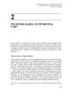
Figure 1-9: Resource model with distributed application
The function blocks of IEC 61499 resp. the automation objects (functions) of PROFInet are the
“atomic” elements, i.e. the not more divisible base elements, which are used for the engineering view
and as the run time objects. They consists in a body containing the executable algorithms and they
have interconnectable external interfaces for input and output data. Furthermore the function blocks
resp. the automation objects obtain a new kind of interface which is not existing for the function blocks
of the PLC standard IEC 61131-3.
The graphical editor Simatic iMap for PROFInet enables the project engineer to pick the automation
objects from a library and places them in his chart on the screen. Then the object types obtain their
project specific names and become instances. Afterwards the interfaces of the instances are con-
nected by the graphically drawing of lines between the input and outputs. Thus the communication
links over the bus are implicitly projected.
The automation solutions with technological modules typically have a fixed association between the
devices (resources) and the function blocks resp. automation objects, i.e. the associations are inher-
ently existing in the library elements. Therefore it is possible to load automatically the communication
information and the instances without any additional engineering. This loading is of course only nec-
essary if the instances are not yet pre-programmed or loaded earlier into the device. The devices with
in the firmware implemented functionality are only loaded with the preset values and the communica-
tion information for the interconnections.
Data flow
Event flow
Figure 1-10: Application model with interconnections of data and events
For a concise structuring of a larger application IEC 61499 defines the subapplication containing a
subset of interconnected function blocks. This subapplication may span also over multiple devices.
For PROFInet such a construct is also possible.
1.6.2.3 Extensions and differences
The differences of PROFInet and IEC 61499 can be divided in two categories. The first category of
differences are necessary to make the basis model of IEC 61499 more exact and clearer, or the fea-
tures exceed the given of the IEC model. The second category (see 1.6.2.3) is not discussed in this
specification because these extensions are not in the current and also future scope of IEC 61499.
PROFInet Architecture Description, Objects in Automation Version V2.0, January 2003
© Copyright by PNO 2003 - All rights reserved. Page 1-16
1.6.2.4 Mapping of the technological modularization
It is an important principle of the PROFInet concept not to define any internal details of the automation
components. This “inner live” shall not be influenced by PROFInet. The internal realization can be in
the case of a PLC a task model with function blocks according IEC 61131-3 in the case of other de-
vices it can be a functionality programmed in C language. The idea is to adopt the internal implemen-
tation of the functionality of the automation component as it stands.
PROFIBUS
Vendor A
Parameterization
Fieldbus X
Vendor C
Programming
Configuration
Parameterization
Programming
Configuration
Parameterization
PROFIBUS
Vendor B
PROFInet Connection Editor
Configuration
Programming
Vendor specific
Vendor specific
Vendor specific
Vendor independent
Figure 1-11: Manufacturer spanning engineering
The same principle is also applicable for the corresponding engineering tools, i.e. the programming,
configuring and parameterization of a device like a PLC can be achieved with the today available en-
gineering tools which are mostly IEC 61131-3 conformant programming systems like Simatic Step 7.
Therefore PROFInet defines exclusively the external interface of the components and not the internal
realization. Such an encapsulation of the functionality supports directly automation solutions with tech-
nological modularization, since for the interaction of the modules only the external interfaces are sig-
nificant and not the internal implementation.
IEC 61499 permits in principle such an encapsulation of the algorithms, however in the current PAS it
is not especially emphasized.
For the mapping of PROFInet the various characteristics of the term function block in IEC 61499 have
also be taken into account (Figure 1-12).
Function block
(generic term)
Function bloc
k
(Execution control +
IEC 61131 –3)
Service Interface
Function Block (SIFB)
(generic term for incapsulated FBs)
Service interface
Function Block (SIFB)
(incapsulated application FB)
Service Interface
Function Block (SIFB)
(Driver FB)
Figure 1-12: Various characteristics of the IEC 61499 functions blocks
• Function block (FB):
On the one hand this term is used by IEC 61499 as the generic term for all kinds of blocks on the
PROFInet Architecture Description, Objects in Automation Version V2.0, January 2003
© Copyright by PNO 2003 - All rights reserved. Page 1-17
other hand it is used for a specific characteristic of a function block where the internals are defined
by the Event Control Chart (ECC) for the execution control and by an IEC 61131-3 programming
language for the control algorithms (Figure 1-13
). Here the incoming events provoke correspond-
ing state transitions of the execution control, which activate the algorithms programmed in IEC
61131-3 and sends outgoing events when appropriate. For these function blocks also the internal
model of execution and programming is defined by IEC 61499.
Algorithms
(hidden)
Internal Data
(hidden)
Execution control
(hidden)
Data flow
Event flow
State diagram,
Event Control Chart
Programming and
data declaration according
IEC 61131-3
Figure 1-13: Function block according IEC 61499
As described above PROFInet does not make any provisions about the internal implementation,
thus the implementation with execution control and IEC 61131 are also permitted, however this
does not have any particular position.
• Service Interface Function Blocks (SIFB):
This IEC 61499 term identifies function blocks whose internal implementation is unknown. There
is no distinction between SIFB which encapsulate application programs and those who act as
“driver blocks” e.g. as interface to the controlled process.
The application oriented SIFB are equivalent to the automation objects (functions) of PROFInet.
However the “Driver SIFB“ are not part of PROFInet, because they belong to the internal realiza-
tion.
For the ability of the mapping of IEC 61499 onto the technological modularization the specification of
the internal realization of a function block with the execution control and the IEC 61131 programming
is not required. This applies also to the definition of “driver SIFB”. Such specifications of internals
should not be part of the mandatory set of the standard, but shall be defined in an optional part of the
specification.
1.6.2.5 Interconnections among the blocks (functions)
The interconnection between function blocks - in PROFInet called functions - is accomplished in IEC
61499 by events and data. Here the event is relevant, i.e. when a new event arrives an internal algo-
rithms is invoked. Data may be combined with the event. This is graphically represented by a line and
some connection points, however this graphic is only for illustration purpose and not imperatively re-
quired by the standard like all other graphical representations.
The combination of event with data can be made on the input and the output side, and therefore dif-
ferent variants are possible. Typically an event from the output side and the associated data of an IEC
function block are combined and connected with another IEC function block on its input side. At the
receiver side the event and the associated data are combined as well (Figure1-14a). Further variants
are illustrated in Figure 1-14 b, c, d.
PROFInet Architecture Description, Objects in Automation Version V2.0, January 2003
© Copyright by PNO 2003 - All rights reserved. Page 1-18
Events
data
a)
b)
c)
d)
Figure 1-14: Combinations of events with data
PROFInet restricts the degree of freedom for the combination of events and data (Figure 1-15).
Events
Data
Event with data
f
p1
p2
g
q1
q2
f(p1, p2)
g(q1, q2)
IEC 61499 PROFIne
t
Figure 1-15: PROFInet supports events with data
For PROFInet an event always has a set of parameters which has to match on the sender and re-
ceiver side. The parameters (data) of the event do not have to be available as individually handled
pieces of information at the external interface of the function. This restriction was done as a simplifica-
tion for the project engineer since the mentioned degree of freedom offered by IEC 61499 is required
only in very few application cases.
Another extension in PROFInet is the interconnection of data without an event. (Figure 1-16).
PROFInet Architecture Description, Objects in Automation Version V2.0, January 2003
© Copyright by PNO 2003 - All rights reserved. Page 1-19
Figure 1-16: Data interconnections
Data connection between function blocks are a well established concept defined by IEC 61131-3.
PROFInet extends this concept in a device spanning aspect. This facilitates the stepwise introduction
of a new concept since it extends the already existing paradigm “data connection” and it offers the
new paradigm “event connection” as an option.
1.6.2.6 Mapping of the communication
IEC 61499 typically presumes an IEC 61131 function block model in the devices. Therefore specific
communication function blocks have to be utilized for the implementation of the device spanning inter-
connections on the sender and receiver side (Figure 1-17). The installation of communication function
blocks can be done explicitly by the user or automatically by the engineering tool. The details of the
communication are not element of the normative part of IEC 61499, since they should be specified by
other standardization bodies or user organizations. For this purpose IEC 61499 supplies application
examples in the annex.
Mounting of
communication
function blocks
Publish
Subscribe
Figure 1-17: Communication function block with IEC 61499
PROFInet Architecture Description, Objects in Automation Version V2.0, January 2003
© Copyright by PNO 2003 - All rights reserved. Page 1-20
PROFInet takes a slightly different approach. As explained above PROFInet does not make any pro-
visions about the internal realization within the devices, i.e. it does not presumes a specific block
model. However PROFInet defines a run time model whose external interface is implemented by all
devices. (Figure 1-18)
Physical
Device
1
*
Logical Device
1
*
RT-Auto
1
1
ACCO
Logical Device
(=Software)
Physical Device
(=Hardware)
Figure 1-18: Class diagram of PROFInet
An important element of the run time model is the ACCO object (Active Control Connection Object).
This object implements a consumer-provider model at run time for the interconnections, i.e. the device
spanning communication relations specified in the engineering can be directly loaded into the devices.
For these interconnections PROFInet also defines the behavior in the error case:
• Additional transmission of validity information (quality code) and optional time stamp with values
• Output of substitute values in error case
• Monitoring of the communication partner
• Restart after loss of connection
• Ability of diagnosis and test for interconnections
Consequently the specifications of PROFInet substantiate the generic model of the interconnections of
the IEC 61499 function blocks. These specifications are required to embrace the practice in term of
interoperability of devices in a distributed automation solution.
1.6.2.7 Extensions of PROFInet exceeding the scope of IEC 61499
The PROFInet specification comprises also some areas exceeding the scope of IEC 61499. From
PROFInet view they are necessary for a comprehensive concept of distributed automation. They
should be briefly listed here:
• Engineering of the network topology, in particular multiple network types, e.g. PROFIBUS and
Ethernet
• Proxy model, i.e. inclusion of the existing bus systems without change of the protocol or the de-
vice
• Real time communication
• Manufacturer specific supplementations of the engineering for parameters, diagnosis etc.
• Support of technological components containing also elements of HMI or documentation besides
the control elements.
Further supplements like e.g. network management and web integration are already incorporated in
the planning of the PNO working groups.
PROFInet Architecture Description, Runtime Model Version V2.02 – February 2
nd
, 2004
© Copyright by PNO 2004 - All rights reserved. Page 2-1
Chapter 2: PROFInet Runtime Model
PROFInet Architecture Description, Runtime Model Version V2.02 – February 2
nd
, 2004
© Copyright by PNO 2004 - All rights reserved. Page 2-2
Contents
2 PROFINET RUNTIME MODEL 2-15
2.1 COM TERMS 2-15
2.1.1 Interface and Implementation 2-15
2.1.2 Properties 2-15
2.1.3 Methods 2-16
2.1.4 Events 2-16
2.1.5 Dispatch Interface 2-16
2.1.6 Communication Paths and Marshaling 2-16
2.1.7 IUnknown 2-17
2.1.7.1 Resource Management: IUnknown::AddRef, IUnknown::Release 2-18
2.1.7.2 Type Coercion: IUnknown::QueryInterface 2-18
2.1.8 Inheritance 2-18
2.2 RUNTIME OBJECT MODEL 2-19
2.2.1 Object Illusion 2-21
2.2.2 Basic Rules for Interface Definitions 2-22
2.2.3 Visual Basic Deficits 2-22
2.2.3.1 Using Automation Data Types 2-22
2.2.3.2 S-Codes as Return Values 2-24
2.2.3.3 Automation Wrapper 2-24
2.2.4 Instantiation of PROFInet Runtime Objects 2-25
2.2.5 Navigation in the Object Model 2-26
2.2.6 Life Cycle of PROFInet Runtime Objects 2-26
2.2.7 Definitions for the IDispatch Implementation 2-27
2.2.8 Definitions for Identifiers 2-27
2.2.8.1 Character Set Type 1 2-27
2.2.8.2 Character Set Type 2 2-28
2.2.8.3 Character Set Type 3 2-28
2.2.8.4 Common Definitions 2-28
2.2.8.5 Definitions for Domain Names 2-29
2.2.8.6 Usage of Character Sets 2-29
2.2.9 Definitions for Event Interfaces 2-29
2.2.10 Definitions for Properties 2-30
2.2.11 Extended Type Description 2-30
2.2.12 Additional Definitions for Structures 2-31
2.2.13 Security Aspects of PROFInet Runtime Components 2-32
2.2.13.1 COM Activation Security 2-33
2.2.13.2 COM Call Security 2-33
2.2.13.2.1 Explicit Call to CoInitializeSecurity 2-33
2.2.13.2.2 Implicit Call to CoInitializeSecurity 2-33
2.2.13.2.3 Visual Basic and Call Security 2-34
2.2.13.2.4 Scripts and Call Security 2-34
2.2.13.3 PROFInet Security Model 2-34
2.2.14 Interaction with Windows Systems 2-34
2.2.15 Optimizing Network Performance 2-35
2.2.16 Script Integration without Installation 2-37
2.2.17 Plug & Play 2-37
2.2.18 Baptism 2-37
2.2.19 Handling the Runtime Object Model 2-37
2.2.20 Supplying PROFInet Proxy Stub and PC PDev Software 2-38
2.2.21 Component Description and Type Library 2-39
2.3 INCLUDING NON–PROFINET COMPONENTS 2-40
2.4 INTERFACES OF THE RUNTIME COMPONENTS 2-43
2.5 IDENTIFICATION AND NAVIGATION 2-46
2.6 OPERATING STATE 2-47
2.6.1 ICBAStateEvent – Operating State Messages 2-48
2.7 DATE AND TIME 2-50
2.8 DIAGNOSIS 2-51
2.8.1 Motivation 2-51
PROFInet Architecture Description, Runtime Model Version V2.02 – February 2
nd
, 2004
© Copyright by PNO 2004 - All rights reserved. Page 2-3
2.8.2
User Perspective 2-52
2.8.3 Diagnosis Interface 2-53
2.8.4 Common Diagnosis 2-54
2.8.5 Detailed Diagnosis 2-55
2.8.6 Proprietary Diagnosis 2-57
2.8.7 Typical Device Faults 2-57
2.8.8 Monitoring 2-58
2.9 REPORTING 2-58
2.10 PARAMETER VALUE ASSIGNMENT 2-58
2.11 UPLOAD AND DOWNLOAD 2-59
2.12 ON-LINE / OFF-LINE COMPARISON 2-60
2.12.1 PDev Stamp 2-60
2.12.2 ACCO Stamp 2-61
2.12.3 LDev Stamp 2-61
2.12.4 Code / Configuration Data Stamp 2-61
2.13 INTERCONNECTING RTAUTOS – CBAACCO 2-63
2.13.1 Motivation 2-63
2.13.2 Architecture 2-64
2.13.3 Short Overview 2-65
2.13.3.1 Establishing connections 2-65
2.13.3.2 Productive Operation of Data Connections 2-66
2.13.3.3 Productive Operation of Event Connections 2-67
2.13.4 Definitions 2-67
2.13.4.1 Configuration Data Base 2-67
2.13.4.2 Rules for Connections 2-68
2.13.4.3 Definition of the Identifiers 2-69
2.13.4.3.1 Identifier for an LDev 2-69
2.13.4.3.2 Identifier for an RTAuto Member 2-69
2.13.4.3.3 Identifier for a System Member 2-70
2.13.4.3.4 Identifiers for accessing Sub elements 2-71
2.13.4.4 Data Types 2-73
2.13.4.5 Quality of Service (QoS) 2-75
2.13.4.6 Dead Band and Epsilon Value 2-77
2.13.4.7 Version of a connection 2-79
2.13.4.8 Substitute Values 2-79
2.13.4.9 Quality Code 2-80
2.13.4.9.1 Definitions in PROFInet 2-80
2.13.4.9.2 Standard Behavior 2-82
2.13.4.9.3 Startup of a Connection 2-83
2.13.4.9.4 Communication Fault of a Connection 2-83
2.13.4.9.5 Connection is cleared 2-84
2.13.4.9.6 Connection is deactivated 2-84
2.13.4.9.7 Transfer of „Incorrect” Connection Data 2-84
2.13.4.9.8 Provider in „CBAReady” State 2-85
2.13.4.9.9 Clearing an Object from the Provider 2-86
2.13.4.9.10 Connection is forced 2-86
2.13.4.9.11 QoS Violation 2-87
2.13.4.9.12 Write Access to Values via PropertyPut or WriteItem 2-87
2.13.4.9.13 Encoding the Quality Code 2-87
2.13.4.9.14 Component-Overlapping Quality Code 2-90
2.13.4.9.15 Property Access and Quality Code 2-91
2.13.4.9.16 OPC Server and Quality Code (OPC Quality flags) 2-92
2.13.4.10 Operating state 2-93
2.13.4.11 Power-On 2-93
2.13.4.12 Persistence 2-94
2.13.4.13 Online–/Offline Comparison of the Connections 2-96
2.13.5 Communication Channels 2-97
2.13.5.1 Configuration 2-97
2.13.5.2 DCOM 2-97
2.13.5.2.1 Context Management 2-97
PROFInet Architecture Description, Runtime Model Version V2.02 – February 2
nd
, 2004
© Copyright by PNO 2004 - All rights reserved. Page 2-4
2.13.5.2.2
QoS 2-98
2.13.5.2.3 QoS Violation 2-98
2.13.5.2.4 Connection Monitoring 2-99
2.13.5.2.4.1 Connection Monitoring by the Consumer 2-99
2.13.5.2.4.2 Connection Monitoring by the Provider 2-100
2.13.5.2.5 UML Model 2-100
2.13.5.3 SRT 2-100
2.13.5.3.1 Definitions 2-100
2.13.5.3.2 Application Relations and Communication Relations 2-101
2.13.5.3.3 Using SRT 2-103
2.13.5.3.3.1 SRT Variants 2-103
2.13.5.3.3.2 Segmentation 2-103
2.13.5.3.3.3 SRT Cycle Time and QoS Value 2-103
2.13.5.3.3.4 QoS Violation 2-104
2.13.5.3.3.5 Connection Monitoring 2-104
2.13.5.3.3.5.1 Connection Monitoring by the Consumer 2-104
2.13.5.3.3.5.2 Connection Monitoring by the Provider 2-105
2.13.5.3.3.6 IP Address and MAC Address 2-106
2.13.5.3.4 UML Model 2-108
2.13.5.3.4.1 Remote Interactions 2-108
2.13.5.3.4.2 State Machine for Application Relations 2-108
2.13.5.3.4.2.1 Consumer 2-110
2.13.5.3.4.2.2 Provider 2-111
2.13.5.3.4.3 State Machine for AccoDataCR 2-111
2.13.5.3.4.3.1 Consumer 2-112
2.13.5.3.4.3.2 Provider 2-112
2.13.5.3.4.3.3 Establishing the AccoDataCR 2-113
2.13.5.4 Local 2-114
2.13.5.4.1 QoS 2-115
2.13.5.4.2 QoS Violation 2-116
2.13.5.5 Constant 2-116
2.13.6 ACCO Management Operation 2-116
2.13.6.1 Overview 2-116
2.13.6.1.1 Tasks of the Consumer 2-116
2.13.6.1.2 Tasks of the Provider 2-116
2.13.6.2 Establishing Connections 2-117
2.13.6.2.1 Connections with a Constant 2-117
2.13.6.2.2 Negotiating with the Provider – Common Definitions 2-118
2.13.6.2.2.1 Connect Attempt 2-119
2.13.6.2.2.2 Signature Identity Check 2-120
2.13.6.2.2.2.1 Signature Identity Check for Data Connections (PROFInet Version 1)2-120
2.13.6.2.2.2.2 Signature Identity Check for Data Connections (PROFInet Version 2)2-121
2.13.6.2.2.2.3 Signature Identity Check for Event Connections 2-121
2.13.6.2.3 Negotiating with the Provider – DCOM 2-121
2.13.6.2.4 Negotiating with the Provider – SRT 2-122
2.13.6.2.4.1 Reconfiguration 2-123
2.13.6.2.4.1.1 Motivation 2-123
2.13.6.2.4.1.2 Algorithm 2-123
2.13.6.2.5 Negotiating with the Provider – Local 2-123
2.13.6.2.6 Negotiating with the Provider – Constant 2-124
2.13.6.3 Changing Connections 2-124
2.13.6.4 Clearing Connections 2-124
2.13.6.4.1 Negotiating with the Provider – DCOM 2-124
2.13.6.4.2 Negotiating with the Provider – SRT 2-124
2.13.6.4.3 Negotiating with the Provider – Local 2-124
2.13.6.4.4 Negotiating with the Provider – Constant 2-125
2.13.6.5 Activating and Deactivating Connections 2-125
2.13.6.5.1 Negotiating with the Provider – DCOM 2-125
2.13.6.5.2 Negotiating with the Provider – SRT 2-125
2.13.6.5.3 Negotiating with the Provider – Local 2-125
PROFInet Architecture Description, Runtime Model Version V2.02 – February 2
nd
, 2004
© Copyright by PNO 2004 - All rights reserved. Page 2-5
2.13.6.5.4
Negotiating with the Provider – Constant 2-126
2.13.7 Productive Operations of Connections 2-126
2.13.7.1 Productive Operation for Data Connections 2-126
2.13.7.1.1 DCOM Channel 2-126
2.13.7.1.2 SRT Channel 2-127
2.13.7.1.3 Local Channel 2-128
2.13.7.2 Productive Operation for Event Connections 2-128
2.13.7.3 Format for Connection Data 2-129
2.13.7.3.1 DCOM Channel Item Header 2-129
2.13.7.3.2 SRT Channel Item Header 2-130
2.13.7.3.3 Data 2-130
2.13.7.3.4 Serialization of Values and Parameters 2-131
2.13.7.3.4.1 Restrictions for the DCOM channel 2-131
2.13.7.3.4.2 Restrictions for the SRT channel 2-132
2.13.7.3.5 Serialization of Time Stamps 2-132
2.13.7.3.6 DCOM Peculiarities 2-133
2.13.7.3.7 SRT Peculiarities 2-133
2.13.7.4 Productive Operation (SRT) 2-134
2.13.7.5 Fault Scenarios 2-134
2.13.7.5.1 Error Classification 2-134
2.13.7.5.2 Time Intervals 2-136
2.13.7.5.3 Packet Duplication 2-136
2.13.7.5.4 Packet Loss 2-136
2.13.7.5.5 Garbled Data 2-136
2.13.7.5.6 Sequence Switching 2-136
2.13.7.5.7 Recycling Frames 2-137
2.13.7.5.8 Failure of the Provider in Productive Operation 2-137
2.13.7.5.8.1 DCOM Communication Channel 2-137
2.13.7.5.8.2 SRT Communication Channel 2-138
2.13.7.5.9 Failure of the Consumer in Productive Operation 2-140
2.13.7.5.9.1 DCOM Communication Channel 2-140
2.13.7.5.9.2 SRT Communication Channel 2-141
2.13.7.5.10 Unilateral Communication Failure Recognition during Productive Operation2-142
2.13.7.5.10.1 DCOM Communication Channel 2-142
2.13.7.5.10.2 SRT Communication Channel 2-142
2.13.7.5.11 Failure of the Provider during Negotiation 2-143
2.13.7.5.12 Transmission of Garbled Data 2-144
2.13.8 Connection Diagnosis 2-144
2.13.8.1 User Perspective 2-144
2.13.8.2 Status Model for the Common Diagnosis 2-145
2.13.8.3 Status Model for the Detailed Diagnosis 2-146
2.13.8.4 Diagnosis Information from the Consumer 2-149
2.13.8.5 Diagnosis Information from the Provider 2-149
2.13.8.6 GetDiagnosis Method 2-149
2.13.8.6.1 Common Definitions 2-149
2.13.8.6.2 Function 0: PROFInet Function Directory 2-150
2.13.8.6.3 Function 0x1000: Performance Characteristics 2-150
2.13.8.6.4 Function 0x2000: Statistics Reset 2-151
2.13.8.6.5 Function 0x3000: Consumer Communication Events Statistic 2-151
2.13.8.6.6 Function 0x4000: Provider Communication Events Statistic 2-152
2.13.8.7 Outside View 2-152
2.13.8.8 Inside View 2-152
2.13.8.9 Influencing Testing 2-152
2.13.8.9.1 Forcing 2-152
2.13.9 Synchronous Read / Write 2-154
2.13.9.1 Synchronous Access 2-154
2.13.10 HMI and ACCO 2-154
2.14 OPERATORS 2-155
2.14.1 Motivation 2-155
2.14.2 Operators to Data Connections 2-155
PROFInet Architecture Description, Runtime Model Version V2.02 – February 2
nd
, 2004
© Copyright by PNO 2004 - All rights reserved. Page 2-6
2.14.3
Operators to Event Connections 2-156
2.15 APPLICATION FUNCTIONALITY – RTAUTO 2-157
2.15.1 Possible Implementation Methods 2-158
2.15.1.1 Fixed Functionality 2-158
2.15.1.2 Loadable Functionality 2-158
2.15.2 Implementation of the Property Access Functions 2-160
2.15.3 Event Functionality 2-163
2.16 INTEGRATION OF PROFIBUS DP-SLAVES 2-164
2.16.1 Motivation 2-164
2.16.1.1 Object World and Station Failure 2-166
2.16.2 Tasks of the Proxy 2-167
2.16.3 Views 2-167
2.16.4 Decoupling Host and Componentized Slave 2-168
2.16.5 Proxy for LDev 2-169
2.16.5.1 Identification and Browse 2-169
2.16.5.2 Diagnosis 2-170
2.16.5.3 Operating State 2-170
2.16.5.4 Interface Implementation 2-171
2.16.5.5 Limitations for Programmable DP Slaves 2-172
2.16.6 Proxy for an RTAuto 2-172
2.16.6.1 Property Access 2-173
2.16.6.1.1 Property Access and Station Failure 2-174
2.16.6.1.2 Property Access and Pulled Modules 2-175
2.16.6.1.3 Property Access and DP Master in CLEAR State 2-175
2.16.6.1.4 Overview 2-177
2.16.6.2 DP Mapping 2-179
2.16.6.2.1 View of the DP Master 2-179
2.16.6.3 View of the DP Slave 2-179
2.16.6.3.1 Simple DP Slaves of a Fixed Functionality 2-180
2.16.6.3.2 Complex DP Slaves of a Fixed Functionality 2-181
2.16.6.3.3 Programmable DP Slaves 2-181
2.16.6.4 PROFIBUS Data Types vs. Automation Data Types 2-181
2.16.7 Proxy for ACCO 2-183
2.16.8 Open Points 2-183
2.16.8.1 DPV1 Integration 2-183
2.16.8.1.1 Data Records 2-183
2.16.8.1.2 Alarms 2-184
2.16.8.2 DPV2 Integration 2-184
2.16.8.3 PROFInet Master Profile 2-184
2.16.8.4 Lateral Communication 2-184
2.17 SYSTEM RTAUTO 2-185
2.17.1 Motivation 2-185
2.17.2 Requirements 2-185
2.17.3 Engineering View 2-185
2.18 PERFORMANCE CHARACTERISTICS 2-186
2.18.1 Motivation 2-186
2.18.2 Assurances 2-186
2.18.2.1 Constant, Local and SRT Connections 2-186
2.18.2.2 DCOM Connections 2-187
2.18.3 Device Parameters 2-187
2.18.4 ES / RT Parameter Set 2-189
2.18.4.1 Overview 2-189
2.18.4.2 General Parameters 2-189
2.18.4.3 Connection Relations 2-190
2.18.4.4 Communication Channels 2-195
2.18.4.4.1 General Definitions 2-195
2.18.4.4.2 Property Size 2-195
2.18.4.4.3 SRT Frame Costs according to Data Type 2-196
2.18.4.5 Constant Channel 2-196
2.18.4.6 Local Channel 2-197
PROFInet Architecture Description, Runtime Model Version V2.02 – February 2
nd
, 2004
© Copyright by PNO 2004 - All rights reserved. Page 2-7
2.18.4.7
SRT Channel 2-198
2.18.4.8 DCOM Channel 2-201
2.18.4.9 DCOM HMI Connections Parameter 2-203
2.18.4.10 DCOM Status Connection Parameters 2-203
2.18.4.11 Further Device Parameters 2-204
2.18.5 Assessment of RT Parameter Set in Version 2.0 2-204
2.18.6 Rules for ES systems 2-205
2.18.6.1 Client Best Practice Patterns 2-205
2.18.6.2 Timeouts for method calls 2-205
2.19 CLASSES 2-207
2.19.1 CBAPhysicalDevice 2-207
2.19.2 CBALogicalDevice 2-207
2.19.3 CBAACCO 2-207
2.19.4 RTAuto 2-207
2.20 INTERFACE DESCRIPTIONS 2-208
2.20.1 ICBAPhysicalDevice 2-208
2.20.1.1 ICBAPhysicalDevice::get_Producer 2-208
2.20.1.2 ICBAPhysicalDevice::get_Product 2-209
2.20.1.3 ICBAPhysicalDevice::get_SerialNo 2-209
2.20.1.4 ICBAPhysicalDevice::get_ProductionDate 2-210
2.20.1.5 ICBAPhysicalDevice::Revision 2-211
2.20.1.6 ICBAPhysicalDevice::get_LogicalDevice 2-211
2.20.2 ICBAPhysicalDevice2 2-213
2.20.2.1 ICBAPhysicalDevice2::Type 2-213
2.20.2.2 ICBAPhysicalDevice2::PROFInetRevision 2-214
2.20.2.3 ICBAPhysicalDevice2::get_PDevStamp 2-215
2.20.3 ICBABrowse 2-216
2.20.3.1 ICBABrowse::get_Count 2-216
2.20.3.2 ICBABrowse::BrowseItems 2-217
2.20.4 ICBABrowse2 2-218
2.20.4.1 ICBABrowse2::get_Count2 2-218
2.20.4.2 ICBABrowse2::BrowseItems2 2-219
2.20.5 ICBAPersist 2-221
2.20.5.1 ICBAPersist::Save 2-221
2.20.6 ICBAPersist2 2-222
2.20.6.1 ICBAPersist2::Save2 2-222
2.20.7 ICBAPhysicalDevicePC 2-224
2.20.7.1 ICBAPhysicalDevicePC::AddLogicalDevice 2-224
2.20.7.2 ICBAPhysicalDevicePC::RemoveLogicalDevice 2-225
2.20.7.3 ICBAPhysicalDevicePC::AdvisePDevPC 2-225
2.20.7.4 ICBAPhysicalDevicePC::UnadvisePDevPC 2-226
2.20.8 ICBAPhysicalDevicePCEvent 2-227
2.20.8.1 ICBAPhysicalDevicePCEvent::OnLogicalDeviceAdded 2-227
2.20.8.2 ICBAPhysicalDevicePCEvent::OnLogicalDeviceRemoved 2-228
2.20.9 ICBALogicalDevice 2-229
2.20.9.1 ICBALogicalDevice::get_Name 2-229
2.20.9.2 ICBALogicalDevice::get_Producer 2-230
2.20.9.3 ICBALogicalDevice::get_Product 2-230
2.20.9.4 ICBALogicalDevice::get_SerialNo 2-231
2.20.9.5 ICBALogicalDevice::get_ProductionDate 2-232
2.20.9.6 ICBALogicalDevice::Revision 2-232
2.20.9.7 ICBALogicalDevice::get_ACCO 2-233
2.20.9.8 ICBALogicalDevice::get_RTAuto 2-233
2.20.10 ICBALogicalDevice2 2-234
2.20.10.1 ICBALogicalDevice2::PROFInetRevision 2-235
2.20.10.2 ICBALogicalDevice2::ComponentInfo 2-235
2.20.11 ICBAState 2-236
2.20.11.1 ICBAState::get_State 2-237
2.20.11.2 ICBAState::Activate 2-237
2.20.11.3 ICBAState::Deactivate 2-238
PROFInet Architecture Description, Runtime Model Version V2.02 – February 2
nd
, 2004
© Copyright by PNO 2004 - All rights reserved. Page 2-8
2.20.11.4
ICBAState::Reset 2-238
2.20.11.5 ICBAState::AdviseState 2-239
2.20.11.6 ICBAState::UnadviseState 2-239
2.20.12 ICBAStateEvent 2-241
2.20.12.1 ICBAStateEvent::OnStateChanged 2-241
2.20.13 ICBATime 2-242
2.20.13.1 ICBATime::get_Time 2-242
2.20.13.2 ICBATime::put_Time 2-243
2.20.14 ICBAGroupError 2-244
2.20.14.1 ICBAGroupError::GroupError 2-244
2.20.14.2 ICBAGroupError::AdviseGroupError 2-245
2.20.14.3 ICBAGroupError::UnadviseGroupError 2-246
2.20.15 ICBAGroupErrorEvent 2-247
2.20.15.1 ICBAGroupErrorEvent::OnGroupErrorChanged 2-247
2.20.16 ICBAAccoMgt 2-248
2.20.16.1 ICBAAccoMgt::AddConnections 2-248
2.20.16.2 ICBAAccoMgt::RemoveConnections 2-250
2.20.16.3 ICBAAccoMgt::ClearConnections 2-251
2.20.16.4 ICBAAccoMgt::SetActivationState 2-252
2.20.16.5 ICBAAccoMgt::GetInfo 2-253
2.20.16.6 ICBAAccoMgt::GetIDs 2-253
2.20.16.7 ICBAAccoMgt::GetConnections 2-254
2.20.16.8 ICBAAccoMgt::ReviseQoS 2-256
2.20.16.9 ICBAAccoMgt::get_PingFactor 2-256
2.20.16.10 ICBAAccoMgt::put_PingFactor 2-257
2.20.16.11 ICBAAccoMgt::get_CDBCookie 2-258
2.20.17 ICBAAccoMgt2 2-259
2.20.17.1 ICBAAccoMgt2::GetConsIDs 2-259
2.20.17.2 ICBAAccoMgt2::GetConsConnections 2-260
2.20.17.3 ICBAAccoMgt2::DiagConsConnections 2-261
2.20.17.4 ICBAAccoMgt2::GetProvIDs 2-262
2.20.17.5 ICBAAccoMgt2::GetProvConnections 2-263
2.20.17.6 ICBAAccoMgt2::GetDiagnosis 2-264
2.20.18 ICBAAccoCallback 2-266
2.20.18.1 ICBAAccoCallback::OnDataChanged 2-266
2.20.19 ICBAAccoCallback2 2-267
2.20.19.1 ICBAAccoCallback2::Gnip 2-267
2.20.20 ICBAAccoServer 2-268
2.20.20.1 ICBAAccoServer::Connect 2-268
2.20.20.2 ICBAAccoServer::Disconnect 2-270
2.20.20.3 ICBAAccoServer::DisconnectMe 2-271
2.20.20.4 ICBAAccoServer::SetActivation 2-271
2.20.20.5 ICBAAccoServer::Ping 2-272
2.20.21 ICBAAccoServer2 2-274
2.20.21.1 ICBAAccoServer2::Connect2 2-274
2.20.22 ICBAAccoServerSRT 2-277
2.20.22.1 ICBAAccoServerSRT::ConnectCR 2-277
2.20.22.2 ICBAAccoServerSRT::DisconnectCR 2-280
2.20.22.3 ICBAAccoServerSRT::Connect 2-280
2.20.22.4 ICBAAccoServerSRT::Disconnect 2-282
2.20.22.5 ICBAAccoServerSRT::DisconnectMe 2-283
2.20.22.6 ICBAAccoServerSRT::SetActivation 2-284
2.20.23 ICBAAccoSync 2-285
2.20.23.1 ICBAAccoSync::ReadItems 2-285
2.20.23.2 ICBAAccoSync::WriteItems 2-286
2.20.23.3 ICBAAccoSync::WriteItemsQCD 2-288
2.20.24 ICBARTAuto 2-290
2.20.24.1 ICBARTAuto::get_Name 2-290
2.20.24.2 ICBARTAuto::Revision 2-291
2.20.25 ICBARTAuto2 2-292
PROFInet Architecture Description, Runtime Model Version V2.02 – February 2
nd
, 2004
© Copyright by PNO 2004 - All rights reserved. Page 2-9
2.20.25.1
ICBARTAuto2::ComponentInfo 2-292
2.20.26 ICBASystemProperties 2-294
2.20.26.1 ICBASystemProperties::get_StateCollection 2-294
2.20.26.2 ICBASystemProperties::get_StampCollection 2-295
2.20.27 PROFInet Runtime IDL Specification 2-296
2.20.27.1 Basic Information 2-296
2.20.27.2 Error Messages 2-297
2.20.27.3 Interface Definitions for the PROFInet Device 2-309
PROFInet Architecture Description, Runtime Model Version V2.02 – February 2
nd
, 2004
© Copyright by PNO 2004 - All rights reserved. Page 2-10
Figures
Figure 2-1: InProc call 2-17
Figure 2-2: InterProc or Remote call 2-17
Figure 2-3: Runtime object model 2-19
Figure 2-4: Relationship between Engineering and Runtime 2-20
Figure 2-5: Automation Wrapper 2-25
Figure 2-6: Navigation in the runtime object model 2-26
Figure 2-7: Inclusion of non-PROFInet devices 2-41
Figure 2-8: Interfaces 2-43
Figure 2-9: Operating state block diagram 2-47
Figure 2-10: Typical operating state block diagram with sub-states 2-48
Figure 2-11: On-line view of the device diagram 2-53
Figure 2-12: Diagnosis procedure 2-53
Figure 2-13: Information levels 2-54
Figure 2-14: Device status model for the common diagnosis 2-54
Figure 2-15: Events in common diagnosis 2-55
Figure 2-16: Convenience information (brief information) for the device 2-56
Figure 2-17: Convenience information (long information) for the device 2-57
Figure 2-18: Possible User Perspective 2-63
Figure 2-19: Consumer and provider of a connection 2-64
Figure 2-20: ACCO structure 2-65
Figure 2-21: Productive operation of data connections 2-66
Figure 2-22: Productive operation of event connections
15
2-67
Figure 2-23: Quality code transfer – standard behavior 2-82
Figure 2-24: Startup of a Connection 2-83
Figure 2-25: Quality code with communication fault 2-83
Figure 2-26: Quality code when a connection is cleared 2-84
Figure 2-27: Quality code when a connection is deactivated 2-84
Figure 2-28: Quality Code during the transfer of „incorrect” connection data 2-85
Figure 2-29: Quality code for provider in „CBAReady” state 2-86
Figure 2-30: Clearing an object from the provider 2-86
Figure 2-31: Quality code when a connection is forced 2-87
Figure 2-32: Quality Code at QoS violation 2-87
Figure 2-33: QoS and DCOM Communication Channel 2-98
Figure 2-34: Monitoring the providers heartbeat 2-99
Figure 2-35: Communication Stack for PROFInet Devices 2-101
Figure 2-36: Application Relations between PROFInet Devices 2-102
Figure 2-37: Communication Relations 2-102
Figure 2-38: Communication Channel SRT 2-104
Figure 2-39: Logical network view of PROFInet devices 2-106
Figure 2-40: DCOM and ACP Interaction between Provider and Consumer 2-108
Figure 2-41: State Machine AR
SRT
– Consumer 2-110
Figure 2-42: State Machine AR
SRT
– provider 2-111
Figure 2-43: State Machine AccoDataCR – Consumer 2-112
Figure 2-44: State Machine AccoDataCR – Provider 2-112
Figure 2-45: SRT Frame Layout 2-113
Figure 2-46: Establishing an AccoDataCR 2-114
Figure 2-47: Flowchart – Copy Cycle for Local Connections 2-115
PROFInet Architecture Description, Runtime Model Version V2.02 – February 2
nd
, 2004
© Copyright by PNO 2004 - All rights reserved. Page 2-11
Figure 2-48: State Machine Connect Attempt 2-119
Figure 2-49: Productive operation of data connections (DCOM) 2-126
Figure 2-50: Productive operation of data connections (SRT) 2-127
Figure 2-51: Productive operation of data connections (Local) 2-128
Figure 2-52: Productive operation of event connections
47
2-128
Figure 2-53: Format of the byte stream for connection data 2-129
Figure 2-54: SRT Frame 2-132
Figure 2-55: Data Flow for Cyclic SRT 2-134
Figure 2-56: Failure of the provider in productive operation (DCOM) 2-137
Figure 2-57: Scenario 1: Provider failure in productive operation (SRT) 2-139
Figure 2-58: Scenario 2: Recovery from provider failure in productive operation (SRT) 2-140
Figure 2-59: Failure of the consumer 2-141
Figure 2-60: Failure of the consumer 2-142
Figure 2-61: Failure of the provider when setting up connections 2-144
Figure 2-62: Information levels 2-145
Figure 2-63: ACCO status model for the common diagnosis 2-145
Figure 2-64: ACCO status model for the detailed diagnosis 2-146
Figure 2-65: Implementation of an RTAuto for IEC 61131-3 PLC 2-159
Figure 2-66: Modeling a PROFIBUS DP Proxy 2-165
Figure 2-67: Views 2-166
Figure 2-68: Views 2-167
Figure 2-69: Decoupling Host and Slave 2-169
Figure 2-70: Device status model for the common diagnosis regarding a DP slave 2-170
Figure 2-71: Correlation PROFInet view and DP view 2-173
Figure 2-72: Mapping the PROFInet view onto the application 2-179
Figure 2-73: Producing a process-related view onto a DP slave of a fixed functionality 2-180
Figure 2-74: Componer for DP slaves of a fixed functionality 2-181
Figure 2-75: Proxy for ACCO 2-183
Figure 2-76: Device Parameters in Engineering and Runtime 2-188
Figure 2-77: Remote ACCO and ACCO pair 2-191
Figure 2-78: Constant Connections 2-193
Figure 2-79: DCOM and SRT Connections 2-194
Figure 2-80: Interface and class definition diagram for PROFInet 2-296
PROFInet Architecture Description, Runtime Model Version V2.02 – February 2
nd
, 2004
© Copyright by PNO 2004 - All rights reserved. Page 2-12
Tables
Table 2-1: Using Automation Data Types in Visual Basic 2-23
Table 2-2: Usage of Character Sets 2-29
Table 2-3: Differences between Record and Structure 2-32
Table 2-4: Interfaces 2-45
Table 2-5: Date and time 2-50
Table 2-6: CRC32 Table 2-61
Table 2-7: Connectable data types 2-73
Table 2-8: Supported Data Types according to PROFInet Version 2-74
Table 2-9: QoS Subtypes in the DCOM Communication Channel 2-75
Table 2-10: QoS Type and QoS Value 2-77
Table 2-11: Epsilon value for connectable data types 2-78
Table 2-12: Quality Codes explicitly created and used by PROFInet 2-81
Table 2-13: Encoding the Quality Code – Overview 2-88
Table 2-14: Encoding the Quality Code – Limits 2-88
Table 2-15: Encoding the Quality Code – Bad 2-88
Table 2-16: Encoding the Quality Code – Uncertain 2-89
Table 2-17: Encoding the Quality Code – Good (Non Cascade) 2-89
Table 2-18: Encoding the Quality Code – Good (Cascade) 2-90
Table 2-19: Encoding the Quality Code – Invalid Quality Codes 2-90
Table 2-20: Quality Code priority table 2-91
Table 2-21: Mapping Quality Codes towards OPC 2-93
Table 2-22: Maximum DCOM Substitute Value Apply Time (shown in ms) 2-100
Table 2-23: Usage of SRT Variants 2-103
Table 2-24: Mapping QoS Value to SRT Cycle Time (shown in ms) 2-104
Table 2-25: Maximum SRT Substitute Value Apply Time (shown in ms) 2-105
Table 2-26: Transfer Format 2-129
Table 2-27: Header structure 2-129
Table 2-28: Structure of a connection data item (DCOM channel) 2-129
Table 2-29: Structure of a connection data item (SRT channel) 2-130
Table 2-30: Data connection data 2-130
Table 2-32: Data format for serialized connection data 2-131
Table 2-33: How to compute the Length of the SRT Reference Data 2-132
Table 2-34: HRESULT Structure 2-135
Table 2-35: HRESULT Classification 2-135
Table 2-36: Time Intervals and Timeouts 2-136
Table 2-37: Error codes for the ACCO detailed diagnosis 2-148
Table 2-38: ICBAAccoMgt2::GetDiagnosis Functions IDs 2-149
Table 2-39: Access to properties of an RTAuto and the appropriate HRESULT 2-161
Table 2-40: Access to properties of a “!SYSTEM” RTAuto and the appropriate HRESULT 2-161
Table 2-41: Common HRESULTs on Access to properties of an RTAuto 2-162
Table 2-42: Quality Codes for an RTAuto 2-162
Table 2-43: Quality Codes for a “!SYSTEM” RTAuto 2-162
Table 2-44: Mapping the PROFInet Runtime Object Model onto a PROFIBUS DP Slave 2-166
Table 2-45: Mapping the DP View onto the PROFInet View 2-168
Table 2-46: Implementation of the standard interfaces for a Proxy LDev 2-171
Table 2-47: Overview Operating State and Group Error for a Proxy LDev 2-172
Table 2-48: Implementation of the properties of an RTAuto 2-173
PROFInet Architecture Description, Runtime Model Version V2.02 – February 2
nd
, 2004
© Copyright by PNO 2004 - All rights reserved. Page 2-13
Table 2-49: Access to properties of a Proxy to a DP-Slave and appropriate HRESULT 2-177
Table 2-50: Access to system properties of a Proxy to a DP-Slave and appropriate HRESULT 2-177
Table 2-51: Common HRESULTs on Access to properties of an RTAuto 2-178
Table 2-52: Quality Codes for a Proxy to a DP-Slave 2-178
Table 2-53: Quality Codes for system properties of a Proxy to a DP-Slave 2-179
Table 2-54: PROFIBUS Data Types vs. Automation Data Types 2-182
Table 2-55: General Parameters 2-190
Table 2-56: Connection Parameters 2-190
Table 2-57: Property Size 2-195
Table 2-58: SRT Frame Costs 2-196
Table 2-59: Constant Connections Parameters 2-196
Table 2-60: Local Connection Parameters 2-197
Table 2-61: SRT Connections Parameters 2-198
Table 2-62: SRT Power Parameters 2-199
Table 2-63: DCOM Productive Data Connections Parameters 2-201
Table 2-64: DCOM Power Parameters 2-202
Table 2-65: DCOM HMI Connections Parameters 2-203
Table 2-66: DCOM Status Connections Parameters 2-204
Table 2-67: Further Device Parameters 2-204
Table 2-68: Timeouts for Method Calls 2-206
PROFInet Architecture Description, Runtime Model Version V2.02 – February 2
nd
, 2004
© Copyright by PNO 2004 - All rights reserved. Page 2-14
Changes
Changes compared to the last distributed Version of this paper are marked with a change bar. How-
ever editorial changes are not further marked.
Version Chapter Change
2.02 2.2.7 Clarification on exception and HRESULT
2.02
2.13.4.5 Status connections are only allowed to connect system variables. Al-
lowed QoS values for status connections reduced to 500 and 1000 ms.
2.02
2.13.4.9.8
2.13.4.9.15
Properties of a !SYSTEM RTAuto as provider remain valid in
“CBAReady”.
2.02
2.13.4.12 Persistence of SRT connections on no longer functional Ethernet inter-
face.
2.02
2.13 Maximum size of SRT reference data changed from 480 bytes to 484
bytes.
2.02
2.13.5.3.3.3 Maximum SRT cycle time reduced to 512 ms according to PROFInet IO
specification.
2.02
2.13.5.3.3.5.2
Gnip time interval changed to 10 seconds.
2.02
2.13.7.5.1
2.13.7.5.2
Added error classification and time intervals chapter for clarifications.
2.02
2.13.7.5.9.1 Added error correction on slow update.
2.02
2.13.7.5.10.2 Added error scenario, which is not detected by PROFInet Runtime
Source Version 2
2.02
2.13.8.3 Added station failure and link failure to table 2-37.
2.02
2.13.8.6.1 Added note for upward compatibility.
2.02
2.13.8.6.6 Added SrtDropCnt to CBA_Stats_ProviderEvents_t.
2.02
2.15.2 Added system properties to description.
2.02
2.16.5.4 Clarifications to interface implementation.
2.02
2.16.6 Added system properties to description.
2.02
2.18.4.3 Added CBA_CAT_CNT_OBSERVERS.
2.02
2.18.5 Updated computation since only one reconfiguration frame is needed in
PROFInet Runtime Source Version 2.
2.02
2.18.6.2 Changed Alive Timeout to 1500 ms.
2.02
2.20 Updated error returns
2.02
2.20.23.2 Updated behavior on access to sub elements.
2.02
2.20.26.1 Incompatible change to get_StateCollection.
2.02
2.20.27.2 Added CBA_E_LINKFAILURE
2.02
2.20.27.3 Incompatible change to get_StateCollection (only comment in this case).