Tài liệu Behavioral Modeling part 8 docx
Bạn đang xem bản rút gọn của tài liệu. Xem và tải ngay bản đầy đủ của tài liệu tại đây (28.78 KB, 8 trang )
[ Team LiB ]
7.9 Examples
In order to illustrate the use of behavioral constructs discussed earlier in this chapter, we
consider three examples in this section. The first two, 4-to-1 multiplexer and 4-bit
counter, are taken from Section 6.5
, Examples. Earlier, these circuits were designed by
using dataflow statements. We will model these circuits with behavioral statements. The
third example is a new example. We will design a traffic signal controller, using
behavioral constructs, and simulate it.
7.9.1 4-to-1 Multiplexer
We can define a 4-to-1 multiplexer with the behavioral case statement. This multiplexer
was defined, in Section 6.5.1
, 4-to-1 Multiplexer, by dataflow statements. It is described
in Example 7-35
by behavioral constructs. The behavioral multiplexer can be substituted
for the dataflow multiplexer; the simulation results will be identical.
Example 7-35 Behavioral 4-to-1 Multiplexer
// 4-to-1 multiplexer. Port list is taken exactly from
// the I/O diagram.
module mux4_to_1 (out, i0, i1, i2, i3, s1, s0);
// Port declarations from the I/O diagram
output out;
input i0, i1, i2, i3;
input s1, s0;
//output declared as register
reg out;
//recompute the signal out if any input signal changes.
//All input signals that cause a recomputation of out to
//occur must go into the always @( ) sensitivity list.
always @(s1 or s0 or i0 or i1 or i2 or i3)
begin
case ({s1, s0})
2'b00: out = i0;
2'b01: out = i1;
2'b10: out = i2;
2'b11: out = i3;
default: out = 1'bx;
endcase
end
endmodule
7.9.2 4-bit Counter
In Section 6.5.3
, Ripple Counter, we designed a 4-bit ripple carry counter. We will now
design the 4-bit counter by using behavioral statements. At dataflow or gate level, the
counter might be designed in hardware as ripple carry, synchronous counter, etc. But, at a
behavioral level, we work at a very high level of abstraction and do not care about the
underlying hardware implementation. We will design only functionality. The counter can
be designed by using behavioral constructs, as shown in Example 7-36
. Notice how
concise the behavioral counter description is compared to its dataflow counterpart. If we
substitute the counter in place of the dataflow counter, the simulation results will be
exactly the same, assuming that there are no x and z values on the inputs.
Example 7-36 Behavioral 4-bit Counter Description
//4-bit Binary counter
module counter(Q , clock, clear);
// I/O ports
output [3:0] Q;
input clock, clear;
//output defined as register
reg [3:0] Q;
always @( posedge clear or negedge clock)
begin
if (clear)
Q <= 4'd0; //Nonblocking assignments are recommended
//for creating sequential logic such as flipflops
else
Q <= Q + 1;// Modulo 16 is not necessary because Q is a
// 4-bit value and wraps around.
end
endmodule
7.9.3 Traffic Signal Controller
This example is fresh and has not been discussed before in the book. We will design a
traffic signal controller, using a finite state machine approach.
Specification
Consider a controller for traffic at the intersection of a main highway and a country road.
The following specifications must be considered:
• The traffic signal for the main highway gets highest priority because cars are
continuously present on the main highway. Thus, the main highway signal remains
green by default.
• Occasionally, cars from the country road arrive at the traffic signal. The traffic
signal for the country road must turn green only long enough to let the cars on the
country road go.
• As soon as there are no cars on the country road, the country road traffic signal
turns yellow and then red and the traffic signal on the main highway turns green
again.
• There is a sensor to detect cars waiting on the country road. The sensor sends a
signal X as input to the controller. X = 1 if there are cars on the country road;
otherwise, X= 0.
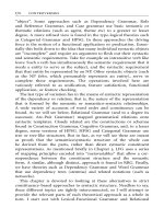
• There are delays on transitions from S1 to S2, from S2 to S3, and from S4 to S0.
The delays must be controllable.
The state machine diagram and the state definitions for the traffic signal controller are
shown in Figure 7-1
.
Figure 7-1. FSM for Traffic Signal Controller
Verilog description
The traffic signal controller module can be designed with behavioral Verilog constructs,
as shown in Example 7-37
.
Example 7-37 Traffic Signal Controller
`define TRUE 1'b1
`define FALSE 1'b0
//Delays
`define Y2RDELAY 3 //Yellow to red delay
`define R2GDELAY 2 //Red to green delay
module sig_control
(hwy, cntry, X, clock, clear);
//I/O ports
output [1:0] hwy, cntry;
//2-bit output for 3 states of signal
//GREEN, YELLOW, RED;
reg [1:0] hwy, cntry;
//declared output signals are registers
input X;
//if TRUE, indicates that there is car on
//the country road, otherwise FALSE
input clock, clear;
parameter RED = 2'd0,
YELLOW = 2'd1,
GREEN = 2'd2;
//State definition HWY CNTRY
parameter S0 = 3'd0, //GREEN RED
S1 = 3'd1, //YELLOW RED
S2 = 3'd2, //RED RED
S3 = 3'd3, //RED GREEN
S4 = 3'd4; //RED YELLOW
//Internal state variables
reg [2:0] state;
reg [2:0] next_state;
//state changes only at positive edge of clock
always @(posedge clock)
if (clear)
state <= S0; //Controller starts in S0 state
else
state <= next_state; //State change
//Compute values of main signal and country signal
always @(state)
begin
hwy = GREEN; //Default Light Assignment for Highway light
cntry = RED; //Default Light Assignment for Country light
case(state)
S0: ; // No change, use default
S1: hwy = YELLOW;
S2: hwy = RED;
S3: begin
hwy = RED;
cntry = GREEN;
end
S4: begin
hwy = RED;
cntry = `YELLOW;
end
endcase
end
//State machine using case statements
always @(state or X)
begin
case (state)
S0: if(X)
next_state = S1;
else
next_state = S0;
S1: begin //delay some positive edges of clock
repeat(`Y2RDELAY) @(posedge clock) ;
next_state = S2;
end
S2: begin //delay some positive edges of clock
repeat(`R2GDELAY) @(posedge clock);
next_state = S3;
end
S3: if(X)
next_state = S3;
else
next_state = S4;
S4: begin //delay some positive edges of clock
repeat(`Y2RDELAY) @(posedge clock) ;
next_state = S0;
end
default: next_state = S0;
endcase
end
endmodule
Stimulus
Stimulus can be applied to check if the traffic signal transitions correctly when cars arrive
on the country road. The stimulus file in Example 7-38
instantiates the traffic signal
controller and checks all possible states of the controller.
Example 7-38 Stimulus for Traffic Signal Controller
//Stimulus Module
module stimulus;
wire [1:0] MAIN_SIG, CNTRY_SIG;
reg CAR_ON_CNTRY_RD;
//if TRUE, indicates that there is car on
//the country road
reg CLOCK, CLEAR;
//Instantiate signal controller
sig_control SC(MAIN_SIG, CNTRY_SIG, CAR_ON_CNTRY_RD, CLOCK, CLEAR);
//Set up monitor
initial
$monitor($time, " Main Sig = %b Country Sig = %b Car_on_cntry = %b",
MAIN_SIG, CNTRY_SIG, CAR_ON_CNTRY_RD);
//Set up clock
initial
begin
CLOCK = `FALSE;
forever #5 CLOCK = ~CLOCK;
end
//control clear signal
initial
begin
CLEAR = `TRUE;
repeat (5) @(negedge CLOCK);
CLEAR = `FALSE;
end
//apply stimulus
initial
begin
CAR_ON_CNTRY_RD = `FALSE;
repeat(20)@(negedge CLOCK); CAR_ON_CNTRY_RD = `TRUE;
repeat(10)@(negedge CLOCK); CAR_ON_CNTRY_RD = `FALSE;
repeat(20)@(negedge CLOCK); CAR_ON_CNTRY_RD = `TRUE;
repeat(10)@(negedge CLOCK); CAR_ON_CNTRY_RD = `FALSE;
repeat(20)@(negedge CLOCK); CAR_ON_CNTRY_RD = `TRUE;
repeat(10)@(negedge CLOCK); CAR_ON_CNTRY_RD = `FALSE;
repeat(10)@(negedge CLOCK); $stop;
end
endmodule
N
ote that we designed only the behavior of the controller without worrying about how it
will be implemented in hardware.
[ Team LiB ]