Tài liệu Cảm biến trong sản xuất P4 docx
Bạn đang xem bản rút gọn của tài liệu. Xem và tải ngay bản đầy đủ của tài liệu tại đây (1.3 MB, 24 trang )
Sensors in production systems such as machine tools or robots may be classified
into four categories (Figure 2-1). They are activated either during operation or in
the set-up phase. Three types of sensors may be applied during the operation:
those which measure kinematic values such as position, velocity, orientation or an-
gular velocity, sensors which are applied to control the process in adaptive control
systems, and sensors which are used to monitor the production systems and to
provide diagnostic functions to assure a high availability of the systems. Sensors
for process control functions are shown in Chapters 3 and 4 and will not be men-
tioned here. Sensors which are applied in the set-up phase are used after assem-
bly to adjust or test the accuracy of the systems or to calibrate the interacting
members of the kinematic chain.
2.1
Position Measurement
In this section sensors are described which measure linear or rotational movements
mainly during operations of machine tools and robots. These sensors became of es-
47
2
Sensors for Machine Tools and Robots
H. K. Tönshoff, Universität Hannover, Hannover, Germany
Fig. 2-1 Sensors in production systems
Sensors in Manufacturing. Edited by H.K. Tönshoff, I. Inasaki
Copyright © 2001 Wiley-VCH Verlag GmbH
ISBNs: 3-527-29558-5 (Hardcover); 3-527-60002-7 (Electronic)
sential importance with the introduction of position control loops for numerical con-
trolled machines (Figure 2-2) [1]. The applied electric and in a few cases hydraulic or
pneumatic drives are not able to be positioned by themselves in a control chain but
need a feedback of a position signal. An exception to these control loop-based drives
are the digital controllable stepping motors. Their application is limited because of
accuracy, dynamics, and power. Thus every numerical controlled axis of a machine,
tool, or robot that means every feed movement needs at least one position sensor.
Since the feed movement in a machine tool, eg, the tool movement of a turning ma-
chine, determines the accuracy of the machine, properties of the sensors namely
their resolution, their repeatability, their drift velocity, and others (see Chapter 1.3)
are of fundamental importance for the accuracy of a production system.
A sensor can be set either directly or indirectly. Indirect means that the travel
or the position of a moved machine part such as a slide or a table of a machine
tool or the arm of a robot are not directly measured but by means of a move-
ment- transforming device (Figure 2-3).
2 Sensors for Machine Tools and Robots48
Fig. 2-2 Control loop in numerical controlled machine tools
Fig. 2-3 Placement of position sensors
This is normally a transformer from rotational to translatory movements for lin-
ear moving slides such as a ball screw (see Figure 2-2), a pinion-rack, a screw-
rack, a roll-band, or a wheel-track device. Strongly speed-reducing transmissions
such as harmonic drives, worm drives, and others are used for rotational moving
tables or arms. Because of the high speed reduction, the demands on the accu-
racy of a rotational sensor are much higher if it is placed behind the transformer
than before it. Indirect sensing in general has the advantage that there is no need
for cost-effective measuring devices so that simple and reliable seals can be used.
It has the disadvantage that errors of the transmission system are introduced in
the measured quantity. These can be, for instance, thermal or elastic deformations
of the ball screw or geometric and kinematical aberrations of the transmission
system in robots (Figure 2-4).
Therefore, the direct measuring principle should be used if high accuracy and
small aberrations are required, eg, for radial positioning in grinding or turning
machines. On the other hand, it has to be considered that indirect measurement
very often gives a better chance to follow Abbe’s principle in machine tools (Fig-
ure 2-5). This principle demands that the probe, in this case the travel of the ma-
2.1 Position Measurement 49
Fig. 2-4 Direct and indirect position measurement
Fig. 2-5 Abbe’s principle for machine tools
chine component, and the scale for measuring the travel be in alignment, other-
wise errors can occur by non-orthogonality and by tilting effects. It is possible to
reach the necessary alignment for indirect measuring systems approximately
whereas the direct measuring system is usually placed parallel to the slide and is
thus sensitive against tilting errors.
Sensors can be separated in accordance with the kind of signal into analog and
digital position-measuring devices. An example of an analog system is the voltage
divider (Figure 2-6). The sensor is applied for limited relative resolutions. It can
be based on a resistance wire or a vapor-deposited layer of carbon. The resistance
of this element is
R
b
q Á
l
A
2-1
where the specific resistance q and the cross section A of the conducting wire or
layer may be erroneous. In addition, the voltage U
x
has to be measured within
the tolerance of the resolution. For example, the technical limit can be assumed
to be 0.1 mV of a 10 V maximal voltage. That means a relative resolution of 10
–5
or a positional resolution of 1 lm limits the maximum travel to 100 mm.
The digital sensor determines the position either by counting increments (digi-
tal-incremental measurement) or by reading coded numbers (digital-absolute mea-
surement) (Figure 2-7). The resolution is given by the width of the incremental
unit. The length of measurement l and the incremental width s are connected by
l 2
n
s 2-2
where n is the number of bits necessary to describe the maximum length with a
resolution of s. For the example of s =1 lm and l= 250 mm,
n
log
À
l
s
Á
log 2
17:9 2-3
2 Sensors for Machine Tools and Robots50
Fig. 2-6 Potentiometric sensor
This means that 18 bits have to be implemented in the counter of an incremental
system or 18 channels have to be incorporated in an absolute system. The incre-
mental measurement has the disadvantage that the position can only be deter-
mined relatively. The digital absolute sensor, on the other hand, has the disadvan-
tage that the system needs a large number of channels for a long measuring
length and a high resolution and is therefore expensive. All three mentioned
kinds of measurement, the analog, the absolute-digital and the incremental-digital
principle, have their specific advantages. Therefore, the idea of combining favor-
able abilities is not unreasonable. This leads to the cyclic-absolute measuring prin-
ciple. It takes advantage of the absolute character of the analog system applying it
only on limited measuring lengths and of the incremental sensing principle with
its simple structure and robustness. It is shown schematically in Figure 2-8.
2.1 Position Measurement 51
Fig. 2-7 Digital measuring principle
Fig. 2-8 Principle of cyclic-absolute position measurement
The resolver is an absolute-cyclic measuring system. It is based on the inductive
principle and measures angular or rotational movements. The resolver is often ap-
plied in an indirect measuring system. It is basically a transformer consisting of
three windings (Figure 2-9). The stator has two windings whose active directions
are exactly placed at 90 8. The rotor carries a third coil, the secondary system.
High-frequency voltages are acting at the two stator systems which are 908 electri-
cally phase shifted:
U
1
^
U
0
sin xt
U
2
^
U
0
cos xt
They induce corresponding voltages in the secondary coil which is rotated against
the stator by a:
U
i1
k
^
U
0
sin xt cos a
U
i2
k
^
U
0
cos xt sin a
where k is the coupling factor of the transformer. The two voltages U
i1
and U
i2
are added to give
U
i
k
^
U
0
sinxt a2-4
Comparing the phase between U
1
and U
i 1,2
, the searched for angle a can be di-
rectly determined. A phase comparison can be made by a phase-locked loop. In
another kind of implementation the rotor system is supplied with U
R
=
^
U sin !t.
The induced voltage in the stator coils is modulated by the angle of rotation a due
to the spatial arrangement:
U
s1
k
^
U
0
sin xt sin a
U
s2
k
^
U
0
sin xt cos a
2 Sensors for Machine Tools and Robots52
Fig. 2-9 Operation and construction
of a resolver
In this implementation the quotient of the stator- induced voltages is calculated
by
U
s1
U
s2
sin a
cos a
tan a 2-5
The searched for angle a is determined by an arctan algorithm. This is called the
ratiometric method.
Resolvers are supplied with alternating current of high frequency, hence the
space requirement can be minimized. An upper limit is given at 0.4–1 kHz be-
cause of the iron within the transmitter. The resolution might reach 1.5·10
–3
de-
grees, but the accuracy of the sensor is mainly determined by the manufacturing
accuracy, which influences the costs substantially. The resolver is therefore mostly
applied for less critical resolutions where it is fairly inexpensive.
The resolver principle is also used for linear sensors. The inductosyn
®
sensor
is basically a resolver which is straightened in the plane. It is a very common ap-
plied cyclic absolute measuring device (Figure 2-10).
Similarly to the resolver, the scale or the reader can be supplied with a high-fre-
quency alternating current (120 kHz). The signal processing methods are the
same. If the alternating voltage is applied to the scale the following voltage is in-
duced in the reader with coupling constant k:
U
R1
k
^
U
s
sin xt cos
2p
s
x
U
R2
k
^
U
s
sin xt sin
2p
s
x 2-6
because the reader includes a longitudinal phase shift of s/4. The position x can
therefore be determined, for instance, by the ratiometric method. Compared with
the resolver, the resolution can be 1000 times higher. The measurement is analog
within the domain of the division of 2 mm or 0.1 in. The signal is repeated cycli-
cally. The divisions have to be counted or resolvers have to be applied additionally
2.1 Position Measurement 53
Fig. 2-10 Principle of the inductosyn
®
sensor
to provide the coarse measurement. Inductosyn
®
devices are available in modules
of 250–1000 mm. They can be serially mounted. The assembly has to be very ac-
curate to avoid errors at the joints. It is usually made by interferometric means.
A digital-incremental sensor is shown in Figure 2-11. The information is given
only relatively. The impulses have to be counted. A reference point must be given,
for instance, by driving to a micro limit switch when starting the measurement.
These sensors often work by the optical principle. The divisions are applied on
glass scales by vapor deposition. The sampling can work by direct or transmitted
light. The principle is explained by the transmitted light method. Fine lines are
applied on the glass scale. The transparent and black lines can be equal in width.
Divisions of 10 lm are used in practice. The width is limited because of the wave-
length of the applied light. A scanning reticle is moved along the scale with the
table whose position or travel is to be measured. Using a scale with several divi-
sions means an increase in the light energy which is received by the photo detec-
tor.
The width ratio of the transparent to the non-transparent slots can vary. Using
a narrower sampling slot (d ( s=2), the light intensity at the receiver is stronger.
The receiver gives almost a rectangular signal (Figure 2-12; left).
The properties of this principle are:
· the received light energy is comparatively low;
· the signal is of digital nature;
· it is only appropriate for coarse divisions;
· the information is gained by counting the signal impulses.
According to another principle, the non-transparent and the transparent sections
are equal in width. The photo receiver delivers a value-continuous signal (Fig-
ure 2-12 right). The properties are:
· the signal is of analog nature and the resolution is determined only by the sig-
nal-to-noise ratio;
· the received light energy is comparatively large;
· a further increase in resolution is possible.
2 Sensors for Machine Tools and Robots54
Fig. 2-11 Digital-incremental sensor
The value of the continuous signal can be used for further improvement of the re-
solution as can be seen from Figure 2-13. Instead of the direct shaping of one im-
pulse, several impulses are gained from the triangular signal by a comparison
with threshold values, a kind of interpolation.
The Moiré effect can be used for scanning glass scales (Figure 2-14). The scale
and the reader are tilted against each other by a small angle. Moiré’s stripes are
generated using the through-light method. These stripes move with much higher
speed than the scale. A photo receiver delivers a sine signal of the moving Moiré’s
stripes. A sine and a cosine signal are received if two photo receivers which are
displaced by one quarter of the period of Moiré’s stripes are applied. Information
on the position can be obtained with high accuracy by an electronic interpolation
unit. The two signals are amplified by defined factors and added according to the
following equation:
2.1 Position Measurement 55
Fig. 2-12 Influence of sampling slot on photosignal
Fig. 2-13 Increase of resolution for incremental sensors
a sin x b cos x
a
2
b
2
p
sin
x arctan
b
a
2-7
Several phase-shifted signals are achieved by this algorithm, which can generate
a high resolution of the sensor after an impulse shaping operation (Figure 2-15).
The measuring step can be 1/20 or 1/200 of the division period, which is an inter-
polation factor up to 1 :100. A resolution of 50 lm can be reached by such incre-
mental sensors.
The resolution is limited without further means by the scale division or the nor-
mal which is applied for digital measuring systems. The required accuracy for
high-precision machine tools is <0.5 lm. It is difficult to produce scales with such
divisions with the necessary accuracy. One measure to overcome this limitation is
the application of interpolation methods. One increment can be divided electroni-
cally into an integral number of partitions.
2 Sensors for Machine Tools and Robots56
Fig. 2-14 Scanning with Moiré stripes
Fig. 2-15 Magnification of division for incremental sensors
The number of impulses is counted in incremental systems. A discrimination
of the moving direction is necessary for this method, otherwise vibrations already
existing between the scale and the reading device can falsely indicate a move-
ment. Figure 2-16 shows an electronic discriminator. Impulses are taken from an
incremental scale by a reading device. This is, for instance, a scanning reticle
which consists of a lamp and two photo diodes (a, b). The signals are shifted
against each other by s/4. Thus the information of direction can be deduced. A
wiring diagram is given in Figure 2-16. The signal of diode b is differentiated, in-
verted and compared with signal a. If the original signal b' is equal to a, the coun-
ter goes forward; if b is equal to a it counts backward. Only the positive parts of
the b' or b signals are relevant in the device.
The time deviation of travel or distance can be used to measure speeds or velo-
cities indirectly. Direct measurements of speeds are possible using the induction
principle, when moving a magnet against an electric coil. This is an electrody-
namic speed sensor (Figure 2-17, left). The induced voltage U is
U wlBv 2-8
with the number of windings w and their length l, the magnetic flux density B
and the speed v determined. As can be seen, the speed is proportional to the mea-
sured voltage. The linearity is usually better than 1% of the full measuring range.
Typical measurable speed domains are 0.5·10
–3
–0.5 m/s. The maximum measur-
ing range is 6 mm with commercially available devices.
2.1 Position Measurement 57
Fig. 2-16 Direction discriminator. Source: Herold, Massberg, Stute
Photodiodes
The time deviations of travel or speed may be used to measure accelerations in-
directly. The linear acceleration a can also be determined by the reaction force F
of a known mass m according to
F ma 2-9
The piezoelectric principle is commonly used for this purpose. Figure 2-17 (right)
shows an accelerometer which contains a piezoelectric element sensitive to shear.
Other sensors use the piezo effect for normal stresses, ie, in a cantilever or a rod.
Such sensors can be built to small sizes and thus have high limit frequencies up
to 100 kHz. The measuring domain may range from 10
–2
to 10
6
m/s
2
. The sen-
sors can be designed in a triaxial manner to determine acceleration components
in the space.
2.2
Sensors for Orientation
The orientation of a machine tool or robot component is given by the angle of the
relevant direction to a reference plane. To determine orientation means measur-
ing the inclination angle.
The autocollimator is an optical sensor which is used for measuring small angles
of inclination. It works like a telescope (Figure 2-18) using the collimator lens twice.
From a light source a beam is focused in the plane of an ocular scale. The beam is
made parallel in the collimator lens (telescope adapted to infinity). It is reflected by a
measuring mirror which is perpendicular to the plane to be measured. If the mirror
is inclined by a small angle a this generates a shift x of the ocular scale image. The
measured angle a and the shift x are independent of the distance between the col-
limator lens and mirror because of the parallel light between them. The shift x
can be transformed to an electrical signal by a linear CCD camera. High-precision
autocollimator sensors work with an accuracy of 10
–7
(0.1 lm over 1 m). They are
used to measure the straightness of machine tool guideways or planeness of tables.
2 Sensors for Machine Tools and Robots58
Fig. 2-17 Measurement
of speed and acceleration
Inclinations can also be measured by the capacity principle using a gravity pen-
dulum in an electronic level (Figure 2-19). The end of the pendulum is one part
of a differential capacitor. By this arrangement the electric signal U is propor-
tional to the inclination angle with a good linearity better than 1%. The pendu-
lum is strongly damped by oil. If the pendulum is built in a mechanical or optical
indexing head, any direction can be measured.
Furthermore, angles can be measured by the resolver principle as shown in Fig-
ure 2-9. According to the principle shown in Figure 2-20 there are incremental
sensors for rotational movements provided that the rulers are not designed linear-
ly but as an incrementally or absolute digitally divided disk.
2.2 Sensors for Orientation 59
Fig. 2-18 Principle of autocollimator
Fig. 2-19 Electronic level, capacity principle
2.3
Calibration of Machine Tools and Robots
Calibration means in general determine the connection between a measured
quantity and its true value. Calibration as a qualification step for machine tools
and robots in the sense as it is used here is the sensorial determination of geo-
metric deviations and of the feed motion errors of the tool center point. The cali-
bration can to a certain extent be the basis for corrective measures mainly intro-
duced by the control of the machine tool or robot. In this sense geometric and ki-
nematic deviations can be defined in the six degrees of a rigid body, in three rota-
tional and three linear deviations. Therefore, the already mentioned sensors for
positions and orientations (Sections 2.1 and 2.2) can be applied for such calibra-
tion measurements. Usually the values measured by the built-in measuring de-
vices or sensors are compared with independent measured quantities. The differ-
ence of the vector of the measured values and of the required quantities is equal
to the compensation vector which can be applied in all six components – or in a
simplified manner – to correct the required quantities. The independent measure-
ments can be based on the known mechanical, optical or electronic principles for
position and orientation determination. According to a general rule of precision
measurements, the measuring accuracy should be at least 10 times better than
the deviations to be determined. In some cases this is not achievable and then sta-
tistical methods may be applied.
A typical and easily implementable sensor is explained here, the double ball bar
(DBB) device (Figure 2-21). The DBB method is an integrative approach which
takes the machine tool or robot kinematics into consideration as well as the dy-
namics of the feed drives and the control. In the past, machining tests were used
to evaluate the geometric and kinematic quality of a machine tool. Such proce-
dures require great efforts with respect to time and costs and the different influ-
2 Sensors for Machine Tools and Robots60
Fig. 2-20 Incremental angle sensor. Source: Heidenhain, Traunreut
Condenser lens
ences depending on the process itself and the machine cannot be exactly sepa-
rated.
The DBB method was introduced in order to avoid the named disadvantages. It
is actually a circular form test. Two or more axes of a machine tool or robot are
numerically controlled in a such way that the tool center point moves on a circle.
The radial deviation, ie, the deviation of the measured path from the required cir-
cle, is determined [2]. The radius of a required circle is denoted r and its deviation
Dr. The coordinates of its center point in the space are x
c
, y
c
, and z
c
and their de-
viations are u
c
, v
c
, and w
c
. The coordinates of the circle line are x
l
, y
l
, and z
l
and
their respective deviations are u
l
, v
l
, and w
l
. Then the circle equation in the space
can be written as
rDr
2
x
c
u
c
Àx
l
u
l
2
y
c
v
c
Ày
l
v
l
2
z
c
w
c
Àz
l
w
l
2
2-10
This equation can be simplified by neglecting small quantities of second order to
give
Dr x
c
À x
l
u
c
À u
l
y
c
À y
l
v
c
À v
l
z
c
À z
l
w
c
À w
l
=r 2-11
Deterministic errors can be recognized by algorithms based on the above mentioned
equations. Thus the influence of different kinematic or control errors can be evalu-
ated. These are:
· deviations depending on the position such as errors of orthogonality, of
straightness, and of backlash of guideways;
· deviations depending on the feed motion such as errors of mismatch of control
loop gains, of stick slip, and of servo drive response.
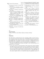
Figure 2-22 shows an example for a DBB test of a machining center of medium
size.
2.3 Calibration of Machine Tools and Robots 61
Fig. 2-21 Structure of DBB instrument.
Source: Kakino
2.4
Collision Detection
Collisions can occur between parts of the machine tool or of the robot, between
workpieces and workpiece clamping devices, and tools. Collisions generate major
disturbances in production and can damage tools, workpieces and parts of the ma-
chine. The adjustment of relevant machine parts such as spindles, spindle hous-
ings, tables, and slides can be destroyed. The time needed for repair can be
hours, days, or even weeks. It is therefore of great importance to avoid collisions
and to detect critical situations which can lead to such accidents. Measures can be
derived from the causes which may lead to collisions [3]. Three phases are distin-
guished:
· the programming phase;
· the set-up and try-out phase; and
· the operation phase.
In each phase there are different causes, as shown in Table 2-1.
According to an investigation which was made in the early 1980s [4], human
causes are the main reason for collisions, constituting 72% of all collisions (Fig-
ure 2-23).
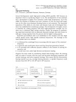
The programming phase constitutes with 13% on average but depends on the
complexity of the parts to be machined, as can be seen from Figure 2-24 [5]. An
investigation of 1848 new NC programm showed a significant correlation with the
number of numerical control (NC) axes.
The measures to avoid such failures are based on geometric or kinematic test
procedures or on simulation techniques. Geometric and kinematic tests which
run in the background of the central cycle or are actuated at suitable incidents or
times can be applied in the set-up and operation phase. The computation time for
the necessary geometric calculation is a limiting factor. Even if the movements of
the machine components are simulated in advance and are checked on collisions,
collision monitoring by software cannot be established exclusively in the back-
2 Sensors for Machine Tools and Robots62
Fig. 2-22 DBB test, deviation from a circular path
2.4 Collision Detection 63
Tab. 2-1 Causes of collisions and measures to avoid them
Phase Functions leading to failure Measure to avoid collisions
Programming Of tool path
Of reference planes
Of tools
Of clamping device
Geometric test procedure
Set-up
try-out
At manual test
By clamping system
By raw material
At choice of tool
Definition of collision space
Collision sensors
Operation By control system
By measuring systems
By tool changing
By wrong part
Definition of collision space
Collision sensors
Fig. 2-23 Causes of collisions in the
working space of NC machine
tools. Source: Streifinger [4]
Fig. 2-24 Error rate of NC programs.
After Flavell [5]
ground of the NC control without affecting the process. Especially for high speeds
and short sets of the parts program the machine may have to wait for the release
of the next program set. Therefore, sensorial approaches have been sought.
Sensors to avoid collisions have so far been based mainly on force monitoring
[5]. These devices have the disadvantage that they cannot really prevent the con-
tact between tool, workpiece, clamping device, and machine or robot components,
but can only avoid major damage. Such sensors send alarm signals to the control
or interrupt autonomously the force flow in the feed drives. An example is given
in Figure 2-25. The force sensor gives a continuous signal to a control unit which
requires a fast processor. The force signal is reached during the set-up phase. A
signal corridor takes care of minor alterations of the measured force and this cor-
ridor is adjusted to a systematic force development with respect to tool wear. If
the corridor is exceeded by an actual signal an interrupt is given to the feed drive
of the machine. Such signals can occur either by tool breakage or by collision.
Both incidents need a fast reaction of the feed drive. In addition to these func-
tions the unit can serve as a wear monitoring system by setting fixed upper limits
for the force. The described system is operating in practice. It is applicable only
for medium-or long-running batches.
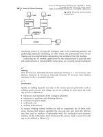
A force sensor for a machining center is shown in Figure 2-26. It is applied to
interrupt the flow of forces which are in this case mainly generated by mass iner-
tia. The device is placed in the feed drive system of a machining center with a
moving column. The kinetic energy stored in the drive chain is
E
kin
1
2
mv
2
f
1
2
n
i1
H
i
Á x
2
1
2-12
where m is the mass of the translatorially moved components such as the column
including the head stock and spindle and v
f
is the feed speed. H
i
are the mo-
2 Sensors for Machine Tools and Robots64
Fig. 2-25 Principle of monitoring
a boring process
ments of inertia of the different components i in the system rotating with angular
speed x
1
. If the rotating components such as motor, gear drive, and ball screw
are decoupled, the collision energy is decreased by one to two orders of magni-
tude because of the fast-rotating parts and the square order influence of the
speed. The figure shows a ball screw drive whose two nuts are fixed by axially act-
ing hydraulic cylinders. If the acting feed force for instance by collision exceeds
the hydraulic force, the respective piston with the nuts moves axially and actuates
a limit switch which gives a signal to the control and stops the feed movement.
The generated collision force depends, of course, on the hydraulic force, on the
time delay from actuating the limit switch to the reaction of the feed drive, and
on the compliance in the force chain.
Optical or acoustic sensors use cameras or acoustic sender and receiver sys-
tems. These principles have not been introduced into practice yet because they
are sensitive to chips, coolant, and particles and therefore have a high disturbance
potential.
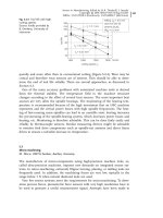
2.5
Machine Tool Monitoring and Diagnosis
The growing investment machine tools and production systems requires their
maximum availability. The complexity of such systems, which are highly auto-
mated and consist of many modules which are linked and have to work together
without failure, increases the risk of breakdowns. Systems containing n modules
which are coupled without redundancy and which have an availability of P
j
<1
each have a total availability of only
P
n
1
P
j
2-13
This means the availability of the total system is always lower than that of the
weakest module. The failure behavior of machine tools was investigated over a
2.5 Machine Tool Monitoring and Diagnosis 65
Fig. 2-26 Feed force collision
sensor. Source: Bohle
large number of machine tools (540 lathes, 401 manufacturing systems and 151
milling machines) (Figure 2-27) [6]. It was seen that the electric and electronic sys-
tems and the auxiliary modules are of dominant interest as far as reliability is
concerned. The repair strategies which were reported from the machine users are
mainly failure or state related.
Monitoring and diagnostic devices are an interesting approach to increase the
availability of a machine tool by decreasing the mean time to repair (MTTR).
Monitoring is the automatic supervision of machine tool functions (or of pro-
cesses, which is reviewed in Chapter 4). The monitoring system has to ensure
that a machine works correctly without malfunctions. The result of its operation
is a corresponding message about the machine state. This test can be performed
according to a plan, periodically or continuously. A diagnosis system goes further,
identifying the incorrect function and the reason for this malfunction. It gives an
indication of the reasons and it is initiated when an incident occurs or upon de-
mand.
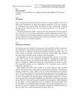
Different methods can be applied for M & D (monitoring and diagnosis) [2]:
· signal-based M & D (heuristic);
· model-based M & D with signal prediction;
· model-based M & D on parameters;
· feature recognition or classification;
· knowledge-based M & D.
Heuristic signal-based systems use experienced states and the respective signals of
machine components, eg, a temperature signal, and compare them with a thresh-
old value of the signal which is set by former experience.
Model-based M & D systems need a description of the system to be monitored.
This description or model is a parametric algorithm or another input-output corre-
2 Sensors for Machine Tools and Robots66
Fig. 2-27 Distribution of machine tool failures. Source: Seufzer [6]
lation of the system which is experimentally determined. The model is able to pre-
dict the relevant behavior of the machine. Figure 2-28 shows as an example the
model structure of a DC drive of a machine tool table. The model is given by the
system describing differential equations or the state variables [7]. Not a single sig-
nal is considered in feature recognition or classification systems but the constella-
tion or cluster of different measured values or multi-dimensional information
such as images is analyzed.
Knowledge-based methods store information about the system behavior and error-
symptom relations. They are used to identify the causes of disturbances, failures,
or interruptions.
The knowledge representation is made by different methods; Figure 2-29 shows
examples. An often applied method is the failure tree representation. The failure
tree is a graphical description of logic links between the failure entrances leading
to a defect (Figure 2-30). The figure shows the malfunction of a valve. Cause
2.5 Machine Tool Monitoring and Diagnosis 67
Fig. 2-28 Model structure of an NC axis. Source: Potthast et al. [7]
Fig. 2-29 Methods of knowledge representation. Source: Seidel [8]
chains for all sources or consequences of the failure are stored in failure trees.
The knots in the tree may be assigned a probability for different errors. The tree
entrances, ie, the elements in the bottom level, are classifications of observable
process or machine states or extracted features.
The advantage of a knowledge representation by a failure tree is that it can be
easily applied in practice. Further, there is no need for an engineer with special
knowledge to generate a failure tree normally. The failure tree can be easily trans-
formed into algorithms for computers. The main disadvantages are the statistical
representation of the knowledge and the limited appropriation for dynamically
transmitting failures. The time dependence cannot or only with difficulty be intro-
duced in failure trees. Also, only known failure descriptions can be considered in
those trees. This might lead to problems for complex systems.
The formulation of heuristic knowledge in rules, ie, ‘if–then’, representations is
also widespread. It is often preferred because the experience and knowledge of
service technicians and machine operators can be easily modeled. It is similar to
the failure tree representation applied to post-failure analysis, which means assist-
ing the operating or service personnel to find out the cause of failure in case of
malfunction. Compared with failure trees, the rule-based representation is more
flexible but it is not simple for more complex applications. Another disadvantage
of the rule-based representation is that the run time depends on the number of
rules and hence it might not be applicable to on-line diagnosis of larger systems.
The speed of rule-based knowledge systems can be accelerated by dividing the
knowledge basis and by import and export of rules, by efficient inference algo-
rithms, and by using compilers for the knowledge basis.
M & D systems should be well integrated into the control system of a machine
tool. Nevertheless, the machine should be able to operate even if the M & D sys-
tem fails. This means that the M & D functions have to work independently and
parallel to the machine functions but they have to be synchronized with them. Set
data of the control and additionally status and sensor signals of the machine are
used for the synchronization. The following criteria should be taken into consid-
eration under the prerequisites of flexibility, modularity, and extensibility:
2 Sensors for Machine Tools and Robots68
Fig. 2-30 Example of failure tree representation. Source: DIN 25424
· the data processing functions should be implemented in small independent
and reusable modules;
· data and data processing functions should be clearly separated;
· the mechanism to control the data processing functions should be interchange-
able to be able to apply different methods with variable flexibility;
· the architecture must be multiprocessor treatable and multicomputer applica-
ble.
Figure 2-31 shows the internal structure of a system which follows these require-
ments. The complete system is built up as a network of separate, equally struc-
tured run-time modules which act autonomously.
The internal elements of a run-time system and the interfaces between them
are shown in Figure 2-32. In addition to the communication interface the run con-
trol is the central kernel which determines the data processing functions accord-
2.5 Machine Tool Monitoring and Diagnosis 69
Fig. 2-31 Internal structure of the M & D kernel system. Source: Seidel [8]
Fig. 2-32 Information exchange between elements of the run-time system. Source: Seidel [8]
ing to stored data of the knowledge base and the actual state of the machine. The
data processing functions are implemented in separate program modules in
which algorithms for signal processing tasks, communication functions, and func-
tions to switch on sensors and actuators are integrated.
Demands on the availability of machine tools grow with the investment. Their
complexity needs specific know-how to maintain or repair them. The consequence
is that teleservice and telediagnostics are of growing interest. The economic bene-
fits result from the fact that M & D systems may be expensive. It is interesting to
use them only if they are necessary by telecommunication and not to place them
locally. Several machine tool manufacturers already offer tele-M & D systems. Via
an RS-232 interface the service personnel can communicate with the machine
over long distances. The test can be run by a local machine operator in collabora-
tion with the service technician at the manufacturer’s office. It is also possible to
run a part program to repeat critical states of the machine. Some machine control
units are provided with ISDN interfaces. The service center can load specific diag-
nosis programs and evaluate the test results.
2 Sensors for Machine Tools and Robots70
2.6
References
1 Tönshoff, H. K., Werkzeugmaschinen-
Grundlagen; Berlin: Springer, 1995.
2 Tönshoff, H. K., Wulfsberg, J. P., Kals,
H. J.J., Koenig, W., van Luttervelt,
C. A., Ann. CIRP 37 (1988) 611–622.
3 Weck, M., Werkzeugmaschinen, Vol. 2; Ber-
lin: Springer, 1997.
4 Streifinger, E., Dr Ing. Dissertation; TU
München, 1983.
5 Flavell, N. L., in: Proceedings of 20th Annual
Meeting and Technical Conference; Cincin-
nati, OH: Numerical Control Society, 1983.
6 Seufzer, A., Dr Ing. Dissertation; Univer-
sität Hannover, 1999.
7 Potthast, A., Zughaibi, N., Suwalski, I.,
et al., ZwF 87 (1992) 269–273.
8 Seidel, D., Dr Ing. Dissertation; Universi-
tät Hannover, 1993.