Cảm biến trong sản xuất P13
Bạn đang xem bản rút gọn của tài liệu. Xem và tải ngay bản đầy đủ của tài liệu tại đây (165.97 KB, 10 trang )
The main problem is that the cause and effect of certain faults are still unclear.
More research is required to find out which sensors are more adequate for moni-
toring specific faults so that redundant information can be minimized. Further-
more, more work has to be done to reduce the size and cost of the sensors so that
a ‘complete sensing’ approach can be seriously taken into account.
277
4.5.5
References
1
Barthel, K., Trunzer, W., Laser-Praxis
(1994) 10.
2
Anon., Opto Laser Eur. (1997) 3.
3
Schwede, H., Kramer, R., in: Proceedings
of ICALEO 1998, Orlando, FL;
www.primes.de.
4
Eg, Prometec UFC60; www.prometec.com.
5
Www.precitec.com.
6
Friedel, R:, EuroLaser (2000) 1.
7
Tönshoff, H. K., Schumacher, J., in:
Proceedings of ICALEO 1996, Detroit, MI.
8
Ikeda, T., Kojima, T., Tu, J. F., Ohmura,
E., Miyamoto, I., Nagashima, T., Tsubo-
ta, S., Ishide, T., in: Proceedings of ICA-
LEO 1999, San Diego, CA.
9
Www.precitec.som/PPS130E.htm.
10
Rinke, M., Dissertation; Düsseldorf: VDI-
Verlag, 2000.
11
Graumann, C., Dissertation; Düsseldorf:
VDI-Verlag, 1998.
12
Tönshoff, H.K., Alvensleben. v. F., Os-
tendorf, A., Hillers, O., Stallmach,
M., in: Proceedings of Photonics East, 1999,
Boston, MA.
13
Seto, N., Katayama, AS., Matsunawa,
A., in: Proceedings of ICALEO 1999, San
Diego, CA.
4.6
Electrical Discharge Machining
T. Masuzawa, University of Tokyo, Tokyo, Japan
4.6.1
Introduction
Electrical discharge machining (EDM) has been known as one of the non-tradi-
tional machining processes since its invention in early the 1940s. However, cur-
rently, EDM is one of the most commonly used processes in various kinds of fac-
tories. Most EDM machines are used in the field of die and mold making.
The material removal mechanism in the case of EDM is completely different
from that in the case of highly conventional machining processes such as cutting
and grinding. It is based on melting and vaporization of workpiece materials by
heating introduced by a spark or, more precisely, by a transient arc discharge.
Thus the machining force is a minor or, rather, a negligible parameter in the
control of this process. On the other hand, precise, dynamic control of the spark
gap is essential for stable repetition of the discharge. These features make the
control system unique and, consequently, the sensing strategy must be different
from that in the case of conventional machining processes.
Sensors in Manufacturing. Edited by H.K. Tönshoff, I. Inasaki
Copyright © 2001 Wiley-VCH Verlag GmbH
ISBNs: 3-527-29558-5 (Hardcover); 3-527-60002-7 (Electronic)
4.6.2
Principle of EDM
From the viewpoint of shape specification of the workpiece, EDM is included in
the same group as cutting where the shape of the tool is copied on to the work-
piece or further modified according to the trajectory of the tool movement (rela-
tive to the workpiece). The tool is referred to as the electrode.
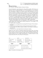
The main difference between EDM and conventional machining processes such
as cutting is in the mechanism of material removal. The material removal process
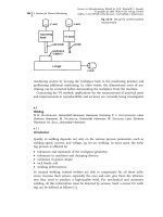
in EDM is illustrated in Figure 4.6-1.
A voltage pulse from a pulse generator initiates and maintains a short arc dis-
charge through the dielectric fluid in the gap between the electrode and the work-
piece. The discharge heats the surface layer of the workpiece locally and melts
(and also partially vaporizes) a small part of the workpiece. The simultaneous va-
porization of the fluid produces a high pressure and the molten material disinte-
grates into microsize particles, forming a shallow crater on the workpiece surface.
The process leading to this crater formation is repeated over the entire work-
piece surface facing the electrode, producing a thin cavity layer on the workpiece.
By continuing this process with the feed of the electrode facing downward, the en-
tire electrode shape is replicated on to the workpiece.
4 Sensors for Process Monitoring278
Fig. 4.6-1
Principle of EDM
The discharge also forms a crater on the electrode. However, specifically chosen
discharge conditions can minimize the size of the crater to, for example, less than
0.1% of the crater size on the workpiece.
4.6.3
Process Control
Discharge occurs only when the gap distance is within a certain range. If the dis-
tance is too large, the discharge cannot be initiated. If the distance is too small, a
short-circuit occurs after the discharge, because a bridge is formed by the molten
material. This short-circuit terminates any further discharge.
Because of the above characteristics, gap control is the main issue in the case of
EDM control
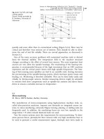
A constant electrode feed rate is not usually adopted, because the occurrence of
the discharge is a more or less random process and the speed of removal in the
electrode feed direction is not constant.
Therefore, the control strategy involves maintaining a constant gap distance
throughout the operation. However, direct in-process measurement of the gap dis-
tance is almost impossible. The main reasons for this are that (a) the gap is very
narrow, 0.5–50 lm., and (b) the gap distance varies throughout the machining
area and the nearest point determines the occurrence of the discharge and short-
circuit. For these reasons, indirect detection of the gap distance is adopted in all
EDM machines.
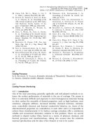
The basic control algorithm is shown in Figure 4.6-2.
4.6.4
Sensing Technology
In EDM, sensing technology is mainly required for obtaining information on the
gap condition. As described previously, the information finally required is on the
gap distance, which cannot be obtained directly. In order to overcome this diffi-
culty, relationships between the gap distance and other detectable parameters have
been analyzed. The parameters that represent the state of the gap condition are
used as control parameters.
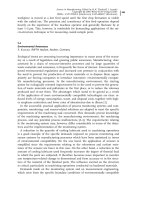
Fortunately, as the removal mechanism of EDM is based on an electrical phe-
nomenon, useful information is obtainable from the electrical parameters of the
circuit for discharge. The most frequently used parameters are the gap voltage
and the current through the gap, as shown in Figure 4.6-3.
Some other parameters can also provide information on the machining status.
The more promising ones are the electromagnetic radiation from the arc and the
acoustic radiation caused by discharges.
In the detection of these parameter values, sensors may play a useful role. To
date, sensors have played a minor role in EDM control, because the more useful
parameters, such as the voltage and the current, can be detected without special
sensors. However, in some cases, sensors offer merits from the viewpoints of im-
proved technology and economics.
4.6 Electrical Discharge Machining 279
The following is an overview of the major technologies used in obtaining gap
information.
4.6.4.1
Gap Voltage
In EDM, the gap voltage contains numerous information. The status of the gap is
indicated by the gap voltage as shown in Figure 4.6-4.
The figure shows only typical examples but there also occur various transient
and combined types of voltage waveforms. These voltage pulses are input into the
control system and statistical calculation is performed which provides the neces-
sary values that can be compared with the set values for proceeding according to
the flow chart shown in Figure 4.6-3.
In this detection of gap voltage, no special sensor is usually required. A conven-
tional high-impedance probe commonly used for measuring equipment such as
an oscilloscope can be used without any problems. The voltage range is usually
from 50 to 200 V.
4 Sensors for Process Monitoring280
Fig. 4.6-2
Basic control
algorithm for EDM
When very short pulses are applied for micromachining or very fine finishing, a
special pulse circuit called a ‘relaxation-type generator’ is often used. In such a
case, obtaining the input from a probe is difficult because the impedance of the
gap is too high when it is open-circuited. Moreover, the input capacitance of the
probe may change the energy of the discharge. Special voltage sensors may pro-
vide a solution to this problem, but in most cases the detection of the gap voltage
is abandoned and replaced by the detection of the current through the gap. This
method is discussed in the next section.
4.6.4.2
Current Through Gap
Since discharges for EDM are the current flow from the electrode to the work-
piece (or in the reverse direction), the dynamic value of the current through the
gap contains numerous information. The typical relationship between the current
waveform and the status of the gap is shown in Figure 4.6-5. As is apparent when
Figures 4.6-4 and 4.6-5 are compared, the current waveform can be as useful as
the gap voltage described earlier. Since the difference between the cases of normal
discharge and abnormal arc is only the high-frequency component in the wave-
form, control using current information requires more careful data processing
than that using gap voltage.
For detecting the current waveform, two types of devices are currently used.
(A) Shunt resistor. The most conventional and reliable method involves using a
low-resistance resistor inserted in the loop of the gap current flow, as shown in
4.6 Electrical Discharge Machining 281
Fig. 4.6-3
Parameters
used for controlling EDM
Fig. 4.6-4
Voltage change
according to the status of gap