Cảm biến trong sản xuất P12
Bạn đang xem bản rút gọn của tài liệu. Xem và tải ngay bản đầy đủ của tài liệu tại đây (173.53 KB, 6 trang )
4 Sensors for Process Monitoring272
33
Heuer, W., Dissertation; Universität Han-
nover, 1992.
34
Tönshoff, H.K., Falkenberg, Y., Mohl-
feld, A., IDR Ind. Diamanten Rundsch. 1
(1995) 43–48.
35
Heinzel, C., Dissertation; Universität Bre-
men, 1999.
36
Karpuschewski, B., Brunner, G., Falk-
enberg, Y., Jahrbuch Schleifen, Honen,
Läppen und Polieren; Essen: Vulkan-Verlag,
Ausgabe 58, 1997, pp. 146–158.
37
Brinksmeier, E., Heinzel, C., Witt-
mann, M., Ann. CIRP 48 (1999) 581–598.
38
Chang, Y. P., Dornfeld, D. A., Ann.
CIRP 45 (1996) 331–334.
39
Sabotka, I., Dissertation; TU Berlin, 1991.
40
Funck, A., Dissertation; TU Berlin, 1994.
41
Bönsch, G., Dissertation; RWTH Aachen,
1992.
42
Choi, G. S., Choi, G. H., Int. J. Machine
Tools Manuf. 37 (1997) 295–307.
43
Williams, R.E., J. Manuf. Sci. Eng. Trans
ASME 120 (1998) 264–271.
44
Popp, C., Dissertation; Universität Hanno-
ver, 1992.
45
Walter, A., Dissertation; Universität Han-
nover, 1995.
46
Zinngrebe, M., Dissertation; Universität
Hannover, 1990.
47
Fuchs, A., Dissertation; TH Darmstadt,
1992.
48
Ota, M., Ando, S., Oshima, J., presented
at the 2nd International Symposium on
Magnetic Bearings, Tokyo, July 12–14,
1990.
49
Rowe, W. B., Allanson, D., Thomas, A.,
Moruzzi, J. L., presented at the CIRP
Workshop of STC ‘G’. Paris, January 1993.
50
Memis, F., Dissertation; RWTH Aachen,
1996.
51
Tönshoff, H. K., Karpuschewski, B.,
Hinkenhuis, H., Regent, C., in: VDS-
Fachtagung ‘Schleiftechnik im Wettbewerb’,
9–10 October 1997, Aachen, pp. 8/1–13.
52
Tönshoff, H. K., Karpuschewski, B.,
Paul, T., VDI-Z. 133 (7) (1991) 58–63.
53
Paul, T., Dissertation; Universität Hanno-
ver, 1994.
54
Rowe, W. B., Yan, L., Inasaki, I., Malkin,
S., Ann. CIRP 43 (1994) 1–11.
55
Inasaki, I., VDI-Ber. 1179 (1995) 31–45.
4.5
Laser Processing
V. Kral, O. Hillers, Laser Zentrum Hannover, Hannover, Germany
4.5.1
Introduction
The field of laser manufacturing has been expanding rapidly in the last 20 years.
New materials and new laser sources have considerably increased the potential of
laser applications. This expansion has led to a necessity for higher quality and re-
producibility when using lasers. To satisfy this demand, a considerable amount of
research has been expended into the use of sensing for laser applications.
The goals of implementing sensing technology in laser manufacturing can be
categorized into two groups.
1. Sensors that monitor the process parameters. These measure the external variables
that affect the laser process. This may mean monitoring of the beam character-
istics, the workpiece-head distance, the geometrical accuracy of the workpiece,
the process gas, filler material feed, the material quality of the workpiece, and
the laser mode, for example. All these parameters have an undeniable effect on
the process quality and can be monitored using the appropriate sensors. If
Sensors in Manufacturing. Edited by H. K. Tönshoff, I. Inasaki
Copyright © 2001 Wiley-VCH Verlag GmbH
ISBNs: 3-527-29558-5 (Hardcover); 3-527-60002-7 (Electronic)
these parameters are supervised and controlled, then theoretically no decrease
in quality should occur. Currently, such sensors are being used for monitoring
purposes (ie, preventative measures). A trend towards closed-control systems
will only be possible when all the process parameters can be individually con-
trolled.
2. Sensors that monitor the process quality. These sensors are used to monitor the
process by measuring its effects. A common approach is to measure the pro-
cess radiation using optical sensors. Other methods such as the measuring of
process-induced vibrations, thermal effects, or meltpool dynamics are also
being extensively researched. By correlating signal variation with quality faults,
these systems can monitor the quality of the process. The use of such systems
can eliminate the need for destructive off-line quality control methods.
Unfortunately, laser processes are so complex that no full proof system has yet
been discovered that guarantees 100% quality. This problem can only be solved by
mixing parameter control sensors and process control sensors.
4.5.2
Parameter Monitoring Sensors
The goal of implementing these types of sensors is to measure all the relevant
process parameters so that any changes in the quality due to parameter variations
can be predicted. To achieve this, the source of error in the process has to be iden-
tified. Common sources of error are due to changes in workpiece geometry, work-
piece material quality, laser beam characteristics, the focus position, and process
gas pressure.
4.5.2.1
Sensors for Identifying Workpiece Geometry
Imaging systems, such as the SCOUT [1], are used as seam tracking devices. A
camera is mounted on the robot arm and allows the system to adjust the robot
motion relative to the seam position. Camera-based systems often have problems
when dealing with highly reflective surfaces, since scratches and reflections can
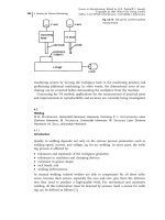
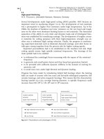
be misinterpreted. Another approach is the use of a mechanical guide to follow
the seam [2], as shown in Figure 4.5-1. The use of this method is limited by the
feed rate, since the mechanical guide is usually spring loaded. The advantage is
that a certain robustness is guaranteed.
4.5.2.2
Sensors for Identifying the Workpiece Quality
Both the material quality and the surface cleanliness can considerably affect laser
welding or cutting processes. Errors due to unacceptable material quality are diffi-
cult to detect on-line. One approach is to use the process radiation from a high-
power laser pulse to classify the type and quality of the steel. The process radia-
tion is analyzed using a spectral analyzer, and the individual material-specific
4.5 Laser Processing 273
emission peaks are correlated with that of a reference steel. Using this method,
undesirable changes in alloy concentration can be detected.
4.5.2.3
Sensors for Beam Characterization
In laser processing, the quality of the beam plays a considerable role in achieving
high process quality. For this purpose, sensors are being developed for monitoring
the beam power distribution. One common approach is to use a shaft with a pin-
hole that scans across the beam [3]. Coupled to a mirror, the radiation is reflected
to a sensor. With such a system, the intensity distribution across the beam is mea-
sured. Another system requires the placing of a thin wire grid in the beam path
[4]. From the temperature change of the individual wires, a complete beam power
distribution can be reconstructed.
4.5.2.4
Focal Position and Gas Pressure
A drift between the workpiece and the focusing head is often the cause of process
faults. Particularly in cutting applications, keeping the focus within the material is
important. To solve this problem, capacitive sensors measure the distance to the
workpiece and using a control loop, a compensating motion is applied when sur-
face irregularities appear [5]. In addition, more modern systems control the pro-
cess gas pressure so that no fluctuations can affect the final cut [6]. These sensors
are common for two-dimensional applications but have not yet been used in
three-dimensional applications.
4 Sensors for Process Monitoring274
Fig. 4.5-1
Tactile seam tracking system
(Laser Zentrum Hannover)
4.5.3
Quality Monitoring Sensors
Research has been most active in the field of process monitoring. All measurable
effects of the laser process are being studied. The sensors used concentrate on op-
tical, acoustic, and visual-based sensing.
4.5.3.1
Optical Sensors
These sensors are used in the most common systems found on the market today.
The principle is based on analyzing the process radiation [7]. Depending on the
manufacturer, the process radiation is acquired either in- or off-axially from the
process point.
Some research has shown that a combination of off- and in-axis radiation can
be used for higher reliability [8]. The wavelengths that are being monitored can
vary from source to source, but most sensors used are photodiode-based systems
monitoring radiation within the visual and near-infrared regions of the spectrum
(ie, 400–1000 nm). Other sensors measure the reflected laser radiation. A more
costly, but more thorough approach is to use on-line spectral analysis, since indi-
vidual wavelengths can be taken into account. Such a solution increases the com-
plexity of the failure identification algorithms, and has so far not been industrially
implemented.
The optical sensor approach is the most promising approach to identifying
faulty laser processes. Unfortunately, even though variations in the process radia-
tion can be correlated with faults, some faults are not always detectable by observ-
ing the process radiation signals.
4.5.3.2
Acoustic Sensors
Another approach is to use microphones or ultrasonic sensors to measure process
faults. This is particularly useful in the piercing phase of a cutting process [9].
Using these sensors, the piercing time can be optimized. Other approaches in la-
ser welding have shown that it is possible to correlate the acoustic signals with
weld-pool vibrations when a pulsed laser process is being used. In micro-structur-
ing using excimer lasers, ultrasonic measurements on the workpiece have shown
that the removal rate for each pulse can be monitored [10].
4.5.3.3
Visual-based Sensing
This approach deals with the complete visualization of the effects of the process.
In welding, for example, key-hole diameter and weld-pool dynamics [11] can be
monitored using charge-coupled device (CCD) cameras. The only difficulty lies in
choosing the proper filter so that the bright process radiation does not overexpose
the image. This is particularly important when dealing with processes that pro-
4.5 Laser Processing 275
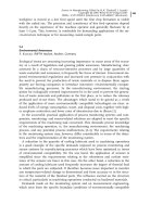
duce considerable plasma radiation. Another approach is to use thermal imaging
after the process. From the thermal distribution, irregularities in welding pro-
cesses can be identified (Figure 4.5-2). To increase the signal processing speed, in-
frared line-arrays can be implemented [12]. Another purely scientific approach is
to use X-ray imaging to identify the vertical melt-pool dynamics [13]. Such a re-
search tool has been used to identify the formation of pores in welds.
Unfortunately, visual systems are complex and expensive. Fast feature extraction
software is necessary. For this reason they are rarely used in industrial applications.
4.5.4
Conclusion
As can be seen, the sensors that can be used in laser processing applications are
varied. Ultimately, what needs to be known is the goal of the sensing system. A
well-identified quality problem could be monitored by some of the sensors de-
scribed above if the fault symptoms are known (eg, fluctuation of the process ra-
diation due to gap variations in overlap welding). To identify all the symptoms,
one would ultimately require a ‘complete sensing’ of the process. This is complex
and expensive; currently such a solution cannot be realistically envisioned for use
in industrial applications.
4 Sensors for Process Monitoring276
Fig. 4.5-2
Thermal distribution on seam
surface with two related cross sections
and an experimental set-up for ‘behind-
process’ thermal inspection