Cảm biến trong sản xuất P14
Bạn đang xem bản rút gọn của tài liệu. Xem và tải ngay bản đầy đủ của tài liệu tại đây (438.76 KB, 22 trang )
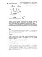
machining system by moving the workpiece back to the machining position and
performing additional machining. In other words, the dimensional error of ma-
chining can be corrected before demounting the workpiece from the machine.
Concerning the VS method, applications for the measurement of practical parts
and improvements in reproducibility and accuracy are currently being investigated.
4.7
Welding
H. D. Haferkamp, Universität Hannover, Hannover, Germany, F. v. Alvensleben, Laser
Zentrum Hannover, M. Niemeyer, Universität Hannover, W. Specker, Laser Zentrum
Hannover, M. Zelt, Universität Hannover
4.7.1
Introduction
Quality in welding depends not only on the various process parameters such as
welding speed, current, and voltage, eg, for arc welding. In most cases, the weld-
ing process is affected by:
· tolerances and mismatch of the workpiece geometry;
· tolerances in machines and clamping devices;
· variations in groove shape;
· tack beads; and
· welding deformations.
In manual welding, trained welders are able to compensate for all these influ-
ences, because their senses, especially the eyes and ears, give them the informa-
tion they need to produce a high-quality weld. For mechanical and automatic
welding, all this information must be detected by sensors. Such a sensor for weld-
ing can be defined as follows [1]:
4 Sensors for Process Monitoring286
Fig. 4.6-10
Set-up for on-the-machine
measurement
Sensors in Manufacturing. Edited by H.K. Tönshoff, I. Inasaki
Copyright © 2001 Wiley-VCH Verlag GmbH
ISBNs: 3-527-29558-5 (Hardcover); 3-527-60002-7 (Electronic)
‘A detector, if it is capable of monitoring and controlling welding operation
based on its own capacity to detect external and internal situations affecting
welding results and transmit a detected value as a detection signal, is called as
a sensor. Moreover its whole control device is defined as a sensor system
(control system)’.
In this definition, the external situation refers to all workpiece-related geometric
values such as changes in dimensions of the welding groove, position of the weld-
ing line, and presence of component obstacles or tack welds. The internal situa-
tion covers factors such as the shape of the welding arc and molten pool, the
penetration depth, and all kinds of effects related to the welding process itself [2].
In general, every physical principle which is able to deliver information about
an object’s shape and position may be the basis of a sensor. For welding sensors,
the special ambient conditions and the industrial constraint for economic effici-
ency, however, cause many additional restrictions, such as:
· process-induced disturbances, such as light, heat, fume, spatter, and electromag-
netic fields, must not influence the sensor;
· the sensor must be satisfactorily durable for welding ambience;
· it must be compact in size and light weight, so that there are no restrictions in
handling and accessibility;
· the sensor system must only generate low costs;
· it should have easy maintenance.
Owing to this and because of the very complex process, so far no universal sensor
for welding is available which meets all these requirements and is able to detect
all the various kinds of information by which the welding process is influenced.
For the user, it is necessary to select the most satisfactory sensor type for every
special welding task [2–5].
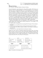
In general, a classification of welding sensors can be made by their functional
principle. In Figure 4.7-1 such a classification of sensors for welding is shown in
accordance with [3]. Further classification is made by the physical principle on
which the sensor is based.
4.7.2
Geometry-oriented Sensors
Geometry-oriented sensors gather their information from the geometry of the
welding groove itself or from an edge or a surface which has a defined relation to
the seam. Geometry-oriented sensors can be divided into contact and non-contact
types.
4.7.2.1
Contact Geometry-oriented Sensors
Contact sensors permit the detection of the welding start/end point and seam
tracking with comparatively low technical expenditure. The first seam tracking
4.7 Welding 287
systems in welding were based on the mechanical tracing of a gap or an edge by
a probe and the direct transformation of movements to the torch by way of ful-
crums. The form of the probe, eg, as a ball, roll, or ring, must be adjusted to the
groove geometry. Further technical development leads to electromechanical sensor
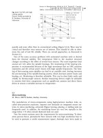
systems, which convert the probe movement into electrical signals. Generally,
there are two different kinds of these sensors. One group operates with limited
switches, which deliver an on/off output signal, to track the seam stepwise. The
other group uses potentiometers or differential transformers to generate a dis-
tance-proportional output signal, which allows continuous seam tracking. In Fig-
ure 4.7-2, the principle of these two sensor groups is shown [1, 6, 7].
The probe may have one or two degrees of freedom, so it is able to compensate
for most two-dimensional deviations of the weld seam. Usually, the contact probe
sensor is in a fixed position ahead of the welding torch, which causes some lim-
itations in the shape of the welding seam. Because of the distance between sensor
4 Sensors for Process Monitoring288
Fig. 4.7-1
Classification of sensors
Fig. 4.7-2
Contact probe sensors: (a) limited switch type; (b) potentiometer type
and welding torch, which leads to deviations on curved seams, this method is
commonly used for welding straight-lined seams.
In order to apply contact sensors to welding curved seams, several techniques
have been developed. Bollinger [8] described a method that is based on the turn-
ing of the complete fixed torch-sensor unit around defined axes. From the mea-
sured turn angles, the path feed rate of the different axes is calculated. Neverthe-
less, this system leads to some deviation on seams with a small radius of curva-
ture. To avoid this, it is necessary to monitor the welding seam using the sensor,
prior to welding, and store the deviation values of the seam. With the stored coor-
dinates, the system allows the welding of small curve radii with constant torch ori-
entation. However, the system is not suitable for welding closed contours. The
maximum deviation angle to the mean welding direction is given by the author as
±608.
Another method for contact sensors for welding curved seams is based on the
mechanical decoupling of the sensor and torch motion [9]. In these systems,
called memory delay playback, the sensor is mounted on a separate x-y drive
block, which allows tracing of the shape of the groove independent of the torch
movement. The groove deviation values are stored, and based on the welding
speed and the distance between sensor and torch, the correct position of the weld-
ing torch is adjusted when it is moving towards the former sensor position. This
sensor system leads to satisfactory results, even in welding small bending radii.
Nevertheless, this system also is not capable of welding closed contours. It is just
able to compensate deviation angles of ±308 to the mean welding direction.
Another way of using a contact sensor for welding any curved seam is detection
of the seam deviation prior to welding, and compensation of the programmed
seam line by the measured deviation values, as described by Schmidt [10]. Prior to
the first weld, a contact probe sensor is mounted in lieu of the torch gas cup, and
the welding robot senses the deviation of the workpiece weld line to the pro-
grammed one. After this sensing cycle, the normal gas cup is mounted, and the
robot starts to weld the rectified seam line. This method calls for a separate mea-
sure cycle prior to every weld, and is not able to compensate for deviations that
occur during welding, eg, due to thermal distortion.
A seam tracking system has been described [11, 12] which was developed for
laser beam welding of three-dimensional fillet welds using an industrial robot.
The mechanical sensor consists of a metal tracer pin, which is dragged along the
fillet joint at a fixed distance ahead of the laser spot. Positional changes induce
potentiometric variations at the head of the pin. The sensor feeds these variations
to an electronic controller as a stream of analog data. The controller then guides
the laser spot accordingly, by means of two servo motors which give the vertical
and transverse motion of the laser head, using commercial systems, within a
range of ± 7.5 mm and with an accuracy of ± 0.1 mm. Welding speeds up to 6 m/
min are possible with current systems.
Generally, the use of contact probe sensors is limited by the wear of the probe
itself. Because of permanent contact to the workpiece, there is marked friction
wear, which decreases the probe lifetime. Further limits are caused by the accessi-
4.7 Welding 289
bility of the joint. The additional sensor mounted in front of the torch means a
significant enlargement of the tool, and so welding in confined areas is restricted.
Nevertheless, contact probe sensors have been widely used in many industrial
applications for a long time, especially owing to their simple design and easy han-
dling and maintenance.
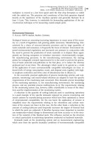
Another special contact sensor is the electrode or wire contact sensor. This is a
sensing method which was developed for arc welding robots. It is able to detect
deviations between a taught point of the robot path and the present position of
the welding torch. In Figure 4.7-3, the principle of this sensing method is shown.
The basic idea of this sensor is to use the torch as a switch in an electric cir-
cuit. In this circuit, the workpiece surface and the welding wire have different po-
larity. When the wire comes into contact with the workpiece, a change in electric
current or voltage can be detected. The difference of the taught point and the ac-
tual position can be calculated, and the real position of the workpiece is defined.
For using the welding wire as a probe, the stick-out length of the wire must be de-
fined. Therefore, wire extension may be determined by automatically cutting it to
length prior to sensing, or it can be calculated by sensing a machine reference
point, which has no initial deviations prior to workpiece sensing. Another method
is the use of the welding torch gas cup as the contact dip [13–16].
The electrode contact sensor is industrially used in robotic welding to detect var-
iations of the starting and end points of welds and of the length of welds and in
sensing the form of the welding gap prior to welding. They are simply designed,
easy to use, and not subject to wear. This sensor type is able to achieve an accu-
racy of ± 0.2–0.3 mm in position detection. Beyond that, they cause no restrictions
in accessibility of the joint, because there are no additional extensions to the torch
[14–17].
In general, the use of these kinds of sensor can be limited by all kinds of insu-
lating coatings on the workpiece, such as primer or oxide layers. Furthermore, the
electrode contact sensor is not able to allow for deviations which occur during
welding, eg, due to thermal distortion. Hence, it is usually used for short welds or
in combination with an additional seam tracking sensor, eg, a through-the-arc sen-
sor [13–17].
4 Sensors for Process Monitoring290
Fig. 4.7-3
Principle of an electrode
contact sensor
4.7.2.2
Non-contact Geometry-oriented Sensors
A further development in sensor systems is the non-contact geometry-oriented
sensors. These sensors are based on various physical principles of measurement
(see Figure 4.7-1). Generally, they deliver information about the workpiece shape
and its position in space. Depending on the sensitivity and accuracy of the sens-
ing system, non-contact geometry-oriented sensors are able to detect the start and
end points of welds and track weld seams. The most commonly used types in this
category of sensors are based on optical, electromagnetic, and acoustic measure-
ment. The fourth category of pneumatic sensors from the list in Figure 4.7-1 use
the impact pressure of a gas nozzle to detect the distance between the workpiece
surface and the sensor. This sensing method is not commonly used in welding
processes at present.
In laser welding long seams, the problems resulting from the geometric accu-
racy of the workpiece become a decisive factor. Industrial robots are often used to
guide the laser head or the welding torch along the workpiece. In laser welding
the robot-guided beam must follow the (three-dimensional) seam geometry accu-
rately, because focus diameters are typically in the range 0.15–0.5 mm. Addition-
ally, any movement out of the focal plane (eg, the distance workpiece lens
changes) can cause a defective weld. The robot is usually programmed manually,
using a time-consuming point-by-point basis, so that curves are often estimated.
In addition to that in arc welding, the process caused thermal distortion of the
workpiece, often leading to geometric deviations of the joint line.
Optical sensors, which use the topography of the workpiece surface in order to
detect the weld seam, belong to the non-contact geometry-oriented type. The basic
principle of the optical measurement used in this sensor group is a light-section
procedure. Using a laser diode, a line-shaped laser beam is projected on to the
4.7 Welding 291
Fig. 4.7-4
Principle of a laser-stripe sensor
workpiece (see Figure 4.7-4). A variation in the distance between sensor and work-
piece leads to a change of the reflected beam position. This reflected beam is mea-
sured by a charge-coupled device (CCD) camera whose data are processed by a
PC, in order to calculate the workpiece surface contour. These data can be used
for seam tracking, groove shape detection, and detecting weld start/end points
[18–23].
The data of the sensing system are transmitted to the handling system, in order
to correct the beam or torch position on the workpiece. Usually, it controls, eg,
the robot directly via CNC commands. The measurement accuracy of commercial
systems is 0.025 mm, and these systems are suitable up to maximum welding
speeds of 15 m/min. The positioning accuracy also depends on the handling sys-
tem. Both optical components, laser diode and CCD camera, are adapted to the la-
ser head and to the welding torch, which makes it sensitive to alignment, dust,
fumes, and spatter. The optical method has the drawback that reflections and
scratches on the workpiece surface may cause the system to go astray.
Electromagnetic sensors are non-contact geometry-oriented sensors, which gain
their information by the effect of metallic materials on electromagnetic fields.
These sensors, used to detect position or displacement, are classified into capaci-
tance and eddy current types. Capacitance sensors measure the capacity between
the workpiece and a small electrically conductive plate. They offer the possibility
of distance sensing. Matthes et al. [24] described a capacitance sensor for seam
tracking in V-grooves. The sensor signal of capacitance sensors is heavily vitiated
by deviations in flatness or parallelism of the workpiece surface. Hence this kind
of sensor ordinarily is not used in welding, but sometimes is in thermal cutting
[2, 3].
The eddy current type is based on the interaction of metallic materials and alter-
nating magnetic fields. The sensor induces eddy currents in the near-surface
range of the workpiece. These eddy currents influence the inductance of the sen-
sor coil, depending on the distance between sensor and surface. From this influ-
ence, a distance-dependent electrical signal is obtained [2, 3, 25–28]. The principle
is shown in Figure 4.7-5.
Depending on the frequency of the eddy current, the sensor reacts in different
ways to the various magnetic characteristics of the workpiece materials. Sensors
4 Sensors for Process Monitoring292
Fig. 4.7-5
Electromagnetic sensor, eddy
current type
with low-frequency eddy currents are only suitable for ferromagnetic materials,
whereas high-frequency sensors are applicable to both ferromagnetic and non-
magnetic materials [27, 29].
Electromagnetic sensors with one coil system are limited to detecting the dis-
tance to the workpiece in one direction. Hence they are only able to adjust the
torch’s height or lateral deviation. Sensors with a combination of several coil sys-
tems, however, allow sensing a welding groove in every direction. In addition to
height and lateral deviation, these systems can detect changes in the direction of
the welding groove, the beginning and the end of a groove and some changes in
the setting angle of the welding torch [29–32].
Because of the geometric distance between the torch and the electromagnetic
sensor, these systems are affected by some deviations on curved welds (compared
with contact probe sensors). To avoid these deviations, several methods have been
developed. In one system [29], the sensor rotates around the torch, and the sensor
signal is connected to the direction by a turn angle transmitter. Considering the
welding speed and direction, the deviation between the sensor and torch can be
compensated by the control system. This allows one to track curved seams in
every direction with satisfactory precision.
For tracking fillet welds, another possibility is to sense the weld flanks by a col-
lateral arrangement of two sensors to the torch [2, 33]. Every sensor is arranged
perpendicular to one flank. In that way, by sensing and adjusting the distance to
them, the torch follows the seam. An eddy current sensor has been described [34]
which is concentric to the torch and integrated in the gas cup. This leads to a
very compact design, so accessibility problems are minimized.
In general, eddy current sensors are able to compensate deviations with an ac-
curacy of ± 0.15–0.5 mm. They are suitable for detecting almost every kind of
groove shape. In butt joint welding they are able to track gaps up to a width of
0.05 mm. Nevertheless, the use of these sensors is limited in several ways. In gen-
eral, some additional extension of the torch is necessary, so the accessibility of
seams is limited. When welding butt joints, filler and cover passes are difficult to
track using eddy current sensors. Edge misalignment on butt joints causes devia-
tions to the center of the weld, so very exact preparation of the workpiece and reli-
able fixture is essential for accurate seam tracking. Moreover, eddy current sen-
sors are affected by any foreign magnetic field in the sensing area. Even geo-
metric changes in the region of the seam, such as clamping fixtures, tack welds,
workpiece thickness, and material non-homogeneities, can influence the sensor
signal [3, 26, 29, 34–36].
In spite of these disadvantages, eddy current sensors are widely used in many
industrial applications. Because of their robust design, universal application cap-
ability, and comparatively low cost, their application is economical for a great vari-
ety of sensor tasks.
Another type of non-contact geometry-oriented sensor utilize ultrasonic signals
to gather information. The principle of this kind of sensor (see Figure 4.7-6) is
based on the fact that ultrasound waves are reflected from material surfaces, and
that the propagation of these waves in air is related to the distance between the
4.7 Welding 293