Tài liệu Cảm biến trong sản xuất P8 ppt
Bạn đang xem bản rút gọn của tài liệu. Xem và tải ngay bản đầy đủ của tài liệu tại đây (430.35 KB, 29 trang )
4.1
Casting and Powder Metallurgy
4.1.1
Casting
H. D. Haferkamp, M. Niemeyer and J. Weber, Universität Hannover,
Hannover, Germany
4.1.1.1 Introduction
The casting process represents the shortest route from the basic material, the al-
loyed melt, to the casting ready to be installed with optimized multiple functions.
In contrast to this unique advantage exists the problem of the difficult control and
diagnosis of the casting parameters which are responsible for the quality and the
functionality of the casting. Only the melting parameters, chemical alloy composi-
tion and pouring temperature which can be set by inoculant or alloy wires and
the heating capacity of the furnace before the casting are exceptions. The other pa-
rameters are subjected during the extremely short period of production in the
casting process and solidification to dynamic and for the most part also reciprocal
influences which are difficult to control. It is still said that for difficult and costly
casting processes, eg, bell founding, you have to take off your hat before praying
before the casting starts [1, 2].
With modern automated casting methods and the increasing use of computer-
integrated manufacturing (CIM) systems in foundries, inaccuracy of the parame-
ters must be avoided to guarantee a high quality of the casting products and to
avoid a cost intensive interruption of production. The aims of perfect production
and total quality management (TQM) require sensors which also control the mold
filling and the solidification processes and thereby permit efficient process control
and process control engineering [3, 4].
This demanding process control can only be realized with sensors which are ad-
justed to the severe conditions in a foundry such as high temperatures, difficult
accessibility of the measuring point and the chemically aggressive effect of the
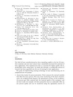
melts. Because of the operating conditions, the sensors for casting process con-
trol, shown in Figure 4.1-1, can be divided into ‘sensors without melt contact’ and
143
4
Sensors for Process Monitoring
Sensors in Manufacturing. Edited by H.K. Tönshoff, I. Inasaki
Copyright © 2001 Wiley-VCH Verlag GmbH
ISBNs: 3-527-29558-5 (Hardcover); 3-527-60002-7 (Electronic)
4 Sensors for Process Monitoring144
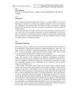
Fig. 4.1-1 Classification of sensors
‘sensors with melt contact’. Further subgroups are distinguished by the particular
control task, the control of the alloy composition, the temperature, the dosage and
current of the melt and solidification. This division deliberately does not distin-
guish with regard to the separate casting processes as many of them do not allow
a general summary without double naming of the sensors and also lack clarity.
In this classification, the physical measuring principle will be a final character-
istic. The control and regulation of these casting parameters determine the quality
of the casting products and the productivity of the foundries.
4.1.1.2 Sensors with Melt Contact
The functional groups of this type of sensor come directly into contact with the
melt or the mold or are separated from the melt by protecting tubes. Normally
the protecting tubes consist of thermodynamic permanent ceramics with high
temperature stability as aluminium melts, for example, have a corrosive effect on
the sensor material. Sensors with melt contact can be divided into types for the
control of the chemical composition, types for the control of the temperature, and
types for the control of the dosage or the level.
4.1.1.2.1 Sensors for Controlling Chemical Characteristics
The gas content, the chemical composition, and the purity of the melt are of deci-
sive significance for the quality of the component. The chemical composition of
the melt determines, in addition to the solidification characteristics of the casting
which are influenced by the grain refining agent above all through the element
content of the alloy, the mechanical properties of the component. The solvent
power of metal melts for gases decreases with decrease in temperatures. Because
of this, evolution of gaseous hydrogen and oxygen which are absorbed from the
atmosphere and dissolved in the metal melts takes place and pores are formed in
the casting. To guarantee a perfect component, the gas content must be controlled
frequently before and during serial casting [5–7].
Partial Pressure Measurement
As hydrogen is the only gas which dissolves in aluminium melts, the hydrogen
content can be simply controlled with the Chapel (continuous hydrogen analysis
by pressure evaluation in liquids) and the Telegas or Alscan process. With the cha-
pel process a porous graphite punch which is connected through a gas-tight cera-
mic tube to a pressure gage will be immersed in the melt and evacuated for a
short time. The graphite punch reacts like a bubble into which the hydrogen dif-
fuses out of the melt until the pressure in the probe and the hydrogen partial
pressure in the melt are the same. If the state of equilibrium is reached the hy-
drogen content of the melt at a constant temperature can be calculated by using
the Sievert laws [6–9]:
log C
H
0:5 log p
H
2
À A=T B 4:1-1
4.1 Casting and Powder Metallurgy 145
where C
H
= concentration of hydrogen dissolved in aluminium, p
H
2
= partial pres-
sure of segregated hydrogen, T=temperature, and A, B=Sievert constants, de-
pending on the alloy composition.
The chapel process is easy to handle, reliable, fast and has been proved espe-
cially in Europe.
Thermal Conductivity Measurement
The Telegas or Alscan method has a ceramic probe below the melt level, out of
which pure inert gas or nitrogen flows continuously into the melt and is then col-
lected in a hood. While the blowholes are rising the dissolved hydrogen diffuses
out of the melt until equilibrium of the gas circulation is reached. The hydrogen
partial pressure is measured with a thermal conductivity-measuring cell [10–12].
The telegas or Al scan method is especially used in the USA. In contrast to the
chapel process, the measurements must be carried out over a longer period, at
least 15 min.
Electromotive Force Measurement
In the steel and copper industry, an electrochemical cell made of ceramic (Figure
4.1-2) is used for determining the oxygen content in the melt [13–16]. The gage
heads contain a thermoelectric couple (see next section) and a voltaic cell which
has a mixture of a metal and an oxide, eg, Cr/CrO, inside with a known oxygen
partial pressure as a reference material.
4 Sensors for Process Monitoring146
Fig. 4.1-2 Electromotive force cell
On immersing the gage head in the melt, an electromotive force between the
reference material and the melt arises because of the oxygen ion conductivity of
the partially stabilized ZrO
2
. The relationship obeys the Nernst law:
E ÀRT=4F ln p
O
2
=p
H
O
2
4:1-2
where E = energy, R=gas constant, T = temperature, F = Faraday constant, and p
O
2
,
p
H
O
2
= partial pressure of oxygen at the two electrodes.
The potential difference as a measure to calculate the oxygen activity of the
melt can be used here. The temperature of the cell is an important factor in the
measurement. A voltaic cell can be used at higher temperatures for the measure-
ment of the oxygen content of solid or liquid metals, slag, and mattes. With this
sensor the hydrogen, magnesium, and sodium contents can be determined when
aluminium is melted [17, 18].
Resistance Measurement
The Liquid Metal Cleanliness Analyzer (LiMCA) is used to control the purity of
the melt continuously. The measuring principle is mainly based on the registra-
tion of very small resistance modifications in the microohm range in liquid alumi-
nium or magnesium caused by non-metallic inclusions. The robust and safe LiM-
CA sensor is used in light metal foundries and consists of a heat-resistant tube
for sampling and two electrodes, one in a test-tube and the other in the surround-
ing melt [5, 19–21].
4.1.1.2.2 Sensors for Controlling Temperature
The temperature of the melt and the mold is of decisive significance for the correct
mold filling and the cycle time of the serial casting, which implies the productivity of
the company. Temperature sensors with melt contact are based on the principle of
conduction, in contrast to the temperature sensors without melt contact. These sen-
sors are also separated by protecting tubes or layers of aggressive melts. There is a
division between thermoelectric couples and resistance pyrometers.
Thermoelectric Couple Measurement
Thermoelectric couples (Figure 4.1-3) are based on the thermoelectric effect (See-
beck effect). They consist of two wires of different metals with the ends soldered
4.1 Casting and Powder Metallurgy 147
Fig. 4.1-3 Structure of a thermoelectric couple
or welded. A voltage arises when the two ends have different temperatures. This
thermoelectric voltage depends on the metals used and on the temperature differ-
ence between the junction point and the connecting point (summing point) of the
measuring instrument. The measurement of the thermoelectric voltage is carried
out using high-resistance voltage measuring instruments. If necessary, possible
disturbing secondary thermal effects at supplying parts must be eliminated
through calibration lines. The measuring range is between –200 and 25008C de-
pending on the metals. The following metal pairs are used: platinum/platinum
rhodium, nickel/chrome nickel, iron/constantan, and copper/constantan [9, 22,
23].
Thermoelectric couples can also be produced without a protecting tube in very
small sizes with a minimum diameter up to 0.5 mm and a free choice of the
length. These so-called sheath thermoelectric couples are the most commonly
used temperature sensors in light metal foundries because of their flexibility and
reasonable price.
Resistance Pyrometer Measurement
The resistance pyrometer is based on the principle of a change in the electrical re-
sistance with variation in the temperature of a conductor or semiconductor. De-
pending on the predominant electrical conducting mechanism, a difference is
made between pyrometers with a positive (metals) and a negative (high-tempera-
ture conductors, negative temperature coefficient resistors, thermistors) resistance-
temperature characteristic curve. Resistance pyrometers require analog or digital
electrical connections for measurement and for higher demands measuring
bridges and compensators are used. Similar to the thermoelectric couple, the ad-
vantages of these sensors are the reasonable price, the robustness, the flexibility,
and the simple handling.
4.1.1.2.3 Sensors for Controlling the Dosage/Level
A correct dosage is decisive for quasi-stationary thermal economy of the mold and
therefore significant for the quality of the casting. By reducing the cycle material
the economy of the foundry is favored [24].
Contact Electrode Measurement
The easiest and most common way to control the dosage is realized with a con-
tact electrode. When the melt touches the contact electrode a signal will be sent to
the installation control which controls the dosage process [25, 26].
Inductive Sensing
In light metal furnaces, inductive level sensors which are protected from the melt
by suitable austenitic or ceramic protecting tubes are used to control the level con-
tinuously. This principle is based on an induced voltage in a conducting loop in
the sensor. This voltage causes an electric current which forms a magnetic field
around the sensor. A signal is originated by the variation of the magnetic field by
4 Sensors for Process Monitoring148
the melt [27]. This type of level sensor is expensive, susceptible to wear and costly
in maintenance.
4.1.1.3 Sensors without Melt Contact
The physical measuring methods and the technical realization of this kind of sen-
sors are relatively complicated and complex, although necessary in order to guar-
antee continuous production and quality assurance. Since these sensors do not
touch the melt, which is often chemically aggressive, and since they are not ex-
posed to high thermal stresses, it is unlikely that they will fail. Sensors without
melt contact can be divided into different types: sensors for controlling the cur-
rent and solidification, for controlling the temperature, for controlling the dosage,
pressure, level, and route.
4.1.1.3.1 Sensors for Controlling Current and Solidification
Precise knowledge of the melt current, the solidification and the thermal econo-
my of the mold is an important factor in the design of casting dies. With this
knowledge it is possible to attain perfect heating and cooling circuits, cycle times,
and temperature distribution for directional solidification. For the continuous cast-
ing process the control of the position of the solidification contour is of great im-
portance since the continuous cast velocity and the charging depend on this posi-
tion. If the meniscus is not respected, liquid metal may flow over or run out [28–
30].
X-ray Imaging
X-rays from a radioactive source, typically a rod-type emitter (eg, Co-60) in a lead
protector, radiograph the mold. Since solid metals absorb X-rays better than melts
owing to their higher density, the position of the solidification contour can be de-
tected by a scintillation meter. The sprue, ie, the melt current during die casting,
can be supervised and the position of the solidification contour can be directed in
a continuous casting mold. Figure 4.1-4 shows a schematic diagram of this super-
vising method for continuous casting [30–35].
The complex protection of the workplace against radioactive radiation reduces
the number of applications of this supervising method. X-ray processes and com-
puted tomography (CT) are additionally used for nondestructive component test-
ing and for the quality testing of safety components. Defects in casting, eg, inclu-
sions, sink-holes, pores, cracks, etc., can be detected [37, 38].
4.1 Casting and Powder Metallurgy 149
Thermal Imaging
Cameras for thermal imaging visualize infrared radiation, ie, thermal radiation
from object surfaces. Since the atmosphere is not transparent to thermal radiation
over the whole radiation spectrum, these cameras are divided into near-, medium-
and far-infrared cameras according to the sensitivity of their sensors [29, 30]. The
flow of metal melts is examined for model molds consisting of a solid mold with
die sinking and even face and which is closed by a moveable, transparent mold
half of solid foam (aerogel) (Figure 4.1-5). Owing to its transparency to visible
light and thermal radiation in the near-infrared range, the flow and solidification
of steel, lead, aluminium, and magnesium melts, etc., can be observed [29, 39].
Since the assembly is complex and the use of the aerogel slab is difficult, ther-
mal imaging for the examination of the flow of melts is only used in research or
for the design of molds.
4.1.1.3.2 Sensors for Controlling Temperature
If the metallurgical melt flow is correct, up to 100% of rejects in die casting can
occur owing to the wrong temperature of the mold. Non-contact temperature sen-
sors permit a correct mold design and effective continuous control of the melt
temperature at positions difficult to access or at temperatures that destroy contact
sensors [40].
4 Sensors for Process Monitoring150
Fig. 4.1-4 Principle of X-ray imaging
4.1 Casting and Powder Metallurgy 151
Fig. 4.1-5 Filling of a model mold
Thermal Imaging
For thermal imaging of the mold temperature, as shown in Figure 4.1-6, mainly
far-infrared cameras are used due to the emission spectrum [29, 41]. With these
examinations a relationship between the die casting temperature, the flow tem-
perature of the cooling system, and the cast cavity could be found [40]. Further,
thermal imaging is used for the verification of simulation results and mold de-
signs [41, 42].
Another application of this type of camera is the supervision of the cast tem-
perature for continuous casting. Additionally, conventional cameras are used for
the observation of the billet surface, the billet orientation, etc. [43].
Pyrometry
Pyrometry is based on the same physical rules of thermal radiation and thermal
imaging. In contrast to thermal imaging cameras, pyrometers detect the tempera-
ture only at intervals, but they are more economical, easier to use, and they have
an excellent accuracy of up to ±1%. In general, foundries use total radiation py-
rometers for low temperatures and ratio or two-color pyrometers for higher tem-
peratures as emitted by iron and steel melts. Total radiation pyrometers can easy
be tested as their signals are directly subject to the Stefan-Boltzmann law. For the
two-color pyrometer two partial radiations in different wave ranges are considered.
Ratio pyrometers measure the temperature of the object by the ratio of the radia-
tion density of two different spectral regions. The advantage is that the transmis-
sion distance does not influence the measuring results [31, 44, 45].
In the steel industry, pyrometers have been used since the 1950s for the super-
vision of melt temperatures [31, 46]. Additionally, they are used for continuous
casting for the control of the billet temperature, ie, for the control of the cooling
system [47].
4 Sensors for Process Monitoring152
Fig. 4.1-6 Thermogram of a model mold
Magnetic Field Measurement
Magnetic field measurement is used for the high-precision heating of thixo billets.
For this die casting process the cast material, the so-called thixo billet, is in a
range between the solidus and liquidus temperatures, ie, the material is partly sol-
id and partly liquid. This thixotropic state causes a change in the magnetic field
which can be measured by a field-measuring sensor to an accuracy of down to
0.5% [48, 49]. This complex measuring process, which has to be calibrated for
every alloy composition, is used over the whole cross-section of the thixo billet be-
cause of the highly required even distribution and measurement of the tempera-
ture.
4.1.1.3.3 Sensors for Controlling Dosage, Pressure, Level, and Route
The physical measuring method of this type of sensor is often the same so that it
seems reasonable to combine these process parameters into one control group.
Sensors in this group are mainly used for the supervision of die casting which, in
spite of a more frequent use of sensors, is still called ‘black box technology’.
Further applications are continuous casting and break-mold casting [50, 51].
Pneumatic Sensing
Important machine parameters of die casting are the injection shot velocity and
the pressure. The pressure is supervised by pneumatic sensors in the hydraulic
system of the die casting machine. Pneumatic sensors are also used in the fur-
nace gas chamber of dosage furnaces which have shown a high degree of reliability
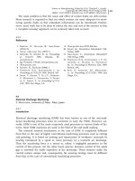
in the aluminium industry (Figure 4.1-7) [41, 52, 53].
Another application of pneumatic sensing is level measurement in dosage or
blast furnaces. Figure 4.1-8 shows the functional principle of this sensor, which
measures the pressure necessary for the exhaust of nitrogen bubbles from a cera-
mic tube on the bottom of the melting pot [54].
4.1 Casting and Powder Metallurgy 153
Fig. 4.1-7 Dosage furnace
For these control types, conventional pressure gages are used which are subject
to the pneumatic or hydrostatic principle.
Displacement Transducer
The control of the injection shot velocity in die casting is the essential criterion
for turbulence-free filling and therefore for components with only a few pores.
The injection shot velocity is controlled in three phases depending on the piston
displacement. Magnetic displacement transducers measure the piston position.
The principle of this type of sensor is based on the influence of magnetic effects
(eg, the Hall effect) which depend on the displacement [55]. The sensors are
maintenance-free and extremely robust.
Acceleration Meter
In order to avoid the adhesion of the billet to the mold in continuous casting and
to assure a clean billet surface, the continuous cast mold is set in an oscillating
motion, vertical to the billet. This oscillation is supervised by seismic acceleration
meters which represent a mass-spring damping system. The system consists of
an inert seismic plate, a spring with a force proportional to the displacement and
a damping component proportional to the velocity [22, 56, 57].
4.1.1.3.4 Eddy Current Sensing
Eddy current measurements represent another solution for the supervision of the
level in a mold in the continuous casting process (Figure 4.1-9). According to Qui
[58], the detection of sullage which must not enter the mold is another applica-
tion when liquid steel is filled from the ladle into the tundish [59–61]. The chang-
ing level of the steel bath influences the number and course of the eddy current
in liquid steel and the surrounding conductive objects. The resulting change in
the electromagnetic field is measured [62].
4 Sensors for Process Monitoring154
Fig. 4.1-8 Level measurement in a blast furnace [54]
Force Sensing
The most conventional way to measure the level continuously is furnace weighing
with maintenance-free electronic load cells. In general, the level is indicated di-
rectly at the furnace by means of a signal lamp (see Figure 4.1-7) or it is indicated
to the master computer. The load cell is cheap, maintenance-free and can be used
for general purposes. Charging appliances are equipped with the same systems
for balancing the material [63–66].
These load cells are based on the physical principle of piezoelectric force sens-
ing technology (Figure 4.1 10). When force is exerted on a piezoelectric crystal
(eg, quartz, barium titanate (BaTiO
3
)), negative crystal lattice points are offset
against positive ones so that a difference in charge can be measured at the crystal
surfaces as a function of force [22].
The function of sensors for the measurement of the internal pressure in cast-
ing chambers is subject to the same physical principle. With the measurement of
the pressure development, important knowledge about the melt flow, mold filling
and solidification during the filling process is achieved [67– 69].
4.1 Casting and Powder Metallurgy 155
Fig. 4.1-9 Principle of
eddy current sensing
Fig. 4.1-10 Schematic
diagram of a piezo-
electric force gauge
Laser Level Measurement
Laser sensors are used for the measurement of the meniscus in the continuous
cast process and for level control of the launder and the sprue in automatic break-
mold casting methods of aluminium and steel (Figure 4.1-11) [4, 70–73].
In laser level measurement, an emitter gives short light impulses at a high fre-
quency (approximately 10 Hz) in the direction of the metal bath surface. From
there a small proportion is reflected and sensed by a receiver. The transit time is
a measure of the level [51].
Camera Level Measurement
Another system for level measurement in molding boxes works with a camera
and secondary image processing so that the stopper control can keep the menis-
cus in the sprue at a constant level (Figure 4.1-12) [2, 74].
4 Sensors for Process Monitoring156
Fig. 4.1-11 Principle of laser level measurement
Fig. 4.1-12 Principle of camera level measurement
The cast behavior of types with many cores which in general differs widely de-
pending on the mold can be limited by level control and the high requirements to
achieve a constant hydrostatic pressure in the sprue can be fulfilled [74].
4.1.1.4 Summary
The quality of the casting and the productivity of a foundry depend on few but
very important parameters which are difficult to control. This is mainly due to the
fast dynamic processes during filling and solidification and to the sophisticated
conditions in the foundries. The sensors specifically adapted to these require-
ments for the control of the chemical and physical properties of the melt and the
perfect control of the machine and mold parameters such as cast velocity, pres-
sure, and temperature allow optimum casting conditions. A sophisticated sensor
technology creates the conditions for integral process control of automated casting
processes, eg, die casting, which is still considered to be ‘black box technology’.
This sensor technology makes the integration of the casting process into produc-
tion lines and CIM systems possible.
4.1 Casting and Powder Metallurgy 157
4.1.1.5
References
1 Kahn, F., Giesserei 80 (1993) 579–584.
2 Nacke, B., Kessler, M., Andree, W., Elek-
towärme Int., Ed. B (1995) 138–143.
3 Stoltenberg, K., Röhrig, K., Giesserei-
Praxis 80 (1993) 52–56.
4 Mezger, F., Giesserei 82 (1995) 332–335.
5 Lessiter, M. J., Rasmussen, W. M., Mod.
Casting 86 (2) (1996) 45–48.
6 Eigenfeld, K., Wechselberger, O.,
Knoche, D., Aluminium 74 (1998) 244–
247.
7 Eigenfeld, K., Wechselberger, O.,
Schaan, Knoche, D., Giesserei 84 (1997)
45–47.
8 Nolte, M., Giesserei 86 (1999) 72–75, 77–
80, 83.
9 Hasse, S., Giessereilexikon; Berlin: Schiele
& Schön, 1997.
10 Chen, X.G., Klinkenberg, F. J., Engler,
S., Heusler, L., Schneider, W., J. Miner.
Met. Mater. Soc. 46 (8) (1994) 34–38.
11 Neff, D. V., in: Proceedings of the 3rd Inter-
national Conference on Molten Aluminium
Processing, Orlando, FL; 1992, pp. 387–405.
12 Dasgupta, S., Apelian, D., Molten Alumi-
nium Processing, 5th International AFS Con-
ference, Orlando, FL; 1998, pp. 233–258.
13 Seetharaman, S., Sichen, D., Jakobsson,
A., Sens. Model. Mater. Process. (1997) 327–
344.
14 Sauerstoff-Messanlage Deltatherm III; Kün-
zer, 1993.
15 Yajima, T., Koide, K., Takai, H., Fukatsu,
N., Iwahara, H., in: Proceedings of the
20th Commemorative Symposium on Solid
State Ionics in Japan; 1995, pp. 333–337.
16 Dekeyser, J. C., Schutter, F. D., Poorten,
C., Van der Zhang, L., Fray, D. J., in: Pro-
ceedings of the 5th International Meeting on
Chemical Sensors; 1995, pp. 273–275.
17 Fergus, J. W., Giesserei-Praxis 85 (1998)
443.
18 Vangrunderbeek, J., Lens, P., Castelijns,
C., Verstreken, P., Light Met. (1999)
1005–1009.
19 Bussmann, W., in: Symposium der
Deutschen Gesellschaft für Materialkunde;
1995, pp. 189–197.
20 Dupuis, C., Dallaire, F., Maltais, B., in:
128th TMS Annual Meeting, ‘Light Metals
1999’, Warrendale, PA; 1999, pp. 1069–
1077.
4 Sensors for Process Monitoring158
21 Carozza, C., Lenard, P., Sankaranaraya-
nan, R., Guthrie, R.I.L., in: Proceedings
of the International Symposium, 36th An-
nual Conference of Metallurgists of CIM;
1997, pp. 185–196.
22 Beitz, W., Küttner, K. H., Taschenbuch für
den Maschinenbau; Berlin; Springer, 1995.
23 Beckerath, A., Sens. Rep. 4 (2) (1989) 6–10.
24 Lindner, P., VDI-Fortschr Ber. 5, No. 582
(2000).
25 Malpohl, K., CP+T 15 (3) (1999) 8–12, 14.
26 Krause, H., Schiebold, K., Nielebock,
E., Obieglo, B., Giessereitechnik 36 (1990)
19–20.
27 Füllstandsmesseinrichtungen; Wiehl-Biel-
stein: Carli Electro Automation, 1999.
28 Haferkamp, H., Bach, Fr W., Niemeyer,
M., Viets, R., Aluminium 75 (1999) 945,
947–953.
29 Haferkamp, H., Bach, F W., Niemeyer,
M., Viets, R., Weber, J., Breuer, M.,
Kruessel, T., in: Proceedings of the IEEE
International Symposium on Industrial Elec-
tronics; 1999, pp. 1442–1447,
30 Regusewicz, F., Arbeitskr. Aluminium-
Automobil (10) (1998) 151, 153–168.
31 Peacock, G.R., Proc. SPIE (1999) 171–189.
32 Fitting, D.W., Dubé, W.P., Siewert, T. A.,
Paran, J., Review of Progress in Quantitative
Nondestructive Evaluation; New York: Ple-
num Press, 1995, pp. 2315–2321.
33 Chun, J. H., Hytros, M.M., Jureidini, I.
M., Saka, N., Lanza, R.C., Ann. CIRP
(1999) 147–150.
34 Hytros, M. M., Chun, J. H., Lanza, R. C.,
Saka, N., J. Manuf. Sci. Eng., Trans.
ASME (1998) 515–522.
35 Dumitriu, B., Mitut, R., Bretthauer,
G., Garbe, J., Automatisierungstechnik
(839) (1997) 66–80.
36 Dumitriu, B., Mikut, R., Bretthauer,
G., Werfel, G., Böttger, S., Stahl Eisen
119 (1999) 35–38.
37 Schmitz, V., Reiter, H., Ing Werkst. 4 (8)
(1999) 43–45.
38 Kroth, E., Giesserei 85 (6) (1998) 35–38.
39 Haferkamp, H., Niemeyer, M., Pelz, C.,
Viets, R., Schaper, M., Proc. SPIE 3700
(1999) 164–170.
40 Giesserei 80 (1993) 451–456.
41 Muller, W., Feikus, F., Trans. Am. Foun-
dry men’s Soc. 104 (1996) 1111–1117.
42 Jaerke, P., Eigenfeld, K., Giesserei 74
(1987) 713–717.
43 Aigner, H., Angerer, R., Reisinger, J.,
Berg- Hüttenmänn. Monatsh. (140) (1995)
156–161.
44 Glueckert, U., Erfassung und Messung
von Wärmestrahlung; Franzis-Verlag, 1992.
45 Elektro (22) (1991) 58–60.
46 Wanin, M., in: Proceedings of the 3rd Euro-
pean Conference on Advanced Materials and
Processes, Part 2; 1993.
47 Lasday, S. B., Ind. Heating 60 (12)
(1993) 36–38.
48 Juergens, R., Graeft, T., Gies, J., in:
Thermprocess Symposium; 1999, pp. 45–61.
49 Graeft, T., Juergens, R., Elektrowärme
Int. Ed. B 57 (B2) (1999) 69–73.
50 Qual. Today (1995) 50, 52.
51 Krueger, G., Sens Technol. Anwendung
509 (1984) 243–248.
52 Malpohl, K., Casting Plant Technol. 15 (3)
(1999) p. 8–10, 14.
53 Croom, D. E., Foundryman 89 (1996) 440–
445.
54 Danloy, G., Stolz, C., Crahay, J., Du-
bois, P., in: 58th Ironmaker Conference
Proceedings; 1999, pp. 89–98.
55 Sjögren, B., Fitze, R., Giesserei 83 (16)
(1996) 92, 94, 96.
56 Chumakov, S.M., Sorokin, A. N., Steel
USSR 28 (6) (1998) 27–29.
57 Miller, G., Stahl Eisen 111, (12) (1991)
73–78.
58 Qui, D., Scand. J. Metall. (1997) 178–182.
59 Ind. Heating (1993) 36–38.
60 Klein, A., Wolf, M., Comprehensive Ma-
chine and Process Condition Monitoring in
Conventional Continuous Casting; Iron and
Steel Society, 1992, pp. 807–815.
61 Martin, J.F., Dusser, H., Nadif, M.,
Steel Technol. Int. 13 (1995) 183–185.
62 Rohac, J., Pisoft, V., Stahl Eisen 112 (3)
(1992) 89–91.
63 Braunger, H.P., Hann, R., Giesserei 77
(3) (1990) 75–78.
64 Shingledecker, F., Diecasting Eng. 38 (4)
(1994) 22, 24.
65 Giesserei-Erfahrungsaustausch 42 (1998) 546.
66 Giesserei-Erfahrungsaustausch 38 (1994)
321–322.
67 Kangas, S., Fritsche, S., Diecasting Eng.
43 (3), 38, 40, 42, 44–45.
68 Giesserei 83 (15) (1996) 37–38.
4.1 Casting and Powder-metallurgy 159
69 Niu, X.P., Tong, K.K., Hu, B. H., Pin-
will, I., Int. J. Cast Met. Res. 11
(1998) 105–112.
70 Aluminium 76 (2000) 281–282.
71 Johansson, S., Lowback, G., Sensors 13
(8) (1996) 34–36.
72 Johansson, S., Ind. Heating 63 (9) (1996)
89–91.
73 Smith, J. R., Foundry Trade J. 166
(1992) 536, 538–539.
74 Nacke, B., VDI-Ges. Energietech. 1292
(1997) 299–313.
4.1.2
Powder Metallurgy
R. Wertheim, ISCAR Ltd., Hardmetal Industrial Products, Tefen, Israel
4.1.2.1 Introduction
Powder metallurgy (PM) is a metal processing technology in which metal pow-
ders are used to produce technological parts. It is an important commercial tech-
nology for the mass production of near-net shapes, eliminating or reducing the
need for further machining processes. Certain metals or alloy combinations which
cannot be produced by other methods can be formed by PM and sintering.
In the various PM manufacturing sequences, the powders are compressed into
desired shapes, injected into molds or extruded through a nozzle to produce long-
er parts and profiles. After being shaped, the so-called ‘green’ product is heated to
cause bonding of the particles into a hard, rigid mass.
Compression by pressing, injection molding, or extrusion is accomplished with
suitable equipment using tools or molds designed specifically for the parts to be
manufactured. The tooling, in pressing, consists of a die and at least one punch;
in injection molding, of a die and a nozzle; and in extrusion, of die and injection
equipment.
The green, very brittle product is transformed into a very hard part by sintering
at a temperature below the melting point of the metal.
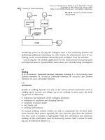
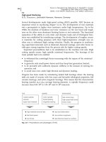
Figure 4.1-13 shows the four main conventional steps to produce metal parts
after the metallic or ceramic powders have been produced: (A) the blending and
mixing of the powder to the required particle size and various chemical composi-
tions; (B) the compacting, in which the powder is pressed into the desired shape;
(C) the sintering to the final or almost final size and shape; and (D) further possi-
ble steps: grinding, finishing, and coating.
In the following explanation, the use of monitoring, control, and sensors in the
production of mainly hardmetal products made of carbides, nitrides, and oxides
mixed with a suitable binder such as Co or Ni will be discussed.
4.1.2.2 Mixing and Blending of Metal Powders
The properties of the powder compound, the preparation and composition of the
powder mix, and the shaping process are of significant importance in the produc-
tion and performance of hardmetal products.
Figure 4.1-14, for example, shows a flow chart of the basic mixing procedure for
the various shaping processes in the production of carbide cutting tools. In the
simplest hardmetal composition, the basic mixture consists of tungsten carbide
(WC) powder of a specified particle size and size distribution and cobalt (Co) pow-
der; if necessary, addition of carbon black powder is used to correct the carbon
content of the hardmetal. In order to determine the final hardmetal properties, cu-
bic carbides of titanium (TiC), tantalum (TaC) and/or niobium (NbC) may be
added to the mix or in the prealloyed form with the tungsten carbide. The name
hardmetal is basically applied to all hard metallic materials, but in a narrower
sense it is mainly associated with the above combinations of hard, distinctly brit-
tle, metallic materials and a relatively soft ductile metal, predominantly from the
iron group (Fe, Co, Ni), the so-called binder or binder metals. These binder me-
tals (mainly Co) may be present in different amounts in a mixed crystal form in
the binder phase.
For the subsequent wet milling, the required milling liquid, such as an alcohol,
acetone, hexane, or other organic liquid, is added to the mixture. The purpose of
the milling liquid is to protect the components of the mix from oxidation and also
to insure optimum dispersion of the ingredients.
Powder milling is a crucial step, since adequate size reduction coupled with
uniform distribution of all the ingredients can have a decisive effect on the sinter-
ing behavior. For wet milling, attritors or ball mills are used. In the stationary
water-cooled container a stirrer rotates, giving a rotary motion to the milling medi-
um, the charge, and the milling liquid. By means of a pumping system, the sus-
pension being milled is circulated in order to insure uniform milling.
After milling, the suspension is sieved and dried for the next step. Depending
on the subsequent forming process, a suitable procedure is selected as indicated
in Figure 4.1-14.
The selected process or criteria depend on the specific requirements of the pre-
pared powder. Therefore, for example, the powder mix for dry pressing or injec-
tion molding has to be brought into a granular form which has good flow proper-
ties, constant fill density, and a suitable granule size.
4 Sensors for Process Monitoring160
Particle Condition
Upper
punch
Die
Lower
punch
F
F
As
sintered
product
Grinding
wheel
Finished
product
(B) Compacting
(C) Sintering
(D) Grinding
Mixer
(A) Blending
Fig. 4.1-13 The conventional powder metallurgy production sequence: (A) blending or mixing;
(B) compacting; (C) sintering; (D) grinding [1]
The material from the wet milling process, consisting of powder mix, milling
liquid, and dissolved or dispersed pressing lubricant, is processed by granulation
or spray drying, into powder or powder mix. During spray drying, the suspension
is forced from the pressurized container and atomized in a hot gas stream in the
spray tower. This atomization results in the formation of spherical granules of
variable diameter, eg, from a few micrometers to 200 lm.
4.1.2.2.1 Monitoring and Sensors in Powder Production
Monitoring the hardmetal powder includes the particle size, shape, distribution,
and surface area. Features such as friction, flow or packing, composition, homoge-
neity, and contamination are essential for the subsequent compacting and sinter-
ing processes.
Determination of particle size by the evaluation of one of the geometric parame-
ter depends on the shape, which can be spherical, flake, or irregular. The use of
microscopy measurement techniques, such as optical, scanning electron, or trans-
mission electron microscopy, are the most common sensors.
Screening is also used in obtaining sized powders. It provides a means for re-
moving specific size fractions. The use of these methods is applicable for larger
grain sizes and requires long screening durations.
Particle size analysis by sedimentation is mostly applicable to the smaller sizes.
Particles settling in a liquid like water or air sensor device reach a terminal veloc-
ity dependent on both the particle size and the fluid velocity [3].
Size analysis by sedimentation uses a predetermined settling height and places
a dispersed powder at the top of a tube. The amount of powder settling at the bot-
tom (as a function of time) allows the calculation of particle size distribution. Ob-
4.1 Casting and Powder Metallurgy 161
TUNGSTEN CARBIDE BINDER METALS OTHER CARBIDES
NiCoWC
TaC,NbC, TiC, Mo
2C, VC, Cr3C2
Mixing
Wet Milling
Wet Sieving
HM Granulate
Compacting\Pressing
Injection Molding
Spray Drying Granulation
Pressing Lubricant
Plasticiser
Vacuum Drying
Kneading
HM Kneaded
Material
Extrusion
Vacuum Drying
Sieving
HM Powder
Cold Isostatic
Pressing
Fig. 4.1-14 Flow chart showing the preparation of carbide powder mix for various shaping pro-
cesses [2]
viously, the fastest settling particles are the largest whilst the smallest can take a
considerable time to settle. Sensors and automatic instrumentation for perform-
ing sedimentation and separation can use gravity forces or centrifugal force de-
vices, light blocking, or X-ray attenuation methods.
Air classification sensors achieve a separation of powders into selected size frac-
tions using a cyclone or a spinning disk and cross-current airflow.
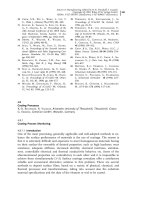
For automatic sensing of particle size, a low-angle Frauenhofer light scattering
system using monochromatic (laser) light is used (Figure 4.1-15). Intensity and
angular extent are affected by the particle sizes passing in front of the photo-
diode-array detector. A computer providing the particle-size distribution analyzes
the data. An electrical conductivity-sensing device provides another option for
measuring the number and size of particles suspended in the fluid. Conductivity
measurement is achieved by making the fluid conductive and applying a small
voltage across an opening.
A light-blocking sensor based on a light cell and a photocell is also used to deter-
mine particle size. The amount of light blockage due to the light beam interruption
by moving particles is detected by the photocell, indicating particle-size distribution.
A large number of other sensors are used in the powder production steps, eg,
mixing, blending, or spray drying. Most of these are not built into the production
sequence itself to provide a direct feedback signal, but are mainly used as mea-
surement sensors in open-looped systems.
4.1.2.3 Compacting of Metal Powders
Compacting of powders before sintering can be performed to give a low- or high-
density component, or simultaneous pressing and sintering can be used to give
the final product. Powders with good sintering densification can be shaped using
low pressures as used in some compacting applications and in the injection mold-
ing process. During compacting, the powder is deformed into a high-density com-
4 Sensors for Process Monitoring162
Laser
Incident
beam
Sample
cell
Scattered
beam
Lens
Powder
feed
Photodiode
array
detector
Computer
Amplifier
Fig. 4.1-15 Sensor based on a photodiode detector to analyze powder-particle size [3]
ponent that approaches the final geometry. The means of delivering the high pres-
sure to the powder, the mechanical constraints, the powder properties, and the
rate of applying pressure are the main parameters determining the density which
are analyzed during the process.
Conventional compacting of powder is normally performed with the pressure
applied along one axis as shown in Figure 4.1-16. The steps during the pressing
cycle start by filling the die with a very precise amount of powder which is con-
trolled by the movement of the feeder shoe.
The lower punch position during filling determines the required volume. After
filling the cavity, the lower punch drops to the pressing position and the upper
punch is brought into the die. Both punches are moved and loaded to generate
stress within the powder mass. At the end of the movement, the powder com-
pound experiences the maximum stress. Finally, the upper punch is removed and
the lower punch is moved upwardly to eject the compact.
In Figure 4.1-16, the pressure is transmitted from both the top and bottom
punches. Alternatively, a single-action pressing can be performed when pressure
is transmitted from only one punch. The applied pressure results from the punch
movement forming a smaller volume of the powder particles and causing a de-
crease in pore space. During pressing, more particles are in contact with each
other and the density is higher up to a very specific required value as shown in
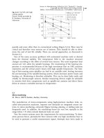
Figure 4.1-17. As shown, the initial rate of densification with the compacting pres-
sure is high. With continued deformation the slope of the powder density versus
pressure curve declines, reflecting work hardening. At the onset of the compact-
ing cycle (1), voids exist between the particles. With increased pressure better
packing and decreased porosity are achieved. The worked part following pressing
(3) is defined as a ‘green compact’, which indicates that it has not been fully pro-
cessed. The green density is much greater than the starting bulk density, which
gives adequate strength for handling.
4.1 Casting and Powder Metallurgy 163
V. F
V. F
(3)
V. F
F
(2)
(1)
Lower
punch
Die
Feeder
shoe
Powder
Upper
punch
v
V
V
(4)
Fig. 4.1-16 Pressing powders: (1) filling the die cavity with powder; (2) initial and (3) final posi-
tions of upper and lower punches during compacting; (4) ejection part
4.1.2.3.1 Compacting Equipment
Presses used in conventional PM compacting are mechanical, hydraulic, or a com-
bination of the two. Because of differences in part complexity, presses can be dis-
tinguished as pressing from one direction, referred to as single-action presses; or
pressing from two directions, which can be either a double or multiple action.
Current available press technology can provide up to 10 separate action controls
to produce complex geometric parts.
Figure 4.1-18 shows a typical pressing setup with a controlled process. The sys-
tem shown is used for double-action pressing of carbide inserts for cutting tools.
The positioning of the upper and lower punches is adjusted according to the re-
quired powder volume and the compacting ratio. A computer that records and op-
timizes the process parameters is connected to the compacting system.
4 Sensors for Process Monitoring164
True density
100%
50%
0%
0
(1)
(2)
(3)
Compacting pressure
(2) (3)
(1)
Fig. 4.1-17 Effect of applied pressure during compacting on the density: (1) initial powders after
filling; (2) repacking; (3) compacting of particles [1]
Fig. 4.1-18 Pressing setup with a controlled process and an automatic handling system
4.1.2.3.2 Sensors and Control
In compacting, the pressed height is determined by the powder fill and the com-
pacting pressure. To maintain control of the final compact height and shape, both
the apparent and final densities must be known. To achieve more uniform density
of the pressed compact, the double-action pressing system is used.
Figure 4.1-19 shows a scheme of a controlled pressing system in which the low-
er punch can be adjusted according to the required filling height. The filling
height or volume is reduced during pressing to the required size, which corre-
sponds to the green density, and the final component size after sintering. A high
green density normally results in improved final properties. However, as the com-
pacting pressure increases, the mechanical locking of the component in the die
cavity also increases. Thus, the ejection forces increase with increasing compact-
ing pressures.
If mechanical motions taken off a cam system deliver the pressure, then the
compact dimensions are the main controlled parameters. Any variations in the
powder fill create small-density variations between parts. Generally, if the pressure
is delivered from a hydraulic source, the pressing is usually slower than when
using a mechanical pressing system. The most important controlled variable to
maintain high accuracy is the force or pressure value. This can be implemented
by using a force sensor in both the mechanical and hydraulic presses. The con-
troller analyzes the maximum force developed in each compacting step and de-
cides accordingly the quality of the part and adjustment of the filling up position.
4.1 Casting and Powder Metallurgy 165
COMMAND
POSITION
SERVO
VALVE
AXIAL
MOVEMENT
UPPER
PUNCH
FILLING
SHOE
HEIGHT
ADJUSTMENT
CONTROLLER
POSITIONING
SENSOR
PRESSURE
SENSOR
DIE
LOWER
PUNCH
POSITIONING
SENSOR
Fig. 4.1-19 Typical pressing system with sensors for punch positioning and pressing pressure
The use of strain-gage sensors, load cells, pressure transducers, piezoelectric cells
or similar devices are used as sensors for the force-controlling system.
High-precision positioning of punches is done, for example, with an optical NC
linear encoder with a resolution of up to 1 lm. The positioning sensor provides
the signal to the controller which decides the command level transferred to the
servo valve. New presses are equipped with proportionally controlled electric mo-
tors as a basis for high-precision compacting. A special capacity sensor is used to
detect the absence of powder in the filling system to avoid damage due to lack of
powder in the feeding system. All data related to pressure and punch positioning
are processed in a computer in accordance with the known density and power
properties.
4.1.2.4 The Sintering Process
In the sequence of the individual production steps shown in Figures 4.1-13 and
4.1-14, from raw material to the finished hardmetal product, the sintering opera-
tion is the process that confers the mechanical, physical, and chemical properties
of the material. These properties are of essential importance for real applications.
The sintering process therefore plays one of the most important parts in the man-
ufacture of components, and determines the hardness, strength, and dimensional
accuracy of the products.
Sintering is basically a heat treatment and a metallurgical process performed on
the compact to bond the metallic particles, thereby increasing strength and hard-
ness.
During this process, the loosely bound powder aggregates after pressing be-
come denser through a change in position of the arrangement and structure of
the atoms. From this, it is clear that the sintering process is the sum of the pre-
dominantly physical processes, which results in the complete or almost complete
filling of the pores. Where the powder mixture is composed of different elements,
the process leads to a material structure which is almost completely expressed by
the appropriate phase diagram. Sintering of hardmetal is composed of multiple
steps, which are dependent on temperature, time, and other influencing factors.
There is no simple rule which can describe the complete process. However, the
technical literature includes sintering equations, expressed in the form of relation-
ships which describe by simple mathematical forms the dependence of the final
material properties or the volume of pores on production parameters, such as
density of the pressed body, the sintering temperature, or the time of sintering.
Material transport mechanisms can include solid-phase sintering of homoge-
neous or heterogeneous powder and liquid-phase sintering. The predominant pro-
cess in sintering hardmetal is permanent liquid-phase sintering, which means
that liquid is present during practically the whole process of isothermal sintering.
On the other hand, in most of the sintering processes of hardmetal, the final
stage of the treatment is usually carried out at temperatures between 0.7 and 0.9
times the binder metal’s melting point. In this case, the terms solid-state sintering
or solid-phase sintering can be used because the binder metal remains unmelted at
4 Sensors for Process Monitoring166
these temperatures. The green compact consists of many distinct particles, each
with its own individual surface, and so the total surface area is very high. Under
the influence of heat, the surface area is reduced through the formation and
growth of bonds between the particles, with associated reduction in surface en-
ergy. The finer the initial powder size, the higher is the total surface area and the
greater the driving force behind the process to provide higher strength.
Figure 4.1-20 shows on a microscopic scale the changes that occur during sin-
tering of metallic powders. Sintering involves mass transport to create the necks
and transform them into grain boundaries. The principal mechanism by which
this occurs is diffusion; other possible mechanisms include plastic flow. Shrink-
age occurs during sintering as a result of pore-size reduction. This depends to a
large extent on the density of the green compact, which is dependent on the pres-
sure during compaction. Shrinkage is generally predictable when processing con-
ditions are closely controlled.
4.1.2.4.1 Sintering Furnaces
Various types of sintering equipment are available. Continuous furnaces, vacuum
batch-type furnaces, and hot isostatic pressing (HIP) equipment are used in the
PM industry.
For PM applications with medium-to-high production rates, the sintering fur-
naces are designed with mechanized flow-through capability for the workparts
shown schematically in Figure 4.1-21.
The heat treatment consists of three steps accomplished in three consecutive
chambers. The three main steps in these continuous furnaces are (1) preheating,
in which lubricants and binders are burned off, (2) sintering, and (3) cooling. The
treatment is illustrated also in Figure 4.1-21 showing schematically also the sinter-
ing temperatures as a function of time or position in the furnace.
In modern sintering practice, various sensors control the atmosphere in the fur-
nace. The purposes of a controlled atmosphere are to (1) protect from oxidation,
(2) provide a reducing atmosphere to remove existing oxides, (3) provide a carbon-
izing atmosphere, and (4) assist in removing lubricants and binders used in press-
ing. Common sintering furnace atmospheres are inert gas, nitrogen based, disso-
4.1 Casting and Powder Metallurgy 167
(1) (2) (3) (4)
Point
bonding
Necks
Pores
Grain
boundary
Pore
Fig. 4.1-20 Sintering on a microscopic scale: (1) bonding of particles at contact points; (2) con-
tact points grow into ‘necks’; (3) reduction of pores between sizes; (4) development of grain
boundaries between particles [1–3]